Sharif University of Technology
Scientia IranicaTransactions B: Mechanical Engineering www.scientiairanica.com
Design and programming a 3D simulator and
controlling graphical user interface of ICaSbot, a cable
suspended robot
M.H. Korayem
, S.M. Maddah, M. Taherifar and H. Tourajizadeh
Robotic Research Laboratory, School of Mechanical Engineering, Iran University of Science and Technology, Tehran, P.O. Box 16846-13114, Iran.
Received 19 March 2013; received in revised form 5 August 2013; accepted 19 February 2013
KEYWORDS Cable robot; Graphical User Interface (GUI); Simulator; Hardware control.
Abstract.This paper presents a Graphical User Interface (GUI) and simulator, which is designed for a cable suspended robot (ICaSbot), in LabVIEW environment. This interface is designed to be used for training users in a virtual environment and also controlling the cable robot in an on-line manner. The proposed GUI consists of kinematics, dynamics and on-line control sections. All the mentioned sections are involved in the simulator of the robot employed to display the motion of the end-eector in a virtual environment. Using the proposed GUI, the user is able to exert the desired commands and study the end-eector motion and all of its kinematics and kinetics output in a virtual environment. Afterward, this motion can be applied to the real robot in the part called \hardware control", while six dierent control methodologies can be selected. The controlling commands, such as driving the motors and monitoring the actual data received from the sensors, can be managed in this part of the GUI. The eciency and applicability of the designed GUI are proved by conducting some ISO and experimental tests on the cable robot of IUST, called ICaSbot, and comparing the results with simulation, including repeatability and accuracy tests and tracking a predened trajectory.
© 2014 Sharif University of Technology. All rights reserved.
1. Introduction
A cable suspended robot is a type of parallel mechanism which has a closed-loop and under-constrained struc-ture. Cable robots have more limited workspace than other parallel robots designed with rigid legs and also fully-constrained cable robots [1,2]. Since the advent of NIST (National Institute of Standards and Technology) Robocrane, this kind of robot has been developed by many research teams, from a planar to a six DOF cable suspended robot [3-6]. Cable suspended robots have a wide range of usability in industrial operations,
*. Corresponding author. Tel.: +98 21 77240540; Fax: +98 2177240488
E-mail address: [email protected] (M.H. Korayem)
rehabilitation and educational devices. They are also used in the eld of rehabilitation to assist human therapy. Spidercams are new cameras moved by a cable suspended robot and used in stadiums. These kinds of robot are also used in ight simulators in order to train the user in a virtual environment. All these applications need an appropriate interface to communicate with the robot in order to control and check robot performance.
Since one of the most important applications of cable robots, as a modied version of cranes, is object handling between two predened points, providing a virtual environment to train the operator before the operation and providing a graphical interface during the operation is highly appreciated. The idea of e-learning and distance e-learning has been growing rapidly
with the growth of the internet and communication technologies. E-learning is developed in the robotic eld by the aid of \virtual laboratories", which are designed for studying and using robots, without any physical equipment or the presence of the manufac-tured robot being required. This is why much re-search is focused on designing and programming proper graphical user interfaces and simulators designed for showing robot motion in a virtual environment. A 3D graphical simulator is presented for a Fanuc M-6iB/2HS robot by Marco. The main application of the presented GUI is simulating the motion of the robot based on its direct and inverse kinematics equations [7]. An interface has been designed for the Puma robot based on kinematics formulations, which can be used to conduct the required prototype tests of the robot in an o-line manner [8]. MATLAB is used to provide a graphical interface responsible for the force and tension analysis of the jaw mechanism of a cat [9]. Potkonjak et al. provided a virtual robotic laboratory with the aid of interface programming in order to train users to work with prototype laboratory equipment, like graphical interfaces and simulators [10]. Korayem and Omoumi developed an interface and simulator program for the ATLAS robot which was manufactured in the IUST robotics laboratory and was based on VB [11]. Kim et al. designed 3D simulators of two nonlinear systems that show the dierent motions of a robot and a spacecraft [12]. Nakaoka developed a software framework called Choreonoid, which allows users to eciently implement and integrate various GUI tools for handling virtual robots. [13]. Jara et al. presented a virtual and remote robotic laboratory called RobUALab, which is designed for teaching, based on a blended-learning method [14]. Teaching is only a part of the main purpose of designing a GUI for robots, and there has been little discussion about controlling real robots by the aid of designed GUIs [7-14].
Another application of graphical interfaces is controlling the end-eector of the robots. Nowadays, most robots have an appropriate graphic interface for communication with the robot, sending commands and observing the responses of the robot in the computer. MACARM is a cable robot which has a six-sided base, and the end-eector is housed within a cube. This sys-tem is made up of eight cables and eight motors, and its GUI includes a control program written in C++ [15]. In [16], a GUI was written using the gtk+ library under the Linux operating system by Abolmaesumi et al., which allows the user to activate or inactivate the control of a robot or to change the robot's degrees of freedom. Also, a GUI has been designed to control improved crane operator performance in the Georgia Institute of Technology. The presented GUI aids the human operator by graphically displaying a prediction
of where the crane will stop [17]. Basri et al. designed a Graphical User Interface (GUI) for the Boiler Header Inspection Robot (BHIR) prototype, which is used to control the movement and speed of the robot. The GUI runs on a Windows 7 platform and is developed using Visual C# [18]. The mentioned GUIs in [15-18] are only designed to control the movement of a robot, sending commands and observing the responses. However, teaching and training purposes are neglected in them.
There is little research involving controlling a robot and training students in a unique GUI. In one research work, a real simulator of the human body, with a Robovie-M model, is designed in a virtual environment using USARSim. In this simulator, a computer based program is employed to control the three dimensional model of the humanoid robot [19]. Kaluarachchi introduces a Virtual-Teaching-Pendant-GUI to control an industrial robot manipulator in main operation modes, as well as teaching industrial navi-gation methods to aid students in understanding basic robotics. The mentioned GUI was created using GTK+ on a Linux operating environment [20]. Although it seems to be a complete GUI, it has no simulator to show robot movement in a virtual environment.
This paper presents a Graphical User Interface (GUI) and simulator designed for a cable suspended robot. This software is developed to achieve two goals: training the students in a virtual environment, and controlling the robot. It implements a large amount of options suitable for automatics and robotics e-learning, and students are easily able to learn complex concepts by means of a virtual reality environment. Besides, it provides an appropriate facility to control the move-ment of a robot, sending commands and observing the responses. The dual ability of virtual training and robot control distinguishes this graphic interface from previous similarly designed GUIs. This GUI is designed for ICaSbot (IUST cable suspended robot), which is a 6-cable under constrained cable robot designed and manufactured in IUST. Designing a precise and comprehensive GUI needs a complex mathematical solution ability, simulation and animation capabilities, real-time programming etc. So, LabVIEW is chosen in this paper as a high performance, industry-leading system design software. This graphical interface, in addition to having all provisions for the study and evaluation of robot-related calculations like direct kine-matics, inverse kinekine-matics, direct dynamics and inverse dynamics, has a cable robot simulator environment in which the user can observe and study robot movement in a 3D virtual environment. The control section of the GUI is used for controlling the robot's end-eector, exerting required commands and observing the position and orientation of end-eector and force applications.
Figure 1. A sketch of the cable system along with geometric parameters [21].
the cable robot, dierent controlling methods are also presented. Section 3 of the paper contains an introduc-tion to the hardware installaintroduc-tion of the cable robot. In Section 4, the designed GUI and its dierent parts are explained. Finally, the correctness and eciency of the proposed interface is veried in Section 5 by the aid of some experimental tests.
2. Dynamic and control scheme 2.1. Kinematics
The overall scheme of the ICaSbot cable suspended robot is depicted in Figure 1 [21].
Presenting cable elongation by L and considering xm, ym and zm (m) as translational coordinates and
, and (rad) as rotational coordinates of the end-eector, the following relation can be established between the elongation of the cables and the end-eector velocity [21]:
_L = J _X!= J( _xm; _ym; _zm; _ ; _; _')T; (1)
J = 'Li 'X ; (2)
where J is the Jacobean matrix. On the other hand, the following equation can be expressed between cable elongation, L, and pulley angular rotation, :
= 8 < : 1(X) : : : n(X) 9 = ; = 1r
8 > < > :
L01 L1(X)
... L0n Ln(X)
9 > = >
;; (3) where r is the pulley radius. As shown in Figure 2, calculating the pulley angular velocity from the path is
Figure 2. Kinematics chart.
called inverse kinematics and obtaining the path from the pulley angular velocity is called direct kinematics. The owchart of their related programming is depicted in Figure 2.
2.2. Dynamics
Using the Newton-Euler equation leads the system to have the following dynamic equation [21]:
D(X) X + C(X; _X) _X + g(X) = JT(X)T; (4)
where:
D =
mI3 0
0 PTIP
;
C =
03
PTfI _P _o + (P _o) I(P o)g
; g = 2 6 6 6 6 4 0 0 mg 03 3 7 7 7 7 5; J =
@qi @xj ij; P = 2
410 cos 0 sin cos sin 0 sin cos cos 3 5 ; _o =
2 4_ _
_' 3
5 : (5) T is the vector of cable tension, D(x) is the inertia matrix, C(x; _x) is the vector of Coriolis terms, g(x) is the gravity vector, J is the conventional parallel manipulator Jacobian, X is the vector of DOFs of the system, m is the mass of the end-eector, I is the moment of inertia of the end-eector and q is the length
of the cables. Also, the dynamics of the motor are as below:
T =1r j d dt @ @X _
X +@X@X
c@X@X_
; (6) where j is the matrix of the rotary inertia of the motors, c is the viscous friction matrix of the motors, _ is the vector of angular velocity of the motors and is the vector of motor torque. By coupling these two dynamics, we have:
D(X) X + C(X; _X) _X + g(X) = JT(X)1
r j d dt @ @X _
X + @X@X
c@X@X_
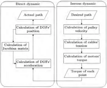
: (7) As shown in Figure 3, calculating the motor torque from the given path is called inverse dynamics and obtaining the actual path from the torque of the motor is called direct dynamics. The related owchart can be seen in Figure 3.
2.3. Control scheme based on sensors' data Robot motion is generally based on point to point and discrete movement. For instance, in tracking a
Figure 3. Dynamic chart.
curved path, the path is divided into set of points and the robot moves from one point to another in a xed step time. The rst step for moving the end-eector of the robot is calculation of the feed forward force that should be exerted on the end-eector. The resultant torque should be implemented by the aid of employed motors. For this purpose, the PWM method is employed in this robot. First, the torque-speed proles of motors are estimated by conducting experimental tests and extracting their related look up table. Then, the required feed forward term of PWM is calculated using feedback linearization and by the aid of the mentioned look up table. However, there are some problems caused by the bad performance of the motors. These problems could be expressed as follows:
For constant input power, motor speed is not con-stant, which is due to the unbalanced motor gears.
The performance of used DC motors is not com-pletely linear and each motor behaves dierently.
So, the feed forward term should be improved using dierent motor controlling strategies. Thus, as shown in Figure 4, two sequential controlling loops are provided by which the angular velocity of the motors is controlled in the inner loop, each 0.01 sec, using feedback terms of PWM, while the end-eector position is controlled in the outer loop, each 0.1 sec, using the feed forward terms of PWM.
The feedback terms of PWM are estimated using six dierent methods, as in Table 1. These methods are modied and are completed step by step in order to reach the most accurate and smooth performance.
In this case, the ON time duration of the motor control pulse is obtained by substituting the theoretical inverse dynamics values of torque and velocity into the characteristic equation of the motor. The characteristic equation of the motor is obtained by conducting some experimental tests on it. The test is done by using dierent ON time durations and hanging dierent masses on the motor. The obtained angular velocity of the motor in each case determines its characteristic equation.
Table 1. Control methods.
PWM = PWMf(computed torque method) 1. Control based on feed forward
term (open loop control)
PWMv= PWMf+ kd(d0 a0) + kp(d a) 2. Speed control of the motors (PD control)
PWMp= PWMf ka(t) kb 3. Pulse control of the motors
PWMt= PWMv ka(t) kb 4. Speed and pulse control of the motors
PWMh= PWMf(feedback linearization control) 5. Position control of the end-eector
PWMs= PWMh+kd(d0 a0)+kp(d a)) ka(t) kb 6. Combination of position control of the
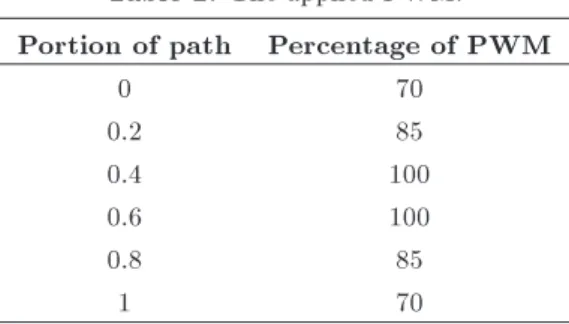
end-eector and speed control of the motors Table 2. The applied PWM.
Portion of path Percentage of PWM
0 70 0.2 85 0.4 100 0.6 100 0.8 85 1 70
In the speed control of the motor, PWMf is
the applied pulse value calculated from the open loop formulas, while the angular velocities of the motors are controlled using a simple PD controller. On the other hand, since the characteristic equation of the motor is exponential (rather than dierential), the PD control coecients, i.e. kd and kp, are optimized
by Ziegler-Nichols methods. 0
d and a0 are desired
and the actual amount of angular speed of the motor and d and a are the same variables for angular
rotation. However, due to nonlinear eects in motor operation, the performance of the robot using a simple PD controller was not reasonable.
The pulse control of the motor (PWMp) is based
on the control of the number of encoder pulses and its comparison with its corresponding desired value. How-ever, robot movement is discrete and non-continuous, which increased the vibration in cables and the whole system. In order to smooth robot movement, in this control method, corrective coecients are applied at each step to provide a Gaussian shape prole of the controlling signal. As shown in Table 2, in each step time, a specic percentage of the PWM, based on the portion of the path that is tracked, is applied to the motor. So, motor angular velocity changes during the step that can smooth robot movement. In this equation, PWMf is the applied pulse calculated
through the related inverse dynamics equation, ka(t) is
a time dependent coecient providing the mentioned Gaussian shape signal, and dened as the ratio of the actual time interval of each step to the desired interval of each step. kb is a gain which species the mean
value of the mentioned Gaussian shape signal, which
is determined based on the feedback received from the previous error signals. By the aid of this approach, the tracking precision is acceptable, although it is not so smooth.
In speed and pulse control, the mentioned pulse speed control signal is smoothed by the aid of previous Gaussian shape corrective gains. In this approach, PWMv is the ON time duration of the motor pulse,
calculated by the speed controller, and ka(t) and kbare
the corrective coecients for providing the Gaussian shape controlling signal. In this case, tracking is smoother and the actual value of the angular velocity of the motor is similar to its desired one.
In position control of the end-eector, the camera and optical sensor data are employed to revise the input parameters and yield the desired value for PWMh. The
accuracy of this method, like other methods, is strongly inuenced by the accuracy of the employed sensors. In this method, the PWM is evaluated using the desired torque and velocity of the motor calculated through the feedback linearization method
Finally, for having complete ecient control, a combination of the position control of the end-eector and the speed control of the motor is used. The initial data for generation of PWM are calculated from the mentioned end-eector position control (PWMh)
and are improved along the path by applying the PD controller to the position and velocity of the motor rotation. Corrective coecients of (ka(t); kb)
are also employed to smooth the response based on the Gaussian shape signal.
Amongst the above mentioned methods, the two combination controllers, i.e. the \speed and pulse control of the motors" and the \combination of position control of the end-eector and speed control of the motor", are able to achieve the desired accuracy in terms of tracking, while the last also produces smoother movement.
3. Hardware setup
A 6-DOF under-constrained cable suspended robot, named ICaSbot (Figure 5), is designed and manufac-tured in Iran University of Science and Technology
Figure 5. (a) Scheme of the designed IUST cable robot [23]. (b) Encoder. (c) Loadcall. (d) Optimal sensor. (e) Camera. Table 3. DC motor's specication.
Motor's
specication Value
Mark Retarding gear motor Model 1.61.070.304 Buhler Reference voltage 12 V
No load speed 150 rpm Stall torque 1.7 N.m No load current 0.3 A Stall current 1.2 A Reduction ratio 1:175
Weight 220 g
(IUST) [22]. In a previous work [22], the robot was controlled in an open loop scheme. Here, a closed loop control scheme is implemented on the robot.
3.1. Motors
Six DC motors are employed as the required actuators, whose specications are listed in Table 3. As shown in Table 3, they are 12 Volt and 1.2 stall current geared motors that run at 150 rpm under free running conditions.
3.2. Sensors
In order to control the robot, there are three dierent kinds of sensor, including encoders for sensing motor rotation, loadcells for evaluating the actual tension of the cables and also a combination of camera and optical sensors to estimate the actual position and orientation of the end-eector.
Encoder. Each motor used in this robot is con-nected to an encoder, which has a high resolution precision, 600 pulses per revolution, and a 3 cm
Table 4. Encoder's specication. Encoder's
specication Value
Mark Autonics
Model E50S8-600-3-T-24
Resolution 600
Output phase A, B, Z
Control output totem pole
Power supply 12-24 V
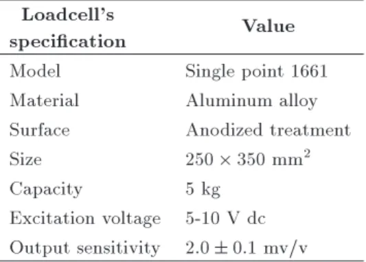
Max allowable revolution 5000 rpm Table 5. Loadcell's specication. Loadcell's
specication Value
Model Single point 1661 Material Aluminum alloy Surface Anodized treatment
Size 250 350 mm2
Capacity 5 kg
Excitation voltage 5-10 V dc Output sensitivity 2:0 0:1 mv/v
diameter circular shaft. The encoder specications are shown in Table 4.
Loadcell. The cables which transfer the load weight are passed over the pulleys of the loadcells and are wrapped around a shaft. The outputs of the loadcells are analog signals in the range of -24 V to 24 V (Table 5).
Combination of camera and optical sensors. The third type of sensor, employed to sense all DOFs of the end-eector, is a combination of camera and
Figure 6. Strategy of recording all of end-eectors DOFs by coupling the camera and laser data [24].
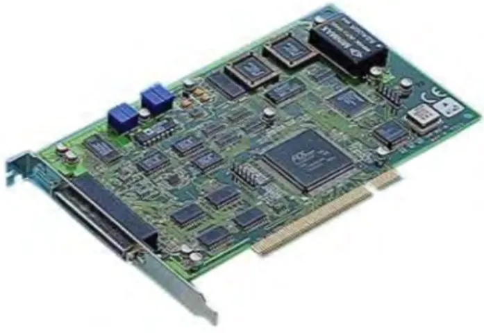
Figure 7. Data card.
laser, which is shown in Figure 6. A new method of recording the position and orientation of the end-eector is proposed based on coupling the data of image processing and laser sensors [23].
3.3. Data card
In order to manage the heavy data of the mentioned sensors, a fast response data transfer protocol is re-quired to handle the complicated nonlinear dynamics equation of a parallel robot, like the cable robot. Thus, two kinds of data card of the Advantech Company (Figure 7) are used to control the robot. Digital ports, analog ports, counter ports and PWM ports are used in this project. Analog data cards are used to manage the loadcell and optical sensor data, while analog cards are employed to drive the motors and sense the encoders.
4. Software setup
A software package is provided for this robot, by which, not only is the operator trained in a virtual
simulator environment, but also the robot can be controlled by the aid of its corresponding Graphical User Interface. The interface is designed in such a way as to support these modules, i.e. taking the input, modeling, simulating, controlling the actuators, recording the sensors and saving the output. The owchart shown in Figure 8 displays the overall scheme of the interface structure.
4.1. Simulator and virtual laboratory
The simulator interface of the ICaSbot is prepared in LabVIEW, which is called RoboCrane, and is designed to be compatible with all versions of Windows. As soon as the mentioned interface is running, the main menu of this program appears in which the following options are available: Direct Kinematics, Inverse Kinematics, Direct Dynamics, Inverse Dynamics and Experiments (Figure 9).
Moreover, two selections of ports and safety keys are also positioned in the main menu. The ports key is prepared, in order to make a connection with the robot using the related interface electrical circuits. In this case, the robot can be easily controlled by the user through the designed graphical interface, while all kinematics and dynamics results are available to be observed and inferred. Finally, the safety rules key includes a series of warnings and primitive data which are necessary for consideration by the user.
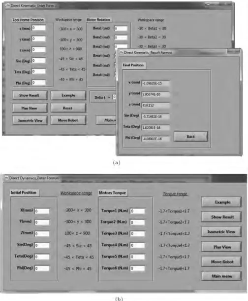
Input. In the direct kinematics window, the user is able to obtain the nal position of the end-eector by specifying the amount of angular rotation of the motors together with the initial position of the end-eector (Figure 10(a)). Also, the direct kinetics window provides a virtual environment in which the user is able to estimate the actual position of the end-eector, as a result of inserting a particular torque value of the motors (Figure 10(b)).
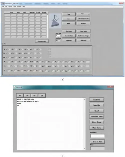
The required torque of each motor for a desired motion of the end-eector can be evaluated in the inverse kinetics of this software by providing the desired path of the end-eector. It is possible to exert the desired path using four dierent methods, including the desired path as a function of time, the point to point look up table, loading previous employed paths and also the G-Code method. As shown in Figure 11(a), the user is able to exert the desired path of the end-eector by providing a table of desired points, by determining the equation of the desired path or by loading the predened path.
The traditional way of implementing the de-sired tracking of the end-eector, G-code, is also considered in the designed GUI, which is positioned in the experiments window (Figure 11(b)). The software is also able to provide the equivalent G-code of every motion of the end-eector, from the input data of the inverse kinetic window.
Figure 8. Flowchart of the structure of the designed GUI.
Outputs. One of the most considerable facilities which is designed in the proposed GUI is the simulator section of the interface in which the user is able to be trained and observe the isometric motion of the robot in a virtual environment based on the input data (Figure 12).
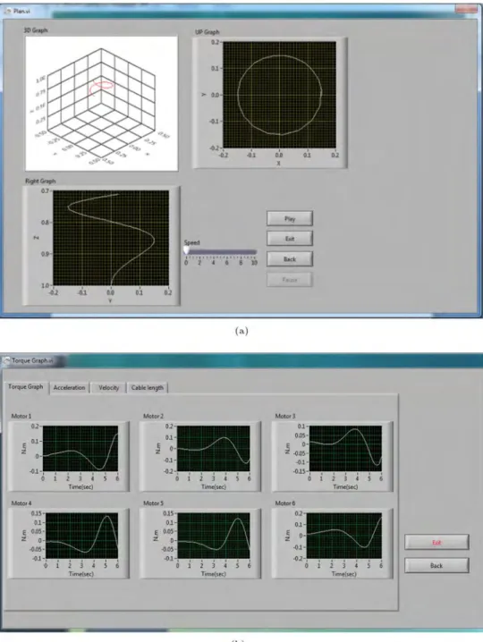
Also, all the DOF proles of end-eector mo-tion can be observed in another environment from dierent points of view in an online manner, for which the rate of simulating steps can be freely determined by the user (Figure 13(a)).
The user is also able to view the resultant proles of the motor torques, DOF velocity and acceleration and even cable elongation as a function of time in this window (Figure 13(b)).
4.2. Hardware control
The control of the real robot is done in the \hardware in the loop result" window. This part is the main control section of the software, which connects the robot to the electrical boards. The controlling commands, i.e. driving the motors and also monitoring the actual data
Figure 9. Main page of RoboCrane.
Figure 11. (a) Inverse dynamic window. (b) G-code section.
Figure 13. (a) Plane view part. (b) Motion graphs.
received from the sensors, can be managed in this part of the GUI. Besides control of the end-eector, the user is able to view and save the data related to the end-eector motion. These data include the angular velocity of the motors recorded by the encoders, cable tension recorded with the aid of loadcells, and the actual position of the end-eector recorded by the position sensors.
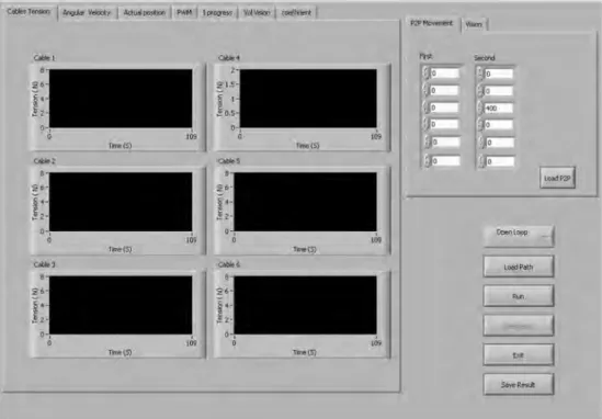
Input. In the main input window of the robot con-trol section, the user commands the robot to move either by loading a predened path, or by inputting the initial and nal points (in point-to-point
move-ment). Also, all of the mentioned controlling meth-ods explained in the previous section can be selected in this window. In addition, the communication pa-rameters for controlling the hardware by computer, image processing specications, and also the calibra-tion coecients of the loadcells and optical sensors are adjustable in this window. As soon as loading the desired path and selecting the control method in the hardware control program, the angular velocity of motors and the required motor torques are cal-culated from the inverse dynamics and kinematics equations and are used as the initial values for ad-justment of the movement parameters (Figure 14).
Figure 14. Main control window.
Figure 15. Loadcells' tab.
Output. After applying the desired inputs to the robot, all the received data from sensors, like the encoder and loadcell, can be observed by opening the tab of the output window. Also, the processing of images during the movement of the robot can be observed and analyzed by referring to another tab. In the loadcell tab (Figure 15), the actual amount of voltage received from the loadcell, which is detected through the analog-to-digital ports, can be observed. In another tab titled `the ON time duration of motor control pulses', the user can observe the ON time duration of pulses associated with all the
motors and can evaluate the performance of the control coecients (Figure 16).
In the next tab, the data related to the actual received pulse of the motors, its desired required pulse and also the dierences between these two values are shown. The bigger dierence means more deviation, with respect to the desired path. Also, in this window, the total quantity of the desired pulses that should be received during tracking, and also, the total quantity of actual pulses received during tracking are illustrated, which indicates the error in the end point (Figure 17).
Figure 16. ON time duration of motor control pulses' tab.
Figure 17. Received pulses' tab.
In the tab related to the end-eector (Fig-ure 18), the user can observe the data of the optical sensors, which are instantaneously extracted by an image processing program on a second computer.
Moreover, the user can save all the resultant data of the path. This data includes the loadcell data, encoder data and the data received from the end-eector position.
5. Experimental tests
The manufactured robot should realize the desired movement with adequate accuracy and smoothness. The accuracy of the robot or actuator depends on some factors, such as the manufacturing precision of mechanical parts, the precision of the electronic system
and the motors used in the robot, the existing clearance in the system, the accuracy of data received from the sensors and the deformation of cables. One of the advantages of the designed GUI is the provision of facilities by this interface to test the accuracy, repeatability, trajectory tracking and also point to point motion. The pose accuracy and pose repeata-bility of the fabricated robot system are measured by referring to ISO9283 standards. The proposed GUI and simulator help to evaluate the performance of the robot from repeatability, accuracy and tracking points of view, based on the mentioned standard.
5.1. Pose accuracy and pose repeatability Pose accuracy and pose repeatability are measured using ISO9283.
Figure 18. The end-eector data's tab.
Accuracy of positioning. For ten cycles in the same direction, with a 1.100 kg payload for the end-eector, this measurement is performed. To meet this goal it is needed to conduct a tracking movement from a denite point towards a desired goal, like zc; yc; xc; n times, and record its actual
des-tination (zj; yj; xj). So, the accuracy of positioning
based on this ISO can be written as: APp=
p
(x xc)2+ (y yc)2+ (z zc)2; (8)
APx=(x xc); APy=(y yc); APz=(z zc);
where:
x = 1 n
n
X
J=1
xj; y = n1 n
X
I=1
yi; z = 1n n
X
J=1
zi: (9)
The mean value of the recorded coordinates related to n times tests are z, y and x. Based on this procedure, the following results are gained. The desired set points are set as Table 6 and the actual end points of the tracked end-eector for each test can be seen as Table 7.
Using the mentioned equations, we have the following results for the accuracy performance of the system, which is an acceptable result (Table 8):
APp=
p
(105:6 100)2+(91:9 100)2+(803 900)2
) APp= 11:31: (10)
Table 6. The set point of ISO tests. xc yc zc
100 100 800
Table 7. Resulted points of ISO tests. No. xj yj zj
1 103.8 93.5 763.5 2 102.3 96.7 675 3 104.2 100.9 751.6 4 106.9 100.8 832.7 5 108.9 100.1 832.7 6 111.3 96.9 800.4 7 105.4 81.8 789.6 8 104.1 79.2 862.0 9 105.8 82.7 832.2 10 103.1 86.3 891 Table 8. Actual mean value.
x y z
105.6 91.9 803
Repeatability of positioning. Repeatability is the conventional accuracy of the end point posi-tioning of the end-eector for n times tests and the compatibility of the position and orientation of these results. Based on this standard convention positioning, repeatability (RPL) is the radius of the sphere like:
RPL= L + 3SL; (11)
L= 1nXn
j=1
Lj; Li=
q
(xj x)2+(yi y)2+(zj z)2;
SL=
v u u u t
n
P
j=1(Lj L) 2
n 1 :
have the following results for the repeatability of the robot, which, again, proves the good performance of the robot:
RPL= L + 3SL; L = 48:6; SL= 36;
) RPL= 156:8: (12)
5.2. Triangle trajectory tracking test
For verifying the precision of the robot in tracking a predened trajectory, a triangle test is conducted, in which, the end-eector is responsible for tracking a right-angled triangle trajectory. Eq. (13) shows the triangle path:
8 > < > :
x = 0
y = 0:1 (0:1 2:5) t
z = 0:9
0 < t 2:5
8 > > < > > :
x =
0:1 2:5
(t 2:5) y = 0
z = 0:9
2:5 < t 5
8 > > > > < > > > > :
x = 0:1
0:1 2:5
(t 5) y =
0:1 2:5
(t 5) z = 0:9
5 < t 7:5 (13)
The result of trajectory tracking in the virtual simula-tor and also the camera data are shown in Figure 19. It can be seen from Figure 20, that acceptable compat-ibility can be observed between the simulation results and experimental tests.
A comparison of the angular velocity of the mo-tors between the simulation and experimental results is
Figure 19. (a) Isometric view and plan view of triangle tracking in GUI simulator. (b) Camera data in tracking.
Figure 21. Motors' speed results.
shown in Figure 21. A little deviation and the vibration of the experimental results around the simulation pro-les can be referred to as the un-modeled uncertainties of the robot, such as the structural exibility and friction of the manufactured robot, which are not modeled in the simulation.
A comparison of the actual loadcell data with the tension of the cables obtained by MATLAB simulation is plotted in Figure 22. The simulation result of cable tension is the smoother graph shown in red, and the experimental graph that oscillates around its mean value is shown in blue.
It is observed that there is a dierence between the value of cable tension at the initial moments of movement between the experiment and the simulation of a full load test, which is the result of the initial shock and vibration of the robot at the starting moment, while overcoming the static friction of the structure. However, this deviation is compensated for by the aid of the employed controller.
To sum up, it can be stated that comparing exper-imental tests with simulation results is possible thanks to the mentioned designed simulator and GUI. It can be concluded that not only does an acceptable compat-ibility exist between the simulation and experiments, which proves the correctness of the procedure and the eciency of the controlling algorithms provided by the designed GUI, but also, that there is some vibrating behavior of the experimental signals around the mean
value of the simulation results due to the clearance of the motor and joints, the structural exibility of the robot, cable vibrations and etc.
6. Conclusion
Designing and programming a graphical interface was undertaken for the manufactured cable robot of IUST involving a graphical user interface, in order to have a faster and better connection to the cable robot, and also a virtual simulator environment for training and educational purposes in robotics laboratories and industrial environments. The designed GUI consists of the inverse and direct kinematics and dynamics of the robot and provides the possibility of importing the required path and commands and exporting the full kinematic and kinetic results of the robot. Also, the mentioned interface can display the simulated motion of the end-eector in a virtual three dimensional environment at the same time as depicting its resultant kinematics and kinetics proles.
Moreover, the users are also able to control the hardware of the robot easily by the aid of the same software in the part of the \hardware in the loop result" window of the software. Though the pre-sented interface is especially characterized for the cable robot of IUST and all of its kinematics and kinetics formulations, and also its graphical interface, which is compatible with the mentioned RoboCrane, this
Figure 22. Lodcell results.
software package would be simple to use for analyzing the motion of all sorts of robots, for educational and industrial purposes, with a little correction in the software.
It is seen that it is possible to import the re-quired path by the aid of three dierent protocols consisting of a predened trajectory as a function of time, point to point regulation and G-code. The capability of G-code interpretation implemented in this interface has provided an excellent environment for training the users for programming and controlling robot motion. It is shown that all sorts of required sequential controlling methods for simultaneous control of the motors and end-eector is possible by the aid of the designed GUI in which all controlling gains and dynamic specications are adjustable. Finally, it was stated that the possibility of evaluating the performance of the robot based on conventional ISO standards of accuracy and repeatability is provided by the aid of the proposed designed GUI. Moreover, the eciency of the system and the designed GUI was proved by the aid of some experimental tests of predened tracking conducted on the ICaSbot, and by comparing its kinematic and kinetic results with the output of MATLAB simulations. The acceptable compatibility of the results showed the eciency and
correctness of the designed simulator. However, a little deviation and vibration were also observed, which is related to structural un-certainties and can be easily detected and improved with the aid of the proposed GUI.
References
1. Bonev, I., The True Origins of Parallel Robots, Par-alleMIC (2003).
2. Rodney, R., Graham, T. and Lippitt, T. \On the inverse kinematics, statics, and fault tolerance of cable-suspended robots", Journal of Robotic Systems, 15(10), pp. 581-597 (1998).
3. Albus, J., Bostelman, R. and Dagalakis, N. \The NIST robocrane", Journal of Robotic Systems, 10(5), pp. 709-724 (1993).
4. Shiang, W., Cannon, D. and Gorman, J. \Dynamic analysis of the cable array robotic crane", In Robotics and Automation, 1999, Proceedings, 1999 IEEE Inter-national Conference on, 4, pp. 2495-2500 (1999). 5. Chang, A.H. \Experimental development of the mobile
vestibular platform", SUNFEST, p. 24 (2004). 6. Oh, S. and Agrawal, S.K. \A reference governor-based
IEEE Transactions on Control Systems Technology, 13(4), pp. 639-645 (2005).
7. Marcu, C., Lazea, Gh., Herle, S., Robotin, R. and Tamas, L. \3d graphical simulation of an articulated serial manipulator based on kinematic models", In Robotics in Alpe-Adria-Danube region (RAAD), 2010 IEEE 19th International Workshop on, pp. 143-148, IEEE (2010).
8. Samaka, M. \Robot task-level programming language and simulation", In Proc. of World Academy of Science, Engineering and Technology, 9, pp. 99-103 (2005).
9. Delsignore, M.J. and Krovi, V.N. \Screw-theoretic analysis models for felid jaw mechanisms", Mechanism and Machine Theory, 43(2), pp. 147-159 (2008). 10. Veljko, P., Vukobratovic, M., Jovanovic, K. and
Medenica, M. \Virtual Mechatronic/Robotic labora-tory - A step further in distance learning", Computers & Education, 55(2), pp. 465-475 (2010).
11. Korayem, M.H. and Omoumi, A.K. \A novel exper-imental setup for Atlas II robot using visual basic", In Mechatronics and Machine Vision in Practice, Pro-ceeding, Fourth Annual Conference on, IEEE, pp. 8-13 (1997).
12. Seungjun, K., Mahalik, N.P., Dey, A.K., Ryu, J. and Ahn, B. \Feasibility and infrastructural study of AR interfacing and intuitive simulation on 3D nonlinear systems", Computer Standards & Interfaces, 30(1), pp. 36-51 (2008).
13. Shin'ichiro, N. \Choreonoid: Extensible virtual robot environment built on an integrated GUI framework", In System Integration (SII), 2012 IEEE/SICE Inter-national Symposium on, IEEE, pp. 79-85 (2012). 14. Carlos, J., Francisco, A., Candelas, A., Puente, S.T.
and Torres, F. \Hands-on experiences of undergradu-ate students in automatics and robotics using a vir-tual and remote laboratory", Computers & Education, 57(4), pp. 2451-2461 (2011).
15. Mayhew, D., Bachrach, B., Rymer, W.Z. and Beer, R.F. \Development of the MACARM-a novel cable robot for upper limb neurorehabilitation", In Rehabili-tation Robotics, 2005. ICORR 2005, 9th International Conference on, IEEE, pp. 299-302 (2005).
16. Purang, A., Salcudean, S.E., Zhu, W.H., DiMaio, S.P. and Sirouspour, M,R. \A user interface for robot-assisted diagnostic ultrasound", In Robotics and Au-tomation, 2001. Proceedings 2001 ICRA, IEEE In-ternational Conference on, 2, IEEE, pp. 1549-1554 (2001).
17. Joshua, V., Smith, A., Kang, S.J. and Singhose, W. \Predictive graphical user interface elements to improve crane operator performance", Systems, Man and Cybernetics, Part A: Systems and Humans, IEEE Transactions on, 41(2), pp. 323-330 (2011).
18. Hassan, B.N.M.K., S.S.M., Mohideen, S.S.K., Ba-haruddin, M.Z., and Anuar.A. \RS-485 interface for boiler header inspection robot prototype", Procedia Engineering, 41, pp. 1490-1496 (2012).
19. Nicola, G., Silvestri, G., Antonello, S., Menegatti, E. and Pagello. E. \A 3d model of humanoid for usarsim simulator", In First Workshop on Humanoid Soccer Robots, pp. 17-24 (2006).
20. Miyuranga, K.M. and Annaz. F.Y. \GUI teaching pendant development for a 6 axis articulated robot", In Trends in Intelligent Robotics, Automation, and Man-ufacturing, pp. 111-118, Springer Berlin Heidelberg (2012).
21. Alp, Abdullah, B. and Agrawal, S.K. \Cable sus-pended robots: design, planning and control", In Robotics and Automation, Proceedings, ICRA'02. IEEE International Conference on, 4, IEEE, pp. 4275-4280 (2002).
22. Korayem, M., Bamdad, H.M., Tourajizadeh, H., Shaee, H., Zehtab, R.M. and Iranpour, A. \Develop-ment of ICASBOT: A cable-suspended robot's with zix DOF", Arabian Journal for Science and Engineering, pp. 1-19 (2013).
23. Korayem, M., Khayatzadeh, H.S., Tourajizadeh, H. and Taherifar, M. \Online recording the position and orientation of an end-eector of a spatial cable-suspended robot for close loop control using hybrid sensors", Journal of Control Engineering and Technol-ogy, 3(1) (2013).
Biographies
Moharam Habibnejad Korayem was born in Tehran, Iran, in 1961. He received his BS (Hon) and MS degrees in Mechanical Engineering from Amirkabir University of Technology, Tehran, Iran, in 1985 and 1987, respectively, and a PhD degree in the same subject from the University of Wollongong, Australia, in 1994. He is currently Professor in Mechanical Engineering at the Iran University of Science and Technology, where he has been involved in teaching and research activities for the last 17 years in the eld of robotics. His research interests include dynamics of elastic mechanical manipulators, trajectory optimiza-tion, symbolic modeling, robotic multimedia software, mobile robots, industrial robotics standards, robot vision, soccer robots, and the analysis of mechanical manipulators with maximum load carrying capacity. He has published and presented more than 450 papers in international journals and at conferences in these areas.
Seyed Mohammad Maddah was born in Kord-kuy, Iran, in 1987. He received his BS degree in Manufacturing Engineering from Tabriz University, in 2009 and his MS degree from Iran University of Science and Technology in Mechatronics, in 2011. He is now a PhD degree candidate in Manufacturing Engineering at Babol University, Iran, and has been involved in teaching and research activities for one year at dierent universities. His research interests
include robotic systems, manufacturing processes, and automation.
Mohammad Taherifar was born in Stockholm, Swe-den, in 1988. He received his BS degree in Mechanical Engineering from Iran University of Science and Tech-nology, Iran, in 2010, and his MS degree from Iran University of Science and Technology (IUST), Iran, in 2012, in the eld of Dynamics, Control and Vibration. He has been involved in work-group research activities for more than one year in the eld of robotics at the robotics lab of IUST. His research interests include robotic systems, automotive engineering, controlling systems, vision control, and dynamics and control of nonlinear systems.
Hami Tourajizadeh was born in Tehran, Iran, in 1984. He received his BS degree in Mechanical En-gineering from KNT University of Technology, Iran, in 2006, and his MS degree from Iran University of Science and Technology, Iran, in 2008 in the eld of Applied Mechanical Design. He is currently a PhD degree candidate at IUST in the eld of control and vibration. He has published and presented several papers in journals and at conferences, including one book chapter. He has been involved in teaching and research activities for more than four years in the eld of control and dynamics at dierent universities. His research interests include robotic systems, automotive engineering, control and optimization, parallel manipu-lators, industrial automation and mechatronic systems.
![Figure 1. A sketch of the cable system along with geometric parameters [21].](https://thumb-us.123doks.com/thumbv2/123dok_us/8391524.2229614/3.892.114.410.147.461/figure-sketch-cable-geometric-parameters.webp)