TECHNICAL UNIVERSITY OF CLUJ-NAPOCA
ACTA TECHNICA NAPOCENSIS
Series: Applied Mathematics, Mechanics, and Engineering Vol. 60, Issue III, September, 2017
THE INFLUENCE OF ACCURACY IN ESTABLISHING THE ORIGIN OF
THE PART ON THE MACHINING ACCURACY
Nicolae PANC, Claudiu SCHONSTEIN, Ioan Gheorghe VUSCAN
Abstract: While machining parts, the errors occurs due to factors with a systematic or a random character. Among these factors, the errors due to clamping devices have a systematic character and are qualitatively significant. There are some parts which, in order to be processed, need to be inclined after one or two angles. These parts need devices that allows the rotation based on certain angles. Establishing the origin of the part for machining, on numerically controlled machines is difficult if are not used machines in 4 or 5 axis. This article presents the causes of the errors which occurs when the origin of the part is established incorrectly and the way in which is correctly established the part origin..
Key words: CNC machines, clamping devices, fixing error, zero point.
1. INTRODUCTION
The manufacturing of parts on numerically controlled machines is currently predominant in industry. In order to process a part, is used a technological system, which has in its componence the machine, a tool, a device, and a piece. Each of these elements, are introducing errors which influence the quality of the manufactured part, as it results in the studies presented in [1] [2] [3].
In the case of CNC machines, the origin of the part is determined after the part is fixed to the clamping device of the machine`s table. The origin of the part represents a coordinate system associated with the part, which is referenced for all movements performed during machining. This Op point can be chosen arbitrarily, anywhere on the part. It is usually chosen at the one end of the piece, at the center of the piece, whether it is symmetrical or a point that makes part programming easier [4]. For the revolution parts, the origin of the part is at the intersection between the axis of rotation and a certain front surface, perpendicular to the axis of rotation of the part (see Figure 1 a)).
When processing prismatic parts on milling machines and CNC machining centers, the
origin of the part is chosen in one of its corners or in a reaming (Figure 1 b)). For parts requiring multiple clamps, there are several origins of the part that are different for each clamp. There are several ways to take the zero point on the surface of the part. It is usually taken with the tool, the control pin, the touch probe, the mechanical or electronic 3D tester [4]. Each way has its advantages and disadvantages.
a) b)
Fig. 1. Zero point, a)for turning, b)for milling There are often parts where certain processed surfaces are inclined towards the reference surfaces of the part. Two examples of such parts are presented in Figure 2, where the reaming hole axis or certain surfaces are inclined at an one or two angles, towards the reference plan.
a) b)
In order to clamp these parts for machining, clamping devices are required to allow changing its position by turning and tilting. The most common devices of this kind are: the tilting table, the tipping table, the rotating table, the indexing devices (rotating table, the dividing head), the 4th and 5th 4th axis rotary table. The most efficient machining method for these types of parts is the use of machines that allow the processing in 5th axis rotary table.
The advantage of using the 4th axis rotary table is that the exact position of the axis of rotation is known or can be easily determined, and the software of the CNC machine automatically calculates the position of the origin of the part after its tilting. Due to cost reasons, these types of CNC machines are not always available, so the usual clamping devices (tilting table, tipping table, etc.) are used.
The problem which is occurring, while processing parts with inclined surfaces after one and especially two angles, is that the zero point cannot be taken in the machining position. Therefore, for good machining precision, it is recommended to take the zero point in the parallel position of the part with the reference plan. Subsequently, the part is shifted to the working position and the new position of the origin, that moved from the original position Opin to the Opfin position, is analytically
established and entered into the CNC machine tool settings.
The origin of the part is established in two ways: • directly on the inclined part at the required
angles, the way being less accurate and not recommended.
• by analytical calculation, knowing the initial position of the origin of the part, the rotation angle and the distance between the original origin and the rotation axis.
This paper aims to illustrate how the incorrect setting of origin influences the machining accuracy of the part. Also, it presents the analytical way in which the calculation of the movement of the origin Opin in Opfin position is
done.
2. ANALYTICAL MODEL FOR
TRANSFORMATION OP ORIGIN IN E3
For the analytical determination of the movement of point 0 in space, from the initial positionOpinxinyinzin, in which point 0 was taken,
at the final position of Opfinxfinyfinzfin, in which
the point was moved for processing, the Cartesian space E3 is used. In the E3 space, the
Op position is invariably linked to an Oxyz
reference system. The calculation of the movement of the Op point in the E3 space is done
easily, using the 4x4 transformation matrix [5]. The Op point is described in the Cartesian space
using homogeneous coordinates by a column vector shown in expression (1)
1
p
x y O
z
=
(1)
The final position and orientation of the Op point
with respect to the Oxyz reference system is the result of a composed movement, consisting in translation and rotation [6]. For the translation of the Op point from the initial position (Opin) into
the final position (Opfin), the equation (2) is used
as.
In (1) it have been marked xfin, yfin, zfinthe final position of the point in the E3 space tx, ty,
z
t the distance between the fixed reference point and the point Op to be translated.
1 0 0 0 1 0 0 0 1 0 0 0 1
1 1
fin in
x
fin in
y fin
p fin in
z
x t x
t
y y
TranO
t
z z
= = ⋅
(2)
For the rotation of the Op point from the initial to the final position, the equations (3) are used, in the most general case, when there are rotations after all three axes [7].
In (3) the parameters are:Rot O xp( , )
α
therotation of the part around x axis with angleα , ( , )
p
Rot O y
β
the rotation of the part around yaxis with angleβ, and Rot O zp( , )
γ
the rotation1 0 0 0 0 cos sin 0
( , ) ,
0 sin cos 0
0 0 0 1
cos 0 sin 0
0 1 0 0
( , ) ,
sin 0 cos 0
0 0 0 1
cos sin 0 0 sin cos 0 0 ( , )
0 0 1 0
0 0 0 1
p
p
p
Rot O x
Rot O y
Rot O z
α α α α α β β β β β γ γ γ γ γ − = = − − = (3)
In Figure 3, is schematically shown how a part with a particular shape, that is contained in a parallelepiped, can move in the Euclidian space, by rotating around one or two angles, depending on the kinematics needed for the part to be processed.
Fig. 3. The movement of part origin in E3
For the calculation of the movement of the point into space, there is used the equation, given in (4) as:
(( , , ), ( , , )) (( , , ), ( , , ))
fin fin f
p p p
s p
O TransO Rot O x y z
Rot O x y z
α β γ
α β γ
= ⋅ ⋅
⋅ (4)
In (4), the parameters are: Opfinthe final position
of the point, TransOpfin the matrix of translation
of the point in E3, Rot Opf(( , , ), ( , , ))x y z
α β γ
therotation matrix of the first tilting angle of the part, established from equation (3) based on the rotation axis, Rot Ops(( , , ), ( , , ))x y z
α β γ
therotation matrix of the second tilting angle of the part, established from equation (3), based on the rotation axis.
If the part tilts only at an angle, then equation (4) is reduced to equation (5).
(( , , ), ( , , ))
fin fin f
p p p
O =TransO ⋅Rot O x y z α β γ (5)
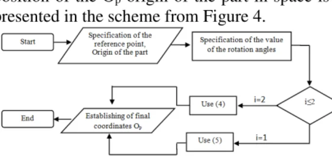
The analytical calculation method of the final position of the Op origin of the part in space is
presented in the scheme from Figure 4.
Fig 4. Schematic representation of the procedure for calculating the trajectory of origin Op
Following the steps of the logical scheme shown in Figure 4, it is possible to analytically, in a simple and fast way, the coordinates of the origin of a part, moving in space due to its rotation, with one or two angles. The calculation method has not been extended to the possibility to tilt the part at three angles, because the probability of processing such a part on common machines in 2.5, 3 or 4 axes is extremely low.
3. EXPERIMENTAL SETUP
The purpose of this paper is to show how the processing accuracy is influenced by how the origin of the part is determined. A 3D WERC30FG40 3D tester, with a 0.001 [mm] accuracy, was used in order to determine the origin of the part. The research have been performed on the 3-axis machining center DMG 333 and on the CNC machining center, in 4th axis rotary table, FGT 2345. Two tilted tables, GFH 300x400 [mm], with an inclination between 0-900 and with a positioning accuracy of 0.02 [mm], have been used.
Table 1 Number
of tilting angles
Device
Mood of establishing for the origin Empirical Analytical
One angle
Tilting
table Yes Yes
4th axis rotary
table
No Yes
Two angles
Two tilting tables
Yes Yes
4th axis rotary table and
tilting table
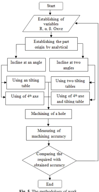
Fig. 5. The methodology of work
One 300 [mm] length part, 5 holes have been performed, at a distance of 200 [mm] from the origin. The inclination of the part was made after the first angle α=300 and after the second angle β =150.
The methodology for carrying out the experiments is shown in Figure 5.
4. REZULTS
The processing of the data has been done after processing the parts. Table 2 presents the average data obtained from the processing of measured data.
The measurement accuracy was influenced by the precision of the measuring instrument, considered at 0.005 [mm] for distances between 200-400 [mm].
Table 2
Number of tilting angles
Device
Mood of establishing for the origin
Empirical Analytical
One angle
Tilting table
0.1 0.04
4th axis rotary
table
0 0.01
Two angles
Two tilting tables
0.15 0.06
4th axis rotary table and
tilting table
0 0.03
From the data presented in Table 2, it can be observed that the analytical method of determining the origin of the part is superior to the empirical method. The way in which the empirical determination of origin influences the precision of machining is presented in the following paragraph.
5. DISCUSSION
The precision of determining the origin of the part for processing, directly influences the machining precision. If the origin is determined analytically, as shown in Figure 4, then the precision of origin is influenced only by the precision of the device used, in this case the tilted table and the 4th axis.
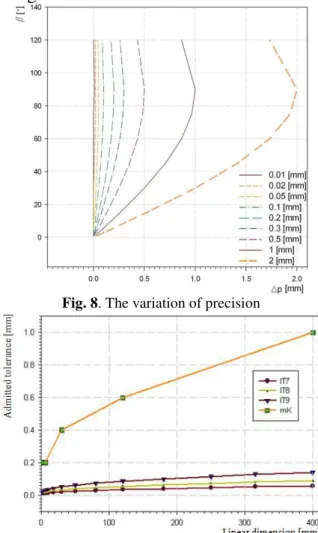
If the origin is determined empirically, through direct touching of the intersection point between the three reference planes that determine the Op position on the piece, as shown in Figure 6, then a palpation error results, as shown in Figure 7. Figure 8 shows how the rotation angle of the part influences the position precision of the part`s origin. This influence is manifested by the movement of the theoretical zero point Ot of the
part, that the operator wishes to set at a practical point Op. This movement, although varying from
tolerance field of the linear dimensions according to DIN ISO 2768- mk, for the middle precision class, and SR EN 20286-2: 1997 for nominal sizes to be machined in the IT9, IT8 and IT7 precision class. The choice of the dimension range between 0-400 [mm] and the IT7, IT8, IT9 precision classes, and also the free mK allowances, have been made because this range and precision classes are common for parts that are machined by cutting.
Fig. 6. Part inclined by an angle
Fig. 7. The way the palpation error results For the processing of parts that requiring tilting the part after one or two angles, the processing precision required on the drawing must be taken into account. As shown in Figure 9 and Figure10, the precision of establishing the zero point decisively influences the precision of processing.
For example, if is taken a part with a maximum dimension of 200 [mm], showing tolerated functional quotas in the IT7, IT8 precision class and the free allowances are in mK in accordance with DIN ISO 2768, the following data will be obtained, as presented synthetic in Table 4. Table 3 shows that, for a value of 0.05 [mm] of the ∆p value of the palpation error that we take on a part inclined at a angleβ =30°, it result that the quotas in the IT7 precision class will be rebated only due to the precision of establishing the zero point.
In order to avoid this phenomenon, it is recommended to use the method of taking the zero point in the position of fixation with a angle β=0 °, after which the part is inclined at the desired angles and the origin is calculated analytically by the method described in paragraph 2 of the paper, and it is entered in the settings of the machine.
Fig. 8. The variation of precision
Fig. 9. The value of the tolerance field for linear usual dimensions
Table 3
β [deg.] Palpation variation ∆p [mm] IT7 IT8 mK 0.01 0.02 0.05 0.1 0.2
5 0 0 0 0 0.017
0
.0
2
1
0
.0
3
3
±
0
.5
15 0 0 0.013 0.026 0.052 30 0 0.01 0.025 0.05 0.1 45 0 0.014 0.035 0.071 0.141 90 0.01 0.02 0.05 0.1 0.2
origin, this calculation being made by the machine’s software.
6. CONCLUSION
This paper aims to show how machining precision is influenced by determining the origin of the part, in the case of parts being processed after it had been initially inclined by one or two rotation angles. Although machine tool manufacturers have solved the way for determining the origin of the part in usual cases, for such parts, we have the inconvenience that it is necessary to use CNC machines, with a minimum of 4th axis rotary table. In the absence of such equipment, the results presented in this paper are useful for obtaining high precision. These results can also be used in other engineering situations where is asked rapid and accurate calculation of the way a body moves into space.
ACKNOWLWDGEMENTS
The authors would like to express their gratitude to Nagy Zoltan Eng. of S.C. Matex S.R.L. Cluj-Napoca and Beldean Calin Ph.D. Eng of S.C. Rominserv S.A. Zalau. for supporting this work
8. REFERENCES
[1] Panc N., Bocăneţ V., Bulgaru M., Beldean C.,
Research on holes finishing operations performance by cutting, Acta Technica Napocensis, Series: Applied Mathematics and Mechanics, Vol 57, Issue 1 , pp. 47-50, 2014; [2] Panc N., Vuscan I., Balc N., Research on the
deformations caused by the manufacturing devices onto the parts with low rigidity, Academic Journal of Manufacturing Engineering 11(4), pp. 10-13, 2013
[3] Ratchev S., Liu S., Huang W., Becker A.A.,
Milling error prediction and compensation in machining of low-rigidity parts, International Journal of Machine Tools & Manufacture 44 (2004) 1629–1641
[4] Vuscan I.Gh., Panc N., Bazele prelucrarii mecanice, Editura Scoala Ardeleana, Cluj-Napoca, 2015;
[5] Negrean I., Vuscan I., Haiduc N., Robotics : kinematic and dynamic modelling, Editura Didactica si Pedagogica, Bucuresti, 1998; [6] Lorenzo Sciavicco, Bruno Siciliano, Modelling
and control of robot manipulators, Springer– Verlag London Limited, 2004;
INFLUENTA PRECIZIEI DE STABILIRE A ORIGINI PIESEI ASUPRA PRECIZIEI DE PRELUCRARE
Rezumat: La prelucrarea pieselor apar erori datorate unor factori ce au character systematic sau aleator. Dintre acesti factori erorile datorate dispozitivelor de fixare au un character systematic si sunt de inseminate calitativ. Exista anumite piese care pentru a fi prelucrate este necesar sa fie inclinate dupa unul sau doua unghiuri. Aceste piese necesita dispositive ce permit rotatia lor dupa anumite unghiuri. Stabilirea origini piesei in vederea prelucrarii pe masini cu comanda numerica in aceste situatii este dificila daca nu se utilizeaza masini cu 4 sau 5 axe. Acest articol prezinta cauzele erorilor care apar cand originea piesei este stabilita gresit si modul in care se stabileste corect originea piesei.
Nicolae PANC, Lecturer, Ph.D, Eng, Technical University of Cluj-Napoca, Department of Manufacturing Engineering, E-mail: [email protected], 103-105 No., Muncii Blvd., Office G19B, 400641, Cluj-Napoca.
Claudiu SCHONSTEIN, Lecturer, Ph.D, Eng, Technical University of Cluj-Napoca, Department of Mechanical Systems Engineering, E-mail: [email protected], 103-105 No., Muncii Blvd., Office C103A, 400641, Cluj-Napoca.