for VMware
®
View
™
B E S T P R A C T I C E STable of Contents
Introduction . . . . 3
Windows Disk I/O Workloads . . . . 3
Base Image Considerations . . . . 4
Storage Protocol Choices . . . . 6
Storage Technology Options . . . . 9
Storage Array Decisions . . . . 15
Increasing Storage Performance . . . . 16
Conclusion . . . . 18
About the Author . . . . 19
Introduction
VMware® View™ is an enterprise-class virtual desktop manager that securely connects authorized users to centralized virtual desktops. It allows you to consolidate virtual desktops on datacenter servers and manage operating systems, applications and data independently for greater business agility while providing a flexible high-performance desktop experience for end users, over any network.
Storage is the foundation of any VMware View implementation. This document is intended for architects and systems administrators who are considering an implementation of View. It outlines the steps you should take to characterize your environment, from determining the type of users in your environment to choosing storage protocols and storage technology.
The paper covers the following topics: • Windows Disk I/O Workloads • Base Image Considerations • Storage Protocol Choices • Storage Technology Options • Storage Array Decisions • Increasing Storage Performance
Windows Disk I/O Workloads
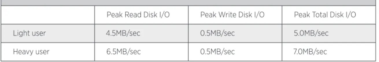
To make appropriate storage sizing and design decisions, you need to understand the disk input and output (I/O) characteristics of Windows XP and Windows 7. For characterization purposes, you can characterize workers as light or heavy users. Light users typically use email (Outlook), Excel, Word, and a Web browser (Internet Explorer or Firefox) during the normal workday. These workers are usually data entry or clerical staff. Heavy users are full knowledge workers using all the tools of the light worker (Outlook, Excel, Word, Internet Explorer, and Firefox) and also working with large PowerPoint presentations and performing other large file manipulations. These workers include business managers, executives, and members of the marketing staff. Information Worker Disk I/O Throughput, adapted from the paper “VMware VDI Server Sizing and Scaling” (see Resources for a link), compares the disk usage of light and heavy users for a large number of VMware View (previously known as VDI) desktops—approximately 20 on a single VMware ESX host. It suggests that over 90 percent of the average information worker’s disk I/O consists of read operations.
INFORMATION WORKER DISK I/O THROUGHPUT
Peak Read Disk I/O Peak Write Disk I/O Peak Total Disk I/O
Light user 4.5MB/sec 0.5MB/sec 5.0MB/sec
Heavy user 6.5MB/sec 0.5MB/sec 7.0MB/sec
To make intelligent storage subsystems choices, you need to convert these throughput values to I/O operations per second (IOPS) values used by the SAN and NAS storage industry. You can convert a throughput rate to IOPS using the following formula:
Throughput (MB/sec) x 1024 (KB/MB)
=
______________________________ Block size (KB/IO)
Although the standard NTFS file system allocation size is 4KB, Windows uses a 64KB block size and Windows 7 uses a 1MB block size for disk I/O.
Using the worst case (heavy user) scenario of 7.0MB/sec throughput and the smaller block size of 64KB, a full group of approximately 20 Windows virtual machines generates 112 IOPS.
Base Image Considerations
Most View implementations deploy hosted desktops from a small number of base, or golden master, images. Because these base images are meant to be reused, you should take special care when creating them. You can optimize the image size by adjusting operating system settings, application sets, and user data. Optimizing operating system settings has the additional benefit of improving overall system performance.
Operating Systems Settings
Reducing the operating system’s footprint, regardless of the underlying storage technology, is a View
architecture best practice. After it is virtualized, the operating system no longer needs many of the components found in a traditional desktop PC implementation. You can use various available utilities to streamline the base operating system by removing unnecessary features.
Although the primary goal is to reduce the image size, increased performance is an important side effect. Removing unnecessary components reduces the overhead associated with unneeded processes and services within a virtual desktop.
Application Sets
In a View deployment, the manner in which applications are deployed directly affects the size of the final desktop image. In a traditional desktop environment, applications can be installed directly on the local hard disk, streamed to the desktop, or deployed centrally using a server-based computing model.
In a View environment, the basic deployment methodologies remain unchanged, but View opens up new opportunities for application management. For instance, multiple View users can leverage a single generic desktop image, which includes the base operating system as well as the necessary applications. Administrators create pools of desktops based on this single golden master image. When a user logs in, View assigns a new desktop based on the base image—with hot fixes, application updates, and additions—from the pool.
Managing a single base template rather than multiple individual desktop images, each with its own application set, reduces the overall complexity of application deployment. You can configure View to clone this base template in various ways—for example, at the level of the virtual disk, the datastore, or the volume—to provide desktops with varying storage requirements for different types of users.
If you use storage-based or virtualization-based snapshot technologies, adding locally installed applications across a large number of virtual machines can result in higher storage requirements and decreased
performance. For this reason, VMware recommends that you deploy applications directly to the virtual machine only for individual desktops based on a customized image.
Although traditional server-based computing models have met with limited success as a means to deploy centralized applications, you can use this approach to reduce the overhead associated with providing applications to virtualized desktops.
Server-based computing can also increase the number of virtual desktop workloads for each ESX host running View desktops, because the application processing overhead is offloaded to the server hosting the applications. Server-based computing also allows for flexible load management and easier updating of complex front-line business applications as well as global application access. Regardless of the design of your View deployment, you can use server-based computing as your overall method for distributing applications.
User Data
A best practice for user-specific data in a View desktop is to redirect as much user data as possible to network-based file shares. To gain the maximum benefit of shared storage technologies, think of the individual virtual desktop as disposable. Although you can set up persistent (one-to-one, typically dedicated) virtual desktops, some of the key benefits of View come from the ability to update the base image easily and allow the View infrastructure to distribute the changes as an entirely new virtual desktop. You perform updates to a View desktop by updating the golden master image, and View provisions new desktops as needed.
If you are using persistent desktops and pools, you can store user data locally. However, VMware recommends that you direct data to centralized file storage. If you separate the desktop image from the data, you can update the desktop image more easily.
In a Windows infrastructure, administrators have often encountered issues with roaming profiles. With proper design, however, roaming profiles can be stable and you can successfully leverage them in a View environment. The key to successful use of roaming profiles is to keep the profile as small as possible. By using folder
redirection, and especially by going beyond the defaults found in standard group policy objects, you can strip roaming profiles down to the bare minimum.
Key folders you can redirect to reduce profile size include: • Application Data
• My Documents • My Pictures • My Music • Desktop • Favorites • Cookies • Templates
Regardless of whether you are using persistent or nonpersistent pools, local data should not exist in the desktop image. If your organization requires local data storage, it should be limited.
It is also important to lock down the desktop, including preventing users from creating folders on the virtual machine’s root drive. You can leverage many of the policy settings and guidelines that exist for traditional server-based computing when you design security for your View deployment.
A final benefit of redirecting all data is that you then need to archive or back up only the user data and base template. You do not need to back up each individual user’s View desktop.
Configuration Concerns
When building a desktop image, make sure the virtual machine does not consume unnecessary computing resources. You can safely make the following configuration changes to increase performance and scalability: • Turn off graphical screen savers. Use only a basic blank Windows login screen saver.
• Disable offline files and folders.
• Disable all GUI enhancements, such as themes, except for font smoothing. • Disable any COM ports.
• Delete the locally cached roaming profile when the user logs out.
It is important to consider how the applications running in the hosted desktop are accessing storage in your View implementation. For example, if multiple virtual machines are sharing a base image and they all run virus scans at the same time, performance can degrade dramatically because the virtual machines are all attempting to use the same I/O path at once. Excessive simultaneous accesses to storage resources impair performance. Depending on your plan for storage reduction, you generally should store the swap file of the virtual machine and the snapshot file of the virtual machine in separate locations. In certain cases, leveraging snapshot technology for storage savings can cause the swap file usage to increase snapshot size to the point that it degrades performance. This can happen, for example, if you use a virtual desktop in an environment in which there is intensive disk activity and extremely active use of memory (particularly if all memory is used and thus page file activity is increased). This applies only when you are using array-based snapshots to save on shared storage usage.
Storage Protocol Choices
VMware ESX 3.0 and later supports multiple protocol options for virtual machine disk (VMDK) storage: • Fibre Channel Protocol (FCP)
• iSCSI • NFS
• 10 Gigabit Ethernet (10GbE)
The primary considerations for protocol choice are maximum throughput, VMDK behavior on each protocol, and the cost of reusing existing storage infrastructure compared to acquiring new storage infrastructure.
Throughput of Storage Protocols
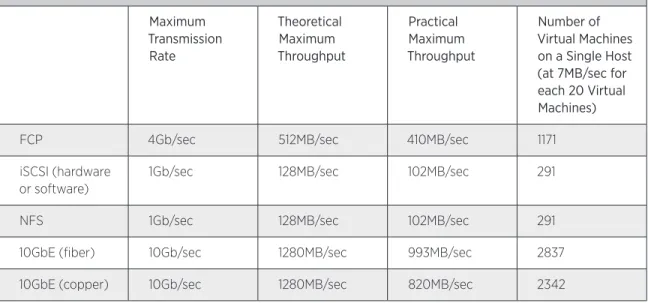
Virtual Machines per Host Based on Storage Protocol shows the maximum throughputs of key storage protocols:
VIRTUAL MACHINES PER HOST BASED ON STORAGE PROTOCOL
Maximum Transmission
Rate
Theoretical Maximum Throughput
Practical Maximum Throughput
Number of Virtual Machines on a Single Host (at 7MB/sec for each 20 Virtual Machines)
FCP 4Gb/sec 512MB/sec 410MB/sec 1171
iSCSI (hardware or software)
1Gb/sec 128MB/sec 102MB/sec 291
NFS 1Gb/sec 128MB/sec 102MB/sec 291
10GbE (fiber) 10Gb/sec 1280MB/sec 993MB/sec 2837
10GbE (copper) 10Gb/sec 1280MB/sec 820MB/sec 2342
Table 2: Virtual Machines per Host Based on Storage Protocol
The maximum practical throughputs are well above the needs of a maximized ESX host—128GB of RAM supported in an ESX 4.1 host using 512MB of RAM per Windows guest.
Hardly any production View deployments would use the maximum supported amount of 128GB of RAM per ESX host because of cost constraints, such as the cost of filling a host with 8GB memory SIMMs rather than 2GB or 4GB DIMMs. In all likelihood, the ESX host would run out of RAM or CPU time before suffering a disk I/O bottleneck. However, if disk I/O does become the bottleneck, it is most likely because of disk layout and spindle count (that is, not enough IOPS). The throughput need of the Windows virtual machines is not typically a deciding factor for the storage design.
Note: To present the worst-case scenario of one data session using only one physical path, we did not take link aggregation into account.
VMDK Behavior by Protocol
Both FCP and iSCSI are block-level protocols. ESX has direct access to the disk blocks and controls assembly of blocks into files. Block-level protocols are formatted as VMware VMFS by the ESX hosts and use the ESX file locking mechanism, limited to 32 ESX hosts accessing the same LUN. Block-level protocols also use monolithic, or thick disk, VMDK, in which each VMDK is fully provisioned upon creation, so that a 20GB disk consumes 20GB of space of the block-level storage regardless of the contents of the VMDK.
NFS is a file-level protocol. The NFS appliance controls the file locking and assembly of blocks into files. File-level protocols use the thin disk VMDK format, in which a VMDK is only as large as its contents, so that a 20GB disk containing 10GB of data consumes 10GB on the NFS storage device. ESX can support up to 32 NFS datastores on a single host.
FCP-attached LUNs formatted as VMware VMFS have been in use since ESX version 2.0. Block-level protocols also allow for the use of raw disk mappings (RDM) for virtual machines. However, RDMs are not normally used for Windows XP or Windows 7 virtual machines because end users do not typically have storage requirements that would necessitate an RDM. FCP has been in production use in Windows-based datacenters for much longer than iSCSI or NFS.
VMware introduced iSCSI and NFS support in ESX 3.0.
iSCSI, being a block-level protocol, gives the same behavior as FCP but typically over a less expensive medium (1Gb/sec Ethernet). iSCSI solutions can use either the built-in iSCSI software initiator or a hardware iSCSI HBA. The use of software initiators increases the CPU load on the ESX host. iSCSI HBAs offload this processing load to a dedicated card (as Fibre Channel HBAs do). To increase the throughput of the TCP/IP transmissions, you should use jumbo frames with iSCSI. VMware recommends a frame size of 9000 bytes.
NFS solutions are always software driven. As a result, the storage traffic increases the CPU load on the ESX hosts.
For both iSCSI and NFS, TCP/IP offload features of modern network cards can decrease the CPU load of these protocols.
If you use either iSCSI or NFS, you might need to build an independent physical Ethernet fabric to separate storage traffic from normal production network traffic, depending on the capacity and architecture of your current datacenter network. FCP always requires an independent fiber fabric, which may or may not already exist in a particular datacenter.
Use of Existing Infrastructure
To decide whether to use existing storage infrastructure or acquire new infrastructure (fabric or array), you should evaluate the capacity and capabilities of any existing devices in your datacenter and consider the answers to the following questions:
• Do you have a storage array that is on the ESX 4.1 hardware compatibility list?
• Does the existing array have enough IOPS capacity for the anticipated number of virtual machines? • Does the existing array have enough storage capacity for the virtual machines?
• Do you have a fabric (Ethernet or Fibre Channel) that can support the anticipated number of ESX hosts? • Do you have a VMware Infrastructure environment for virtualized servers? If so, does the storage have enough
capacity to support the new VMware View environment?
Final Protocol Choice
The final choice of protocol for VMware ESX storage supporting a VMware View implementation is often more financial and psychological than technical. If you need to purchase a new fabric and array, the total cost of ownership and return on investment become leading factors in your decision about the storage fabric and array. If you can use an existing fabric and array, the new VMware View implementation inherits the technical features of that existing infrastructure.
Storage Technology Options
VMware View gives you six main options for storage:
• Standard shared storage, similar to that used for basic virtual server deployments • Storage-level thin provisioning, at either the virtual machine or the volume level • Single-instancing, also known as data deduplication
• Storing only the user data and booting the operating system from the network • Local storage
• Tiered storage
By using one or more of these technologies properly, you can reduce the overall storage requirements of most VMware View environments. Which technology you use in a given environment will depend on your organizational availability and performance requirements.
Standard Shared Storage
VMware View with standard shared storage resembles the storage usage of typical virtual servers. A logical unit number (LUN) is created from a volume on shared storage and presented to the ESX host, which uses the LUN to store fully provisioned individual virtual machines.
VMware View workloads using standard shared storage need larger LUNs than those used for virtual servers. Desktop workloads typically have much lower I/O needs than server workloads, but desktops often have large footprints compared to their I/O needs, especially when application sets are installed in the template virtual machines. A server LUN might be 300GB, whereas a desktop LUN might be up to 500GB. However, you may need smaller LUN sizes for array-based snapshots with VMware View because the use of array-based snapshots can affect storage subsystem performance.
You should use standard shared storage with VMware View only for certain types of desktops with unique needs, such as a one-off application set for a unique user, for information technology staff, or perhaps in small VMware View implementations that require only a limited number of desktops.
Thin Provisioning
Thin provisioning is a term used to describe several methods of reducing the amount of storage space used on the storage subsystem. Key methods are:
• Reduce the white space in the virtual machine disk file.
• Reduce the space used by identical virtual machines by cloning the virtual disk file within the same volume so that writes go to a small area on the volume, with a number of virtual machines sharing a base image. • Reduce the space used by a set of cloned virtual machines by thin cloning the entire volume in the shared
storage device. Each volume itself has a virtual clone of the base volume.
Thin provisioning starts with some type of standard shared storage. You can then clone either the individual virtual machines or the entire volume containing the virtual machines. You create the clone at the storage layer. A virtual machine’s disk writes might go into some type of snapshot file, or the storage subsystem used for the clones of individual machines or volumes might track block-level writes.
You can use thin provisioning methods in many areas, and you can layer or stack reduction technologies, but you should evaluate their impact on performance when used separately or in combination. The layered approach looks good on paper, but because of the look-up tables used in the storage subsystem, the impact may be undesirable. You must balance savings in storage requirements against the overhead a given solution brings to the design.
Virtual Machine White Space
Reduction of white space in the virtual disk file refers to the removal of unused space in the virtual disk file. The storage used by a virtual machine is based on the actual amount of data in the disk file. For example, using ESX, a VMDK file on an NFS mount is provisioned as thin by default, so a 40GB VMDK with 24GB of data uses 24GB of storage when provisioned as thin.
Thin Provisioning Individual Virtual Machines
Sharing a base VMDK virtual disk at the hypervisor level is an option that has been technically possible for some time. This approach allows you to leverage a base VMDK file with multiple virtual machine snapshots and does not require manual configuration or customization of .vmx files. This approach leverages virtual machine snapshots and the result is an excellent reduction in storage without the aid of any other storage reduction techniques.
You can also share the base image within the storage subsystem. As with sharing the VMDK within a VMFS volume at the hypervisor level, some storage devices are capable of sharing a base VMDK image file at the storage layer. Sharing at the storage layer instead of using a snapshot within a VMFS volume offers much greater scalability. You might be able to achieve a ratio of 1:20 or higher.
File Layer Thin Provisioning Tips
• Configure the guest operating system so it can be duplicated by using Microsoft’s Sysprep utility.
• Pay close attention to how individual virtual machines write data. For example, do not install large applications in the individual virtual machine clones. Go back to the base image and update it instead.
• Understand Windows page file usage. Some virtual machine usage scenarios can cause abnormal array-based snapshots and performance issues.
Thin Provisioning Entire Datastores
Leveraging thin provisioning at the datastore level opens up additional possibilities for storage reduction. You can clone the entire datastore, rather than the individual virtual machine, and represent it to the ESX cluster as a different datastore. The clone, however, does not actually use twice the storage if it is virtually cloned in the storage subsystem of the shared storage device.
The idea behind this approach is that you virtually clone an original base golden datastore so a datastore with multiple (20 or more) virtual machines can be virtually cloned several times over. You can then power on and use each virtual machine individually, while using only the common storage footprint of the original base golden datastore for all 100 or more virtual machines.
This type of thin provisioning is heavily dependent on the storage manufacturer’s snapshot technology. Some storage vendors provide better performance than others.
Datastore Layer Thin Provisioning Tips
• For VMFS datastores, enable the enableresignature option in vCenter to use a cloned datastore.
• As with file layer provisioning, guest operating systems in the virtual machines in the base datastore must be in a state to be duplicated. Use Sysprep, and have the virtual machine ready to make modifications when it powers on, including a new host name, SID, domain membership, and networking information.
• Performance will not be linear. Multiple base image datastores might be necessary. Scalability of clones per base datastore greatly depends on the storage vendor’s snapshot method and efficiency.
Thin Provisioning Summary
Expect to see several methods of thin provisioning working together to compress View storage. In the future, it will be possible to leverage image-level thin provisioning with datastore virtual cloning. Scalability of these solutions is very promising, especially with NFS. However, little accurate field data is available for real-world scenarios under View.
Single-Instancing
The concept of single-instancing, or deduplication, of shared storage data is quite simple: The system searches the shared storage device for duplicate data and reduces the actual amount of physical disk space needed by matching up data that is identical. Deduplication was born in the database world, where the administrators created the term to describe searching for duplicate records in merged databases. In discussions of shared storage, deduplication is the algorithm used to find and delete duplicate data objects: files, chunks, or blocks. The original pointers in the storage system are modified so that the system can still find the object, but the
physical location on the disk is shared with other pointers. If the data object is written to, the write goes to a new physical location and no longer shares a pointer.
Varying approaches to deduplication exist, and the available information about what deduplication offers front-line storage can be misleading.
Regardless of the method, deduplication is based on two elements: hashes and indexing.
Hashes
A hash is the unique digital fingerprint that each object is given. The hash value is generated by a formula under which it is unlikely that the same hash value will be used twice. However, it is important to note that it is possible for two objects to have the same hash value. Some inline systems use only the basic hash value, an approach that can cause data corruption. Any system lacking a secondary check for duplicate hash values could be risky to your VMware View deployment.
Indexing
Indexing uses either hash catalogs or lookup tables.
Storage subsystems use hash catalogs to identify duplicates even when they are not actively reading and writing to disk. This approach allows indexing to function independently, regardless of native disk usage. Storage subsystems use lookup tables to extend hash catalogs to file systems that do not support multiple block references. A lookup table can be used between the system I/O and the native file system. The disadvantage of this approach, however, is that the lookup table can become a point of failure.
Applications for Deduplication
In the backup storage market, deduplication has obvious benefits. The potential for duplicate data is huge. Ratios of 20:1 and higher are common. Identical data in backups is even more pronounced, and the speed at which the deduplication must take place is often much slower than in the case of front-line virtual machine workloads.
Two methods of deduplication are in-line (on-the-fly) deduplication and post-write deduplication. Which you choose depends greatly on the type of storage you use. Post-write deduplication is the primary method you should consider as a part of a View architecture. In-line deduplication is not yet fast enough to provide appropriate speed for a larger infrastructure. It is designed primarily for backup applications.
In-line deduplication, deployed today for backups and archiving, keeps track of object records virtually and writes only the nonduplicate blocks to a (typically proprietary) back-end file system. It requires two file systems, one on the front and one on the back. If must search out duplicate objects before writing the data to disk and must accomplish this very quickly. As processor computing power increases and solid state disk costs decrease, in-line deduplication will become an increasingly viable option for front-line storage.
Vendors are making quite a bit of effort in this space today. However, in-line deduplication still lacks the maturity needed for View storage.
With post-write deduplication, the deduplication is performed after the data is written to disk. This allows the deduplication process to occur when system resources are free, and it does not interfere with front-line storage speeds. However, it does have the disadvantage of needing sufficient space to write all the data first and then consolidates it later, and you must plan for this temporarily used capacity in your storage architecture.
Network-Booted Operating Systems
Booting an operating system directly onto a virtual or physical device across the network is a relatively new concept. Only in the last few years has the technology been made available as an alternative to the standard approach that uses an installed operating system.
This technology allows a device to boot the operating system over a network from either a one-to-one image or a shared image. The operating system’s disk drive is an image file on a remote server. A virtual machine typically would use PXE to bootstrap to the imaging server, which would then provide the correct virtual disk to the booting machine across the network.
The protocol used for this technology is very similar to iSCSI (originally local SCSI wrapped in a TCP/IP packet) designed for use on a network.
Streaming adds another consideration when the imaging server serves up the virtual disk as a read-only image, with a private write disk for each virtual machine instance. This write disk holds everything that has been changed since the computer booted. You can store the cache in various places, including the virtual machine’s RAM, the local hard disk, or a file on the network file server. When the virtual machine powers off, the changes disappear unless the image is configured to keep the write image on a file server.
You can also set up a private one-to-one mapping. You still must provide storage for the individual disk files, but in this case, the storage is on the imaging server.
Advantages of Booting from the Network
• SAN storage space savings—Each virtual machine needs only a very small VMDK so it appears to have the local disk it needs to function.
• Speed—Deployment of new machines is nearly instantaneous.
• Flexibility—You can very easily change what the virtual machine is booting and seeing and very easily update one base image that deploys many individual virtual machines in a pool.
Disadvantages of Booting from the Network
• No capability for working off-line today. • Support only for nonpersistent pools by default. • Heavy network traffic.
• Increased server hardware requirements.
• Scaling issues for each imaging server in larger deployments.
• Access issues because private images reside in one place. If the imaging server fails, those desktops are not accessible, and thus you may not meet the SLA for the desktop virtual machine.
Local Storage
You can use local storage (internal spare disk drives in the server) but VMware does not recommend this approach. Take the following points into consideration when deciding whether to use local storage:
• Performance does not match that of a commercially available storage array. Local disk drives might have the capacity, but they do not have the throughput of a storage array. The more spindles you have, the better the throughput.
• VMware VMotion™ is not available for managing volumes when you use local storage. • Local storage does not allow you to use load balancing across a resource pool. • Local storage does not allow you to use VMware High Availability.
• You must manage and maintain the local storage and data.
• It is more difficult to clone templates and to close virtual machines from templates.
Tiered Storage
Tiered storage has been around for a number of years and has lately been getting a serious look at as a way to save money. Ask what the definition of tiered storage is, and you’re likely to get answers from ‘a method for classifying data’ to ‘implementing new storage technology.’ Tiered storage is really the combination of the hardware, software and processes that allow companies to better classify and manage their data based on its value or importance to the company.
Data classification is a very important part if not the most important part of any company’s plans to implement a tiered storage environment. Without this classification, it is virtually impossible to place the right data in the appropriate storage tiers. For example, you would want to put the most important data on fast, high-I/O storage i.e. solid state disk drives (SSDD) or Fibre Channel, and less critical or accessed data onto
less-expensive drives such as SAS or SATA. By making this change you will likely experience quicker access and get better performance out of your storage, as you have effectively removed those users accessing non-critical data and the data itself from those storage devices. In addition, faster networks allow for faster access that will further improve responsiveness.
There is no one ‘right’ way to implement a tiered storage environment. Implementations will vary depending on a company’s business needs, its data classification program and budget for the hardware, software and ongoing maintenance of the storage environment.
Storing View Composer Replicas and Linked Clones on Separate Datastores
VMware View 4.5 offers a tiered storage option. You can place View Composer replicas on SSDD and linked clones on less-expensive drives like SATA. By taking advantage of the new tiered storage option, intensive operations such as provisioning many linked clones at once can be speeded up.
As an example, you can store the replica virtual machines on a solid-state disk-backed datastore. Solid-state disks have low storage capacity and high read performance, typically supporting 20,000 I/Os per second (IOPS). They are also expensive. However, View Composer creates only one replica for each View Composer base-image snapshot on each ESX cluster, so replicas do not require much storage space. A solid-state disk can improve the speed at which ESX reads a replica’s OS disk when a task is performed concurrently on many linked clones.
Linked clones can be stored on more traditional, spinning media-based datastores. These disks provide lower performance, typically supporting 200 IOPS. They are cheap and provide high storage capacity, which makes them suited for storing the many linked clones in a large pool. ESX does not need to perform intensive simultaneous read operations on a linked clone.
Configuring replicas and linked clones in this way can reduce the impact of I/O storms that occur when many linked clones are created at once.
Note: This feature is designed for specific storage configurations provided by vendors who offer high-performance disk solutions. Do not store replicas on a separate datastore if your storage hardware does not support high-read performance.
In addition, you must follow certain requirements when you select separate datastores for a linked-clone pool: • If a replica datastore is shared, it must be accessible from all ESX hosts in the cluster.
• If the linked-clone datastores are shared, the replica datastore must be shared. Replicas can reside on a local datastore only if you configure all linked clones on local datastores on the same ESX host.
Note: This feature is supported in vSphere mode only. The linked clones must be deployed on hosts or clusters running ESX 4 or later.
Availability Considerations for Storing Replicas on a Separate Datastore or
Shared Datastores
An additional consideration to keep in mind is the availability of the pool. When you store replicas on the same datastores as linked clones, View Composer creates a separate replica on each datastore to enhance availability. If a datastore becomes unavailable, only the linked clones on that datastore are affected. Linked clones on other datastores continue running.
When you store replicas on a separate datastore, all linked clones in the pool are anchored to the replicas on that datastore. If the datastore becomes unavailable, the entire pool is unavailable.
To enhance the availability of the linked-clone desktops, you can configure a high-availability solution for the datastore on which you store the replicas.
Storage Array Decisions
When you decide on a storage array for a VMware View implementation, you need to choose the disk type and RAID type you will use. In addition, you might consider snapshots, clones, replication, and manageability. Current disk options are:
• Fibre Channel (FC) • Serial ATA (SATA)
• Serial Attached SCSI (SAS)
These choices represent the protocol used by the storage array, not between the array and the ESX hosts. You must also choose disk speed, usually between 7,200RPM and 15,000RPM. You can often make your disk protocol and speed choices on the basis of your budget, as long as the capacity (in both IOPS and gigabytes of space needed) can support the anticipated size of the View deployment.
Current RAID level choices are: • RAID 4
• RAID 5 • RAID 1+0 • RAID 6
• RAID-DP (NetApp only) • MetaRAID (EMC Clariion only) • vRAID (HP EVA only)
Your choice of RAID type depends largely on the storage array you purchase. Usually, you make the purchase decision for reasons other than the supported RAID types in a particular mid-tier storage solution. All mid-tier storage arrays can achieve high performance with high redundancy in various ways. As with the individual disk choice, as long as the RAID choice provides the desired IOPS speed, gigabytes of capacity, and disk failure redundancy, you can use any RAID listed above.
Note: A maximum of 32 ESX hosts can access the same set of 256 block-level assigned LUNs or the same set of 32 NFS datastores.
Increasing Storage Performance
The following sections explain different technologies for increasing storage performance. One way to increase storage performance is to reduce the response time (aka latency) that is needed to satisfy a given IO request. High performance and the falling cost of Flash technology have lead to some innovative ways for creating additional cache, thus increasing storage performance. In addition Flash-based technologies help reduce the environmental impacts by reducing floor space, power, and cooling associated with spinning disk.
Solid State Drives
What is a Solid State Drive?
A solid-state drive (SSD), also called a flash drive, is a storage device that uses Flash memory to store persistent data. A SSD differs from a hard disk drive (HDD), in that there are no spinning disks or movable read/write heads. Because there are no moving parts, SSDs are quieter and less susceptible to physical shock. SSDs use the same interface as HDDs and have lower access time and latency, making them ideal for writing to and reading data quickly.
Flash memory refers to a particular type of EEPROM (Electronically Erasable Programmable Read Only Memory). It can maintain stored information without the need of a power source. Flash memory differs from a typical EEPROM, in that it can erase its data in entire blocks, which benefits applications that require frequent updating of large amounts of data.
Dell’s Enterprise Hard Drives and Over Provisioning
Dell has several offerings that include SSD drives. As described in their product overview on SSD drives, “Understanding the basics of enterprise-class solid state drives allows customers to measure apples-to-apples
when comparing solutions.” Dell explains that “SLC Flash (Single Level Cell) can store one bit per cell, while MLC Flash (Multi Level Cell) can store multiple bits of information per cell.” They go on to explain that “SLC based Flash has a write endurance capability roughly 10X of what MLC Flash is capable of.”
Over Provisioning is used to increase the write performance of SSDs. Dell explains that “To re-write an area of an SSD that has already been written the data must be erased and then written.” To minimize this effect, Dell’s SSD drives also use a technique called Over Provisioning. “This practice keeps native flash capacity beyond the use defined capacity and utilizes the additional space as a scratch-pad of source to quickly put down application write data on areas of flash that are already in an erased state. The SSDs perform cleanup functions of this over provisioned flash space during time periods typically not impacting application performance.” Dell has several product lines that take advantage of the SLC based Flash and Over Provisioning. Dell’s solutions include: Dell PowerEdge, EqualLogic and Dell-EMC SSD solutions.
EMC’s FAST Cache
What is FAST Cache?
FAST cache is used in conjunction with EMC’s FAST (Fully Automated Storage Tiering). FAST automatically moves active data to high-performance storage tiers and inactive data to lower-cost/high-capacity storage tiers by continuously monitoring and identifying the activity level of the data. FAST cache is a feature
developed by EMC that optimizes the performance of its storage systems by extending the functionality of the DRAM cache by mapping frequently accessed data to the Flash drives which provides very large capacities per drive as compared to DRAM capacities. FAST cache does not require additional hardware and uses existing enterprise Flash drives to extend the cache.
How is FAST Cache implemented?
FAST Cache uses existing Flash drives with capacities ranging from 73 GB to 2 TB as discussed in EMC’s CLARiiON and Celerra Unified FAST Cache – A Detailed Review white paper. FAST Cache is created in RAID-protected read/write mode and the capacity options depend on the storage-system model and the number and types of installed Flash drives.
Can the FAST Cache be configured?
As mentioned above, FAST continuously monitors the data and identifies the activity level, then automatically moves the active data and inactive data to the appropriate storage tier based on a policy. It is the policy settings in FAST that allow administrators to control and manage the automated activity.
Basically, the FAST Cache keeps the most heavily accessed data on the Flash drives for as long as possible. As discussed in EMC’s CLARiiON and Celerra Unified FAST Cache white paper, when new data needs to be copied into FAST Cache, a Least Recently Used (LRU) algorithm decides which data should be moved out of FAST Cache. This ensures that the frequently accessed data stays in FAST Cache for as long as possible.
Configuring FAST Cache is a nondisruptive online process. As detailed in EMC’s CLARiiON and Celerra Unified FAST Cache white paper, it uses the existing memory-allocation interface and does not use host (server) cycles. You create FAST Cache, enable it on storage volumes, and manage it through Unisphere. No user intervention is required to enable applications to start seeing the performance benefits of FAST Cache.
What products support FAST Cache?
In CLARiiON and Celerra unified storage systems, starting with FLARE® release 30, you can use Flash drives as FAST Cache.
FAST Cache capacities range from 73 GB to 2 TB.
NetApp Virtual Storage Tiering
What is Flash Cache (PAM II)?
NetApp Flash Cache helps boost performance of random read-intensive virtualized workloads without adding high-performance, expensive SSD drives. This intelligent read cache speeds access to data, reducing latency by a factor of 10 or more compared to spinning disk. Flash Cache also provides comparable performance to SSD without the complexity of having to move data to yet another tier of storage. Active data automatically flows into Flash Cache because every volume and LUN behind the storage controller can use the cache. This is the concept of Virtual Storage Tiering. NetApp Virtual Storage Tiering works like this: when a read request comes from an ESX server to the storage controller, main memory and Flash Cache are checked to see if the block of data already exists. If it does not exist in either cache, the data is read from disk and the cache now has a copy of the data. The unique technology is simply this: data is deduplicated at the block level on disk and thus is also deduplicated in the cache. So when events like boot storms or login storms occur, the impact of these events is negated due to the cache and deduplication.
How is the Flash Cache implemented?
Flash Cache has a hardware and software component, the Flash Cache module and the FlexScale software license. The Flash Cache module is a PCI Express device that contains 256GB or 512GB of SLC memory each and the storage controllers have the capability to have up to 8TB of additional cache.
Can the Flash Cache module be configured?
FlexScale, the software component of the Flash Cache solution, contains the caching policies implemented to optimize small-block, random read access. The caching policies can be changed to meet specific requirements. There are three modes of operation for the Flash Cache: Metadata Only Mode, Normal User Data, and Low
Priority Data. The default out-of-the-box configuration for FlexScale is Normal User Data, which combines Metadata and Normal User data modes. This is the optimal setting for virtualized workloads.
How can I prioritize what stays in the cache?
FlexShare is a solution that provides Data ONTAP a hint about how to manage the Virtual Storage Tiering for a volume.
The cache policy can be one of the following values:
• Keep – This value tells Data ONTAP to wait as long as possible before reusing the cache buffers. This value can improve performance for a volume that is accessed frequently, with a high incidence of multiple accesses to the same cache buffers. This would be the value one would use when deploying technologies such as linked clones. The caching policy of keep would be set on the volume that contains the master images or templates, thus pinning the data into cache.
• Reuse – This value tells Data ONTAP to make buffers from this volume available for reuse quickly. You can use this value for volumes that are written but rarely read, such as database log volumes, or volumes for which the data set is so large that keeping the cache buffers will probably not increase the hit rate.
• Default – This value tells Data ONTAP to use the default system cache buffer policy for this volume. What products support Flash Cache?
The Flash Cache modules are supported on several of NetApp’s FAS/V series storage systems. Flash Cache modules are available in either 256GB or 512GB. Depending on the model, the maximum number of Flash Cache PAM modules supported per controller is anywhere from 2 to 16. This will enable an extended cache memory of 512GB to 8TB depending on the storage system.
NetApp has developed a software package to help you determine if your storage systems will benefit from added cache via Flash Cache modules. Predictive Cache Statistics (PCS) software is currently available in Data ONTAP 7.3 and later releases will allow you to predict the effects of adding the cache equivalent of two, four or eight times the system memory.
Conclusion
When you assess the storage needs for your VMware View implementation, be sure you cover the following points:
• Base your design choices for a production View implementation on an understanding of the disk needs of the virtual machines. Windows XP or Windows 7 clients have radically different needs from virtual machines that provide server functions. The disk I/O for clients is more than 90 percent read and is rather low (7MB/ sec or 112 IOPS per 20 virtual machines). In addition, very little disk space is needed beyond the operating system and application installations because all end-user data should be stored on existing network-based centralized storage, on file servers, or on NAS devices.
• When you understand the disk size, throughput, and IOPS needs of a given View deployment, you have the information you need to choose storage protocol, array type, disk types, and RAID types. Thin provisioning, data deduplication, and cloning can dramatically lower the disk space required.
• The most important consideration in storage decisions is often financial rather than technical. Consider these questions: Can existing data center resources be reused? What are the value proposition and return on investment of acquiring an entirely new storage environment?
About the Author
Fred Schimscheimer is a Senior Technical Marketing Engineer at VMware. In this role, he works as part of the product marketing team as an expert in storage and workloads for virtual desktop solutions.
References
Dell’s Enterprise Hard Drives Overview
http://www.dell.com/content/topics/topic.aspx/global/products/pvaul/topics/en/hard-drives?c=us&cs=555&l =en&s=biz&~tab=2
EMC CLARiion and Celerra Unified FAST Cache – A Detailed Review
http://www.emc.com/collateral/software/white-papers/h8046-clariion-celerra-unified-fast-cache-wp.pdf
EMC Glossary – Fully Automated Storage Tiering (FAST) Cache
http://www.emc.com/about/glossary/fast.htm http://www.emc.com/about/glossary/fast-cache.htm
EMC Demo
http://www.emc.com/collateral/demos/microsites/mediaplayer-video/demo-fast.htm
NetApp Tech OnTap – Boost Performance Without Adding Disk Drives
http://www.netapp.com/us/communities/tech-ontap/pam.html
NetApp Flash Cache (PAM II)
http://www.netapp.com/us/products/storage-systems/flash-cache/
NetApp Flash Cache (PAM II) – Optimize the performance of your storage system without adding disk drives
http://media.netapp.com/documents/ds-2811-flash-cache-pam-II.PDF
NetApp Flash Cache (PAM II) Technical Specifications