Corresponding Author: K.Vinoth Babu, School of Electronics Engineering, VIT University, Vellore, Tamil Nadu, INDIA E-mail: [email protected]
177
Spectral Efficiency Improvement in MIMO OFDM Systems with Interleave Division
Multiplexed (IDM) Space Time Block Coding (STBC) Scheme
K.Vinoth Babu, Dr.G. Ramachandra Reddy, Utpal Sharma
Assistant Professor, Senior Professor, M.Tech (Communication Engineering) School of Electronics Engineering, VIT University, Vellore, Tamil Nadu, INDIA
Abstract: MIMO OFDM systems are very popular in 4G wireless standards because of higher spectral
efficiency and reliable transmission. Long Term Evolution- Advanced (LTE-A) standards use MIMO with a maximum of 8x8 antennas in the downlink and 4x4 antennas in uplink. In this paper a simple 2x1 MIMO system with Alamouti coding is considered. Orthogonal Space Time Block Codes (OSTBC) is mainly used to achieve space and time diversity which improves the reliability of the system. In the conventional schemes based on the average channel gains adaptive modulated symbols are Alamouti coded and transmitted. In adaptive modulated STBC, when different modulation schemes are employed in transmitting antennas decoding complexity increases. This paper proposes a new technique called Interleave Division Multiplexing (IDM) which is an alternate to the conventional adaptive modulation. The results show that proposed method improves the spectral efficiency of MIMO system and reduces the decoding complexity.
Key words: Space Time Diversity (STD), Interleave Division Multiplexing (IDM), Space
Time-Trellis Code (STTC).
INTRODUCTION
MIMO based wireless communication system design is the hot research topic. MIMO offers Spatial Multiplexing (SM) and diversity gain features than the traditional SISO systems which makes the system to have higher capacity and reliability. Receive diversity with Maximal Ratio Combining (MRC) offers very good diversity gain. When pre coding is applied in the transmitter side, transmit diversity will also give similar performance like receiver diversity. But for pre coding, the Channel Quality Information (CQI) should be known at the transmitter side. Channel estimation error and channel information feedback delay have significant effect in beam forming which makes transmit diversity a unreliable one. One of the simplest and most useful STBC techniques is Alamouti scheme (Siavash M. Alamouti, 1998). It exploits transmit diversity without using CQI in the transmitter side. Alamouti coding offers almost similar performance like receive diversity.
The multipath characteristics of the environment cause the MIMO channel to be frequency selective. Frequency selective fading causes Inter Symbol Interference (ISI) and degradation in system performance. Very complex equalizers are required to compensate the effects of the frequency selective fading. OFDM is the best possible solution for frequency selective fading. OFDM can turn a frequency selective fading channel into a set of parallel flat fading channels and renders simple one tap equalization for each subcarrier. Because of this MIMO systems are always combined with OFDM systems to offer very high data rate in the frequency selective fading environment (Ramjee Prasad, 2004).
Previously in STBC fixed modulation schemes were employed on both the transmitting antennas without caring much about the channel. In adaptive STBC, channel is estimated for both transmitting antennas and average channel gain is calculated. Based on the average channel gain both transmitting antennas employ same modulation (Ezio Biglieri et al., 2007). In both the cases there is a chance of transmission of higher modulated data over a poor channel condition and vice versa, which causes poor spectral efficiency. If adaptive STBC use different modulation in different antennas, decoding complexity increases.
In this paper we have proposed the adaptive STBC based on IDM. When channel conditions for the antennas are different and uncorrelated, we use a different modulation for both antennas by the IDM which gives an improvement in spectral efficiency and also reduces the decoding complexity.
Space Time Diversity:
178
single receiving antenna. Figure 1 shows the representation of simple Alamouti scheme (Siavash M. Alamouti, 1998).
Fig. 1(a): Simple STBC.
Fig. 1(b): Block diagram of STBC-OFDM.
In figure 1(a), at a given symbol period two symbols are transmitted from the two antennas. Let X1 and
2
X be the symbols transmitted from antennas one and two respectively during first symbol period. During the next symbol period symbol X*2 is transmitted from antenna one and
* 1
X
is transmitted from antenna two, where * represents the complex conjugate operation, g &g1 2are channel gains of antenna 1 and 2 respectively and Tsis symbol duration.
For STBC OFDM systems single carrier symbols mentioned in the above figure 1(a) is replaced by the OFDM symbols as shown in figure 1(b).
Interleave Division Multiplexing:
IDM has been studied recently as special case of Bit Interleaved Coded Modulation (BICM). Earlier works show that IDM systems offer better performance over AWGN and quasi static MIMO channels. IDM is convenient for adaptive modulation and it can be used to construct STD through which high diversity and multiplexing gain can be achieved in MIMO system. Basically IDM is used for the conversion of higher modulated symbol to lower modulated symbol in adaptive STBC modulation. The IDM modulated symbol can be defined as (Li Ping et al., 2009).
i
Q-1 b i i=0
X=
a (-1) (1)where Q is number of bits in a symbol, ai is ith power factor and bi is ith binary digit of input.
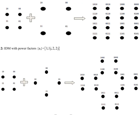
In this paper we assume only two modulation schemes 4 QAM and 16 QAM. Then Q will be 2 or 4. For a particular binary input, based on different power factors different constellation can be constructed. Let the input bits be
1,0,1,0
and power factor
1,1j,2,2j
. 16 QAM modulated symbol for the given binary input can be constructed as follows1 0 1 0
X 1( 1) 1j( 1) 2( 1) 2j( 1)
X 3 3j
179
1 1 0
x 1( 1) 1j( 1)
1
x 1 1j (First 4 QAM Symbol) And
2 1 0
x 2( 1) 2j( 1) 2
x 2 2j (Second 4 QAM Symbol)
The first 4 QAM symbol is for the input {1,0}and second 4 QAM symbol is for the input{1,0}. When these two lower order modulated symbols are added, equivalent higher modulated symbol can be constructed( 1 1j) ( 2 2j) ( 3 3j) .
The same procedure can be repeated for different binary input values. IDM procedure is clearly explained in figure 2. By varying the power factor alone, different constellations can be constructed for 4 QAM and 16 QAM. Two other constellations with power factors {1,1j, 2(1 1j), 2(1 1j)} & {1,1j,1.4717,1.4717 j} are shown in figure 3 and figure 4.
Fig. 2: IDM with power factors {ai}=
1,1j,2,2j
Fig. 3: IDM with power factors {ai}={1,1j, 2(1 1j), 2(1 1j)}
The minimum Euclidean distance of three different 16 QAM modulation schemes are found to be 2, 1.17 and 0.9434 respectively. Because of high minimum Euclidean distance the 16 QAM modulation with power factors
1,1j,2,2j
exhibits good BER performance then the other two power factors. Due to this reason throughout the paper IDM with power factor
1,1j,2,2j
is used.The Proposed IDM-STBC-OFDM System:
180
Fig. 4: IDM with power factors {ai}= {1,1j,1.4717,1.4717 j}
Encoding:
Consider that the proposed system model which has two transmitting and one receiving antenna. At a given time period, symbols are transmitted from each antenna, and those symbols are passed through different i.i.d. channels. To explain the model it is also assumed that antenna 1 has a better channel condition compared to antenna 2 i.e.g1 g2 . It is also assumed that the channel condition should be same for two symbol periods.
Since the channel for antenna 1 is good, higher modulated symbol X1 is transmitted from antenna 1. But the
channel for antenna 2 is poor, using IDM equivalent multiple lower modulated symbols are generated and it is transmitted from M contiguous subcarriers of antenna 2 i.e. [x x ...x2,1 2,2 2,M]. The number of contiguous subcarriers (M) can be calculated by
2 1
2 2
log (M ) M=
log (M ) (2)
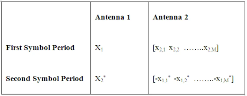
where M1 and M2 are the constellation size of QAM modulated symbols, with M1>M2. Throughout the paper the subscripts 1, 2 indicates antenna 1 & 2 respectively. During the next symbol period the combined higher
modulated symbol * *
2 2,1 2,2 2,M
X [x x ...x ] is transmitted from antenna one and the divided lower modulated
symbols * *
1 1,1 1,2 2,M
-X [x x x ] is transmitted from antenna 2 (Junwoo Jung et al., 2010). For simplicity we have considered only two modulation schemes like 16-QAM and 4-QAM in this paper. Thus
1 2
M 16, M 4 and M 2 .Two consecutive subcarriers are allocated to carry IDM lower modulated symbols in antenna 2.
The transmission sequence of proposed scheme is shown in figure 5
Fig. 5: Transmission Sequences of Proposed Scheme with 16QAM and 4QAM Modulation.
Decoding:
Here we make an assumption that antenna 2, at which lower modulated symbol is transmitted over M subcarriers, has the highly correlated channel coefficients for those subcarriers. The received signal with IDM method can be given as.
1
1 2,1 2,2
1 1
2,1
* * *
2 2 1,1 1,2 2
2,2
g
X x x
r ρ
= g +
r X -x -x g ρ
181
where r1 & r2 are the received signals at symbol period 1 and 2 respectively. 1&2 are the thermal noise added at symbol period 1 and 2 respectively. g & g2,1 2,2 are the channel gains of two contiguous subcarriers of antenna 2.
The received signal at first symbol period is given as
1 1 1 2,1 2,1 2,2 2,2 1
r =X g +x g +x g +ρ
(4) Since the neighbouring sub channels are almost equal
^
2,1 2,2 2
g g g (5)
The equation (4) can be simplified as
^
1 1 1 2 2,1 2,2 1
r X g g x x (6)
With IDM, the lower order symbols can be combined to make higher order modulation
2 2,1 2,2
X x x
* * *
1 1,1 1,2
X x x (7)
Substituting (7) in equation (6)
^
1 1 1 2 2 1
r X g X g (8)
Similarly the received signal at second symbol period is given as
* * *
2 2 1 1,1 2,1 1,2 2,2 2
r X g x g x g (9)
Based on the approximations in equation (5) & (7), equation (9) can be reduced to
^
* *
2 2 1 1 2 2
r X g X g (10)
The complex conjugate of equation (10) is
* ^
* * *
2 2 1 1 2 2
r X g X g (11)
Equations (8) and (11) are stacked, such that
1 1 1
* *
2 2 2
r X
r G X
(12) where ^ 1 2 * ^ * 1 2 g g g g G
(13)
From the above equation it is clear that even though we use 2 X 1 MIMO system it will act like a 2 X 2 MIMO system (Yong Soo Cho et al., 2010).
Multiplying with H
G on both sides of the equation (12)
~ 2 ~
1 1 1
2 ~ ~ 2 2 2 g 0 r X X 0 g r (14) where ~ ^ * *
1 1 1 2 2
r r g r g
*
~ ^
*
2 1 2 2 1
r r g r g and
~ ^
* *
1 1 1g 2 g2
*
~ ^
*
2 1g2 2g1
182 Equation (14) can be separated as
~ 2 ~
1 1 1
r g X
~ 2 ~
2 2 2
r g X
(15) From equation (15), the transmitted symbols can be estimated by
~
^ 1
1 r 2
X g
~
^ 2
2 r 2
X g
(16)
Simulation and Results:
The performance of IDM STBC scheme is compared with fixed modulated STBC and adaptive modulated STBC for a channel of an indoor exponential power delay profile model with RMS delay spread of 50 ns. As already mentioned it is assumed that antenna 1 have a better channel condition than antenna 2. Antenna 1 transmits 16 QAM symbols and antenna 2 transmits 4 QAM symbols. The system bandwidth is assumed to be 5MHz. Each OFDM symbol uses 256 subcarriers. The subcarrier bandwidth is 1953 KHz and the target bit error rate (BER) is taken as 103. When both the channel condition are good, conventional adaptive modulated STBC outperforms IDM STBC, because in IDM almost half of the subcarrier are not used in antenna 1. These simulations are averaged over 1000 different channel conditions. The average results are shown in figure 6 & figure 7.
8 9 10 11 12 13 14 15
1.8 2 2.2 2.4 2.6 2.8 3 3.2 3.4 3.6
Antenna 2 SNR(dB)
S
p
e
c
tr
a
l E
ff
ic
ie
n
cy
(
b
it
s/se
c/
H
z
)
At Antenna 1 SNR 17dB
Fixed 4 QAM Fixed 16 QAM Adaptive Modulation Proposed Scheme
Fig. 6: Spectral Efficiency comparison of IDM-STBC with the conventional STBC schemes for average
received SNR of antenna 1 = 17 dB.
183
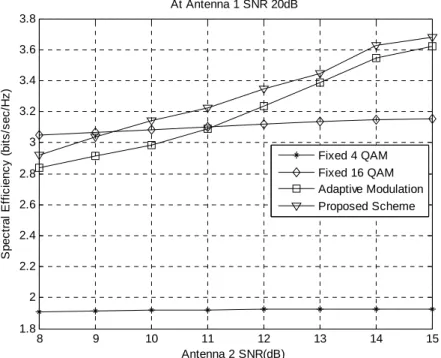
proposed system to offer higher data rate when the transmission bandwidth and number of subcarriers are increased.
8 9 10 11 12 13 14 15
1.8 2 2.2 2.4 2.6 2.8 3 3.2 3.4 3.6 3.8
Antenna 2 SNR(dB)
S
p
e
c
tr
a
l E
ff
ic
ie
n
cy
(
b
it
s/se
c/
H
z
)
At Antenna 1 SNR 20dB
Fixed 4 QAM Fixed 16 QAM Adaptive Modulation Proposed Scheme
Fig. 7: Spectral Efficiency comparison of IDM-STBC with the conventional STBC schemes for average
received SNR of antenna 1 = 20 dB.
Conclusion:
STBC techniques are mainly used for space and time diversity and not for spatial multiplexing. Usually it does not increase the spectral efficiency. This paper discusses the new method IDM-STBC-OFDM technique which increases the spectral efficiency of the conventional STBC OFDM scheme by 1.5% to 3% and it also reduces the complexity of receiver. All the simulation in this paper is carried out under the assumption that the channel is flat fading channel. These results hold good for indoor environments. But in mobile scenarios the channel is frequency selective fading channel. Our future work is to modify the proposed scheme for space frequency block code OFDM (SFBC-OFDM) technique which is supposed to be good for frequency selective fading channel.
REFERENCES
Ezio Biglieri, Robert Calderbank, Anthony Constantinides, Andrea Goldsmith, Arogyaswami Paulraj, H. Vincent Poor, 2007. MIMO Wireless Communication, Cambridge University Press.
Hongwei Yang, Alcatel Shanghai Bell Co., Ltd., 2005. A Road to Future Broadband Wireless Access: MIMO-OFDM-BasedAir Interface, IEEE Communications Magazine, 43(1): 53-60.
Junwoo Jung, Byungchan Kwon, Hyungwon Park, Jaesung Lim, 2010. Superposition-Based Adaptive Modulated Space Time Block Coding for MIMO-OFDM Systems, IEEE Communications Letters, 14(1): 30-32
Li Ping, Jun Tong, Xiaojun Yuan, Qinghua Guo, 2009. Superposition Coded Modulation and Iterative Linear MMSE Detection, IEEE Journal On Selected Areas In Communications, 27(6): 995-1004.
Ramjee Prasad, 2004. OFDM for Wireless Communication System, Artech House.
Siavash M. Alamouti, 1998. A Simple Transmit Diversity Technique for Wireless Communications, IEEE Journal On Select Areas In Communications, 16(8): 1451-1458.