Proceedings of the
Second International Workshop on
Graph and Model Transformation
(GraMoT 2006)
PML: a Transformation Language for Platform Modeling
Tivadar Szemethy and Gabor Karsai
13 pages
Guest Editors: Gabor Karsai, Gabriele Taentzer
Abstract: Modeling the computational platforms is necessary to analyze the exe-cution characteristics of systems developed using a model-based approach. In this paper, we introduce a novel platform modeling language: PML that is based on (a) transformational concepts borrowed from graph transformation languages, and (b) generative concepts from platform modeling, like ’kernel skeleton’. PML relies on higher-level, compact constructs that represent a special case of model transfor-mations, and which are then used to specify platform semantics. The paper also illustrates how PML constructs can be compiled into lower-level constructs of more traditional model transformational languages, such as GReAT.
Keywords:Graph Transformation, Model Transformation, Platform Modeling
1 Introduction
During the implementation of component-based software systems, high-level system models are mapped ontoplatform primitives, just like programs in high-level languages are compiled
into machine code instruction sequences. Platformis defined in the general sense as a collec-tion/abstraction of hardware, software, or middleware primitives and services used to implement the design. The notion of platform is flexible — even within a particular design one can define multiple levels of “platform” abstractions.
For a software engineer, a platform could be an operating system (offering services/primitives such as processes and shared memory), or the CPU with its machine instruction set. For an Internet applications designer, the TCP/IP protocol or XMLRPC might be an useful platform abstraction. For a component-based software system, a component framework, like real-time CORBA can be chosen.
By designing for the right platform abstraction, designers take advantage of existingplatform implementations, reducing the required implementation effort. This definition of the platform concept is discussed by Sangiovanni-Vincentelli and Grant in [SM01].
We assume that a design expressed in a domain-specific modeling language (DSML). Then generating a platform-specific analysis model takes two steps:
1. DSML→Platformtranslation (the “compiler”)
2. Platform→Analysis modeltranslation
The first step maps platform-independent design models into platform-level models. The sec-ond step maps these latter models composed of platform-level primitives onto analysis model structures. For example, this step might generate timed automata models for CPU-level instruc-tions, so that the temporal behavior of the implementation on a particular CPU can be analyzed. Note that the first stage is reusable if CPU-s with the same instruction sets are used, but the sec-ond stage must be different if the timing properties of the same instruction are different across CPU-s.
This paper introduces a language forexplicit platform modeling. With this approach, analysis models are generated at design time, based on the analytical models of different implementation platforms and the design model of the application. Using explicit platform models, designers can evaluate their system’s behavior over multiple platform implementation candidates before committing themselves to one particular implementation.
The Platform Modeling Language described below assists in specifying these platform mod-els; specifically the Platform→Analysis mapping.
In the following text,output modelrefers to the analysis model. DSMis the domain-specific model (or design model), also known as theplatform-independent model orPIM. PSM is the
platform-specific model, which is a refinement of the PIM with platform-specific implementation details.
For example, the DSM can describe an image processing system in a high-level design lan-guage. The PSM describes the system as implemented over a particular dataflow hardware. The analysis model then captures the behavior of this PSM in a (timed or untimed) finite transition system formalism (such as Timed Automata or SPIN [Hol97] model).
2 Previous work
The need for a language to captureexplicitplatform models was first outlined in [SK04], where we argued for the automatic generation of analysis models in design-time. In the above paper, we specified a DSML→Analysis mapping using the GME [LBM+01] modeling environment and the GReAT [KASS03][GZS+05] graph transformation language.
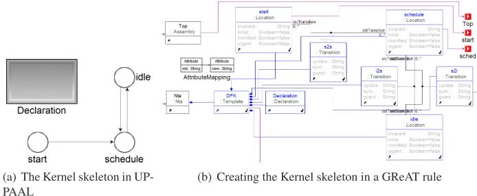
(a) The Kernel skeleton in UP-PAAL
(b) Creating the Kernel skeleton in a GReAT rule
Figure 1: Creating an analysis model fragment in GReAT
In [SK04], both the DSM and analysis models were defined via their respective UML meta-models. Then, GReAT was used to specify transformation rules at the metamodel level. This way, the analysis model, describing the behavior of the system as implemented over a given platform, was obtained from the DSM in one, rather complex, transformation step.
The above paper demonstratedimplicitplatform modeling: the analysis model of the platform was embedded in the transformation specification. The demonstrated transformation was very complex. Since it was specified as a DSML→Analysis mapping, it (implicitly) contained both DSML→Platform and Platform→Analysis mappings. Furthermore, the general-purpose graph transformation language used was a poor fit for some of the recurring transformation tasks, as discussed below.
In the demonstrated example, the platform was a dataflow network. Each actor was mapped onto a timed automaton in the analysis model. These automata were synchronized by an automa-ton modeling the scheduler for the network: theKernelautomaton.
Building the analysis model for a platform actor consisted of two steps:
1. Creating a generic “skeleton” timed automaton with generic states and transitions, such as
startandidle. This “skeleton” was the same for all actors.
2. Extending this “skeleton” with details (states, transitions and conditions) specific to the actor being mapped.
As Fig.1shows, the GReAT rule creating a simple FSM is rather complex and hard to read. This is due to the fact that GReAT rules operate at the metamodel level. For example, creat-ing a simple transition (connection) requires 7 objects in the GReAT rule: {source, destination, connector object, parent object and 3 associations}. Furthermore, it is often the case that switch-ing to a different (e.g. more detailed) analysis model requires changes to the “skeletons” only. Since these are implicitly encoded in the transformation, the changes also require editing the transformation itself.
Sophisticated rule sequencing constructs are typically needed in DSML→Platform ”compiler” transformations, as these tend to be complex (examples for such transformations can be found in [TS06] and related publications). Platform→Analysis transformations are usually much simpler: These transformations typically map each platform “component” (e.g. dataflow actor) onto a cor-responding fragment of the analysis model. The basic structure of the platform-level model and the analysis model is the same, thus a less generic transformation language suffices. Using a less generic language for these transformations could result in simpler, more concise transformation specifications.
The PML language, discussed in the following section, was designed with these considerations in mind.
3 PML: the Platform Modeling Language
PML is a simple, declarative language to specify thePlatform→Analysis model mapping out-lined above. The language supports the building of analysis (target) models by inserting, cus-tomizing and composing target model fragments (called “skeletons”) into the model being built. These skeletons model platform-level structures. PML uses graph patterns to identify, locate and insert these skeletons in the source and target models. Furthermore, PML includes a sim-ple declarative graph transformation language for the composition and customization of these skeletons (“mappings language”).
A PML model consists of 4 basic parts:
1. The UML metamodels for the source (platform) and target (analysis) models that estab-lish a visual language for patterns over models. PML provides an import tool to include GME metamodels into platform models. Additionally, PML models may contain optional
crosslinksdefinitions. Crosslinks are associations that link model elements across different metamodels (i.e. source and target. They are used to simplify subsequent pattern matching by ”marking” certain elements and to maintain state information about the transformation.
2. The construction of the output model starts with the instantiation of the Kernel model
(given as a partial analysis model). This model provides the basic structure of the output model being built. During the construction of the analysis model, this skeleton is extended by attaching PSM-specific elements or modifying attributes.
3. Next,componentsare identified in the source (PSM) model via pattern matching. A target model skeleton is associated with each component in the output model, and instantiated and then customized. The destination within the target model for the copy operation is also designated by a pattern. Crosslinks are automatically generated to link the source component with the corresponding target model structure copied.
4. Finally, the rules in the mappings language further customize and extend the analysis model.
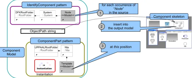
Figure 2: Visualization of the ComponentModel concept
3.1 Component Skeletons
The concept of acomponentis central to PML. Components are a related group of elements in the source model, identifiable by a pattern. The pattern designates a single element to represent the component. Components are mapped onto corresponding structures in the output model. This concept is modeled throughComponentModelsin PML. ComponentModels contain:
• A reference to an analysis model, containing the skeleton.
• A pattern to locate the component within the source model (IdentifyComponent)
• Definitions of one or more target model fragments, onto which the component is mapped in the analysis model (ComponentParts).
The idea of a ComponentModel is visualized in Figure2. In the figure, components are defined asNodeobjects within aSystem. In the skeleton model, a FSM fragment is designated by the
ObjectPathidentifier. This fragment is copied into the output model (as aTemplateobject hier-archy) within theNtacontainer (ComponentPartpattern). Here, theInstantiationcode box can be used to set the attributes of the newly instantiated elements.
3.1.1 Identifying Components
Components in the source (platform) model are identified by anIdentifyComponentpattern. This pattern defines what a component is in terms of source metamodel elements. The pattern also designates a representative element for the component (shaded in the visual language –Node
in the figure). The transformation creates associations between this representative element and the corresponding analysis fragments. Thus, for each analysis fragment the originating source component can be found at a later stage.
3.1.2 Component Parts
corresponding constants or states in the automaton modeling the platform scheduler. In order to facilitate this, ComponentModels may contain one or moreComponentParts. ComponentParts define the following:
• The location of the fragment within the component skeleton model (ObjectPathattribute)
• The destination of the fragment in the analysis model being built.
The destination within the target model is defined by a pattern. The pattern is formulated over target model elements, and designates a single element (shaded grey in the visual language). During the mapping process, this element is created within the target model, and the skeleton is copied into it. In Fig. 2, aTemplate is created for eachNodeand the contents of the skeleton model (shown on the right) are copied into it. The ComponentPart pattern might also contain a procedural code fragment (Instantiationbox), that computes and sets the attributes of the inserted fragments.
Using this approach, the “skeletons” forming the backbone of the analysis model can be com-fortably edited and reviewed within the analysis paradigm.
3.2 Mappings
In addition to the skeleton instantiation language, PML also features a simple graph transforma-tion language (Mappings). This language facilitates fine-grained customization of the analysis model, after the skeleton instantiations have taken place.
The language uses rewriting rules based on graph patterns. The patterns are UML class diagram-like graph patterns. Typing is implemented by the nodes being references to metamodel elements.
A PML mapping identifies PSM patterns throughfilter patterns(the left-hand side, LHS), and maps them onto analysis structures as specified byaction patterns(the right-hand side, RHS). Filter patterns can be annotated by C++ code snippets as boolean-valuedguardfunctions over the attribute values of pattern elements.
A filter pattern issatisfiedif it matches a sub-graph of the input model and the optional guard expression evaluates true. Filters are assumed to be side-effect free.
With the associated filter(s) satisfied, an action could getexecuted, creating the elements spec-ified in theaction patternand setting attribute values as specified in optionalSetAttributeC++ code fragments.
Filters and actions contain two kinds of pattern elements:
1. MetaClassesare metamodel element references to be matched (in filters) or created (in actions).
2. MatchReferences refer to elements matched by previous filters, implementing context propagation (more about filter hierarchy in the next section).
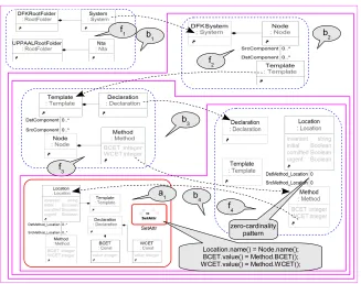
Figure 3: Example PML Block hierarchy
3.3 PML block hierarchy
Mapping blockscan be organized into hierarchy to simplify filter patterns. Figure3illustrates this (filters are named fi, actionsaj and blocksbk):
The topmost filter f1 (in block b1) matches Systems. Sub-block b2’s filter f2 refers to the
Systemmatched using aMatchReferenceobject, and matches allNodeswithin the system, along with their associated Template objects. (SrcComponent →DstComponent associations were created by component skeleton instantiations).
Insideb2, sub-blockb3’s filter (f3) matches the Template’sDeclarationsblock and allMethods
within. f4matches all such Methods with no Location associated by a zero-cardinality pattern, marked in the Figure. Actiona1creates the Location and maps the Method’s BCET and WCET values onto constant declarations within the Template.
Filter conditions in sub-blocks use MatchReferences (dashed frame), which refer to to ele-ments matched by the immediate parent block’s filter. This enables breaking up filter patterns into simpler ones. (Some – not all – MatchReferences are visualized by dashed arrows in Fig.3). Amapping blockhas one filter condition, and zero or more actions.
3.4 Mappings semantics
3.4.1 Global Filter Condition
For each actionai, aGlobal Filter Condition(GFCi) can be constructed by composing associated filter conditions along the block hierarchy:
Definition 1 Global Filter Condition Let fibe the filter of the block containingai. Let fi−1be the filter of the immediate parent block (i.e. one level up in the hierarchy). Comp(fi,fi−1) is a filter obtained by joining fiand fi−1together as follows:
1. theglue graph,Glue(fi,fi−1)is the set of elements of fi−1referenced in fi (dotted frame in the diagrams) along with the associations internal to the set. Start the composition with the glue graph,c0=Glue(fi,fi−1).
2. constructc1=Attach(c0,fi\Glue(fi,fi−1)): add the rest of fiand attach the associations between fiand the glue graph.
3. c2=Attach(c1,fi−1\Glue(fi,fi−1)): add the rest of fi−1and attach the dangling associa-tions betweenc2and the rest of fi−1.
4. Comp(fi,fi−1) =c2.
Then, let us define the composition of filters along the block hierarchy as:
Comp(fi,fi−1, . . . ,f0) =Comp(Comp(Comp(fi,fi−1),fi−2), . . .),f0)
and the global filter condition for actionaias
GFCi=Comp(fi,fi−1, . . . ,f0)
where fi is the filter associated with actionai.
For example,GFC1=Comp(f4,f3,f2,f1) =Comp(Comp(Comp(f4,f3),f2),f1)in Fig.3for actiona1.
3.5 Execution semantics for actions
The execution semantics for actions is shown in Algorithm1:
Algorithm 1Action execution semantics
while ∃isuch that(GFCi)istrue do
Executeactioni
end while
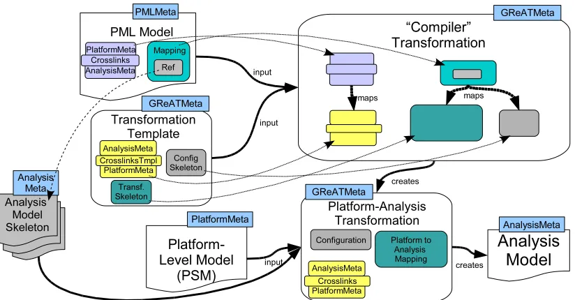
Figure 4: High-level overview of the PML→GReAT transformation
4 Implementing PML over GReAT
GReAT is a general-purpose graph transformation language sharing key concepts with PML, thus implementing PML over GReAT is a straightforward idea. The implementation is done by mapping (translating) a PML specification into an equivalent GReAT transformation — by a “compiler” transformation, specified also in GReAT.
Figure4 provides a high-level overview: Each component in the figure is a model, and the corresponding metamodel’s name is written above the model in a rectangle. The “compiler” takes a PML model (referred asMi in the following discussion) and a GReAT Platform→Analysis transformation template. During compilation, this template is extended with rules generated based onMi.
Mi contains the UML-style metamodels (using an encoding suitable for PML) of the source and target models (platform, analysis), and optional crosslinks. Most importantly, it also contains the
Platform→Analysis mapping definition, with references to external analysis model fragments (skeletons), which are used in Kernel and Component mappings.
The “compiler” GReAT transformation inputsMiand a GReAT template. This template con-tains the appropriate metamodels, and skeletal configuration and transformation specifications (rule-blocks). The “compiler” works by extending these configuration and rule-block skeletons to implement the mapping given inMi.
modeled inMi.
The PML→GReAT “compiler” transformation has the following major phases:
1. Mapping metamodels and crosslinks. Ultimately, the transformation maps PML patterns onto GReAT patterns. Thus, the “compiler” first associates the PML and GReAT meta-models, as bothMiand the GReAT template contain them, in different formats.
2. Extending the template transformation’s configuration such that the appropriate compo-nent skeletons are read and input by the main transformation block, as specified inMi.
3. The template rule blockComponents(on the right side of Fig.4, within block “GReAT Transformation”) is extended to implement the mapping of components captured in the PML model.
4. The template rule blockMappings(block next to isComponents) is extended to im-plement the mappings defined in the PML model.
5 Evaluation
As a case study, we repeated the DSML→Analysis transformation discussed in [SK04]. For DSML the SMOLES language was used, the DFK dataflow package was the implementation platform, and the analysis model was given in UPPAAL (these languages are discussed in [SK04]). This time, with the platform level explicitly present, two transformations were specified (both in GReAT):
1. The SMOLES→DFK implementation mapping (DSML→Platform)
2. The DFK→UPPAAL analysis transformation (Platform→Analysis)
Then, the analysis mapping was also specified using PML. The following table gives a rough complexity comparison of the DFK→UPPAAL mapping in PML and in GReAT. The columns give the counts of GME modeling elements in the models containing the mapping specifications. Both approaches model the “pattern to be matched” (the key concept) almost identically to each other. Thus, the patterns take up approximately the same number of modeling elements. The rest is the overhead required by the language.
Transformation Atoms Models Connections Total
Hand-optimized GReAT 162 43 936 1142 (100%)
PML 77 59 642 778 (68%)
PML compiled into GReAT 567 86 2760 3413 (299%)
influential during the specification of PML. Due to practical considerations, we chose UML over the MOF modeling favored by OMG. Due to its limited scope, PML – unlike ATL – includes no imperative rules, thus it is not ahybridapproach. This makes formal arguments on transforma-tion properties easier.
The idea of using UML model transformations in order to obtain analysis models is demon-strated by the VIATRA [CHM+02] approach. VIATRA does not have the concept ofplatform, thus leveraging on existing DSML→Platform “compiler” implementations is more problematic. With pattern-based languages, expressing thelack of structures is an important question. The AGG [Tae03] approach (and VIATRA as well) uses negative application conditions (NACs). PML useszero-cardinality patterns(with certain limitations) which is a less powerful concept, but so far it seems to be sufficient.
Similar efforts to our platform modeling research were recently published in the middleware community ([SGSS05] and related publications). The authors compose timed automata fragment to model middleware structures. These results are very important as they come from domain experts. They provide generic “recipes” for the formulation and composition of the analysis model fragment. Our research offers a systematic, comprehensive and automated framework.
7 Conclusions
The introduced language, PML keeps and leverages the most useful concepts of general-purpose graph transformation languages (such as GReAT). Such concepts include the UML-inspired vi-sual language and constructing the patterns over metamodel elements, enforcing correctness. At the same time, PML is clean and simple. LHS and RHS are separated, the execution semantics is straightforward, context passing is intuitive.
Using the skeleton concept, key output model elements can be edited in their native modeling environments. This allows analysis experts to focus on the details of the analysis model, instead of trying to map them into complex transformation rules, like the one in Fig.1.
The output is generated as a GME model, conforming to the analysis language metamodel. This model can be exported into various tool-specific concrete syntaxes, such as UPPAAL, HyTech [HHW97] etc.
8 Acknowledgements
The NSF ITR on ”Foundations of Hybrid and Embedded Software Systems” has supported, in part, the activities described in this paper. This material is based upon work supported by the National Science Foundation under Grant No. 0509098
Bibliography
[AD94] R. Alur, D. L. Dill. A theory of timed automata. Theoretical Computer Science
126(2):183–235, 1994.
[BDJ+03] J. B´ezivin, G. Dup´e, F. Jouault, G. Pitette, J. E. Rougui. First experiments with the ATL model transformation language: Transforming XSLT into XQuery. In OOP-SLA 2003 Workshop. Anaheim, California, 2003.
[CHM+02] G. Csert´an, G. Huszerl, I. Majzik, Z. Pap, A. Pataricza, D. Varr´o. VIATRA: Visual automated transformations for formal verification and validation of UML models. 2002.
[Gro03] O. M. Group. OMG / RFP / QVT MOF 2.0 Query / Views / Transformations RFP.
Available from the OMG, 2003.
[GZS+05] A. A. K. G., K. Z., N. S., S. F., V. A. The Design of a Language for Model Trans-formations.Journal of Software and System Modeling, 2005.
[HHW97] T. A. Henzinger, P.-H. Ho, H. Wong-Toi. HYTECH: A Model Checker for Hybrid
Systems.Intl Journal on SW Tools for Technology Transfer1(1–2):110–122, 1997.
[Hol97] G. J. Holzmann. The Model Checker SPIN.IEEE Trans. Softw. Eng.23(5):279–295,
1997.
[KASS03] G. Karsai, A. Agrawal, F. Shi, J. Sprinkle. On the Use of Graph Transformation
in the Formal Specification of Model Interpreters.Journal of Universal Computer Science9(11):1296–1321, 2003. http://www.jucs.org/jucs_9_11/on_
the_use_of.
[LBM+01] A. L´edeczi, A. Bakay, M. Mar´oti, P. V¨olgyesi, G. Nordstrom, J. Sprinkle, G. Karsai. Composing Domain-Specific Design Environments.Computer34(11):44–51, 2001.
18(6):23–33, 2001.
[TS06] D. B. T. Szemethy, G. Karsai. Model Transformations in the Model-Based
Devel-opment of Real-Time Systems. In13th Annual IEEE International Conference and Workshop on the Engineering of Computer Based Systems (ECBS 2006). Potsdam, Germany, March 2006.
[Tae03] G. Taentzer. AGG: A Graph Transformation Environment for Modeling and