JEEECCS, Volume 5, Issue 17, pages 1-10, 2019
An Efficient (Low Resources) Modular
Hardware Implementation of the AES
Algorithm
Paul Burciu
PhD. Electronics Engineering Military Technical Academy
Bucharest, Romania [email protected]
Abstract - The main goal of this paper is to offer a practical modular approach concerning a hardware implementation of the AES cryptographic algorithm, based on a Finite State Machine with Datapath (FSMD) structure. Beyond finding two levels of modularity to be acquired, first referring to AES cryptographic operations over bytes or columns, and the second referring to AES macro-operations, such as cryptographic rounds or key expansion process, this paper provides an optimized solution, in terms of efficient use of FPGA's resources and of speed, to one of our present days' technology challenges, that is, "speed vs. costs". Another goal is to study the consequences, in terms of advantages and disadvantages, of choosing certain design solutions for the hardware implementation on low resources FPGAs.
Keywords-Hardware implementation; crytpo-system; efficiency; modularity; FSMD; block/subblock
I. INTRODUCTION
Modularity is one of today’s key factors concerning either software and hardware implementations. Cryptography does not make exception to this tendency, thus the main objective of this paper being author’s approach regarding a modular hardware implementation of the AES symmetric crypto-system, using a Finite State Machine with Datapath (FSMD) structure. The main idea of this implementation is to modularly integrate every cryptographic operation of AES, such as bytes’ substitution or shifting, column multiplication on Galois Field, or adding round keys, as a first level of modularity, and then, every macro-operation of AES, such as the encryption/decryption round or the key expansion, as a second level of modularity.
Consequently, as a targeted major advantage, this approach aims to provide the developers with the possibility of upgrading modules at both levels, together with efficiency concerning the use of as low FPGA’s platform resources as possible. A pure parallel (pipelined) approach was not possible in this case because this would imply the implementation of all encryption/decryption rounds, thus easily exceeding the available hardware resources. Future works will try to find a solution, if any, for a pipelined
implementation of the same algorithm on a low resources FPGA platform.
From a speed perspective, another targeted advantage is storing keys in RAM, but comparing to an iterative loop solution, this came with the disadvantage of an increased number of necessary clock cycles, the key expansion process being run before the encryption/decryption process. Even though this added 10 more clock cycles before the main process, the speed is not significantly reduced comparing to that of the iterative loop solution.
This paper offers an efficient (low resources) modular hardware implementation of an AES crypto-system ([1]), studying the implication of different design solutions susceptible to be used, pointing advantages and disadvantages of such an approach. It essentially contains 4 chapters, as follows: Chapter I makes an introduction to the topics, Chapter II provides a brief presentation of the theoretical basis, Chapter III details the experimental procedure, and Chapter IV gives conclusions and future topics of research on the field.
II. THEORETICAL ASPECTS
On the first level of modularity, the cryptographic operations are integrated as modules in the mechanism of the appropriate round. In terms of FPGA’s resources, besides being an advantage, this approach might be appreciated as the most economic/efficient because all individual operations are combined and iterated through the algorithm, thus with no possibilities to reduce them. In terms of speed, only a parallel (pipelined) implementation may be more efficient, this being a goal for future studies when dealing with limited resources FPGA platforms (i.e. Xilinx Spartan-6).
module has two components, a one round key expansion submodule which delivers every expanded round key to a RAM submodule, this being the place to store all the round keys and, then, the one to select the appropriate round key to be delivered to the crypto-system. Despite the fact that using RAM might be considered as an advantage, the experimental work proved the opposite because of a small speed loss. The key expansion has also an FSMD structure in order to have the control and data paths synchronized with the main FSMD, that is, the encryption/decryption crypto-system. The advantage of choosing an FSMD structure stands on simplicity of design conception by comparison to an iterative loop structure, that is, more complex to deal with (Fig. 1). In terms of speed, once more, only a parallel (pipelined) implementation may be more efficient, this being subject for future studies.
Figure 1. Iterative loop vs. Pipeline structure [2]
Even if a third level of modularity might exist, referring to basic operations like column multiplications on Galois Field by some binary hex coded values (i.e. x“02”, x“03”, x“09”, x“0B”, x“0D”, x“0E”), this paper will not treat it because, in terms of speed and resource consumption, there are more efficient methods to implement it. One such method, which may be another advantage to be pointed on this paper, is calling each of the multiplication operations as functions from the VHDL package, combined with the decomposition into combined multiplications by x“02” and x“03” of every multiplication by numbers bigger than x“03” (i.e. x“09”, x“0B”, x“0D”, or x“0E”) ([2]). By comparison to accessing operations through VHDL components, accessing functions from VHDL package is generally faster, in terms of throughput, this being calculated by (1) ([2]), but often efficient, in terms of consumed resources, as proved by some of previous author’s experiments with their results shown by TABLE I and TABLE II (Chapter III).
(1)
III. EXPERIMENTAL WORK
All implementations and simulations were done by using Xilinx ISE Design Suite (shareware version 14.7) ([3]), on a Xilinx Spartan-6 platform (Fig. 2), a low resources FPGA device, as well as, for comparison, on a Xilinx Virtex-5 platform (Fig. 3), a well-equipped FPGA device.
From TABLE I and TABLE II it may be found that all the presented implementations have low percentages of resources consumed from the available that were summarized by TABLE III.
Figure 2. Xilinx Spartan-6 FPGA platform [4]
Figure 3. Xilinx Virtex-5 FPGA platform [4]
TABLE I. THROUGHPUT [GBPS] AND CONSUMED RESOURCES] COMPARISON (XILINX SPARTAN-6) VHDL Pack. Function Enc. VHDL Comp. Enc. VHDL Pack. Function Dec.V1 VHDL Comp. Dec.V1 VHDL Pack. Function Dec.V2 VHDL Comp. Dec.V2
2.347 2.023 1.706 1,862 1.540 1.885
6% 6% 7% 7% 6% 7%
TABLE II. THROUGHPUT [GBPS] AND CONSUMED RESOURCES] COMPARISON (XILINX VIRTEX-5) VHDL Pack. Function Enc. VHDL Comp. Enc. VHDL Pack. Function Dec.V1 VHDL Comp. Dec.V1 VHDL Pack. Function Dec.V2 VHDL Comp. Dec.V2
3.660 3.660 2,587 2,420 2,715 2,436
4% 5% 5% 6% 5% 5%
TABLE III. COMPARISON BETWEEN AVAILABLE RESOURCES OF XILINX SPARTAN-6 AND VIRTEX-5 FPGA DEVICES [4]
Spartan-6 Virtex-5
Logic Cells 3,840 147,443 19,968 331,776
LUTs 2,400 92,152 19,200 207,360
Flip Flops 4,800 184,304 19,200 207,360
Distributed RAM(KB) 75 1,355 210 4,200
DSP48 Slices 8 180 24 1,056
BRAM(Kb) 216 4,824 936 18,576
CMTs 2 6 1 6
Maximum GTP
Transceivers 0 8 0 24
Total I/O Banks 4 6 7 33
Max User I/O 132 576 172 1,200
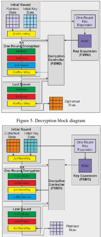
last round, which are different from the others (the first round only includes the AddRoundKey transformation applied to the plaintext/ciphertext and the initial key, while the last round only includes 3 of the 4 transformations, that is, SubBytes/ InvSubBytes, ShiftRows/InvShiftRows, and AddRoundKey, with the MixColumns/InvMixColumns transformation missing), together with only a complete one round (including all 4 round transformations) out of the 9 AES-128 encryption/decryption rounds, which is 9 times run in an iterative loop by the FSMD controller (Fig. 4, 5).
Figure 4. Encryption block diagram
Figure 5. Decryption block diagram
The above figures are clearly expressing a modular architecture of the AES-128 implementation, which is organized on 2 levels of modularity, as follows:
On the first level, we have all 4 transformations included as subblocks of an AES-128 round, together with one round key expansion and RAM, as subblocks of the key expansion process.
On the second level, we have 3 different types of AES-128 round blocks, as well as the key expansion block.
This modular hardware structure gives developers the advantage of upgrading modules at both levels, as well as efficiency of resource consumption.
The programming solution is an optimized combination between VHDL architectural entities, instantiations, and a package, while the hardware functional blocks are described behaviorally by fragments of programs/subprograms which will be finally assembled into programs/subprograms.
In order to minimize used hardware resources on a complete round, the sequence of transformations is:
SubBytes, ShiftRows, MixColumns, and AddRoundKey, for AES-128 encryption;
InvSubBytes, InvShiftRows, AddRoundKey, and InvMixColumns, for AES-128 decryption.
In case of decryption algorithm, the same objective may be achieved by applying the algebraic distributive law ([2]), concerning multiplication on Galois Field (denoted as ) and XOR (denoted as ) operations, thus making InvMixColumns and AddRoundKey transformations interchangeable (2). The advantage of choosing this solution, both in terms of speed and consumed resources, may be proved by author’s previous experiments (TABLE IV and TABLE V).
Y
Z
X
Y
X
Z
X
(2)where
X
,
Y
,
Z
GF
2
8 .TABLE IV. THROUGHPUT [GBPS] AND CONSUMED RESOURCES COMPARISON (XILINX SPARTAN-6)
Dec.V1 Without DistribLaw
Dec.V2 With DistribLaw
Dec.V1 Without DistribLaw
Dec.V2 With DistribLaw
1.706 1.540 1,862 1.885
7% 6% 7% 7%
TABLE V. THROUGHPUT [GBPS] AND CONSUMED RESOURCES COMPARISON (XILINX VIRTEX-5)
Dec.V1 Without DistribLaw
Dec.V2 With DistribLaw
Dec.V1 Without DistribLaw
Dec.V2 With DistribLaw
2,587 2,715 2,420 2,436
5% 5% 6% 5%
The design of AES-128 hardware implementation essentially consists of establishing the main encryption/decryption control signals together with those to be applied to, that is, data signals, resulting in a main signals diagram (Fig. 6) which will be further completed by regular signals.
This diagram shows synchronization between the system clock and all the signals that are implied in loading the plaintext/ciphertext and the initial key, in beginning and ending of encryption/decryption process, or in forming the output message, that is, the ciphertext/plaintext, but not with the RESET signal which is asynchronous. The activation of all these signals was done by the rising edge of the system clock. PROC_ACK signal confirms the possibility of processing data to the controller. Activation of this signal is mandatory in order to begin the key expansion, by using the BEGIN_KEXP signal, and to run it for 10 clock cycles. After the key expansion ending, PROC_ACK is again activated in order to confirm the possibility of beginning the encryption/decryption process. After the plaintext/ciphertext (denoted as PTXT_INP/ CTXT_INP) and the initial key (denoted as KEY_INP) were loaded through a LOAD signal, and after the encryption/decryption beginning signal (denoted as BEGIN_ENC/ BEGIN_DEC) was activated, it takes 10 clock cycles for this process to be fulfilled, until the END_ENC/ END_DEC signal is activated and the output (denoted as CTXT_OUT/ PTXT_OUT) is obtained.
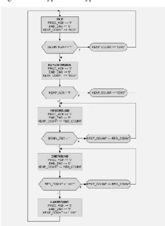
The FSMD structured block will be described by an ASMD chart (Algorithmic State Machine with Datapath) which will serve as a basis for the VHDL program of the implementation (Fig. 7).
Figure 7. Encryption/Decryption controller ASMD
The ASMD chart contains a minimum of 5 FSMD states, namely:
IDLE is the initial state, when PROC_ACK is activated in order to acknowledge the possibility of beginning the key expansion process, if and only if the specific signal, that is, BEGIN_KEXP is activated; the encryption/decryption ending signal (i.e. END_ENC/END_DEC) is deactivated and the round counter, denoted as KEXP_COUNT, is
set to a binary value of "0000" (i.e. decimal value of 0); activation of BEGIN_KEXP means transition to the next state, namely KEYEXPANSION, while deactivation of it keeps KEXP_COUNT on the initial position of "0000".
KEYEXPANSION is meant for the key expansion process, when PROC_ACK and END_ENC signals are deactivated, and the round counter has still a value of "0000"; the activation of KEXP_ACK means transition to the next state, that is, FIRSTROUND, while deactivation of it means the round counter remains "0000".
FIRSTROUND is the first encryption/decryption round, when PROC_ACK is again activated in order to acknowledge the possibility of beginning the encryption/decryption process, while END_ENC is disabled and the round counter is stored on the counter register, denoted as REG_COUNT; activation of the encryption/decryption beginning signal (i.e. BEGIN_ENC) means transition to the next state, that is, ONEROUND, while deactivation of it means the round counter takes its value from the counter register.
ONEROUND means a complete encryption/decryption round, when PROC_ACK is deactivated, as well as the encryption/decryption ending signal, while the round counter still takes its value from the counter register; if the counter register has achieved a binary value of "1010" (i.e. decimal value of 10), we have a transition to the next state, that is, LASTROUND, but if not, the round counter takes its next value from the counter register.
LASTROUND is the final encryption/decryption round, when PROC_ACK is still deactivated, the encryption/decryption ending signal is activated and the round counter’s value is 10.
This sequence of states is setting out 4 hardware blocks/modules of encryption/decryption (Fig. 4, 5), as follows:
The key expansion block;
The first round block;
The one round block;
The last round block.
Figure 8. Main signals diagram of key expansion (similar to the decryption version)
The main signals diagram of key expansion shows synchronization between the system clock and all the signals that are implied in loading the key, in beginning and ending of the key expansion, or in forming the output message, that is, the round key, the activation of all these signals being done by the rising edge of the system clock. Key expansion main signals were, as follows: KEXP_INP, the initial key which is introduced while the initiation of key expansion, COUNT, that is, the counter of encryption/decryption rounds, BEGIN_KEXP, which is responsible for key expansion’s beginning, END_KEXP, being the signal to activate the end of key expansion process after 10 clock cycles from its start, and finally, KEXP_OUT, that is, the output round key.
A disadvantage of this implementation is that key expansion is run before encryption/decryption, thus adding 10 more clock cycles to the main process, but offering the advantage of storing keys in RAM, while speed and resource consumption still have reasonable values (Appendix A), by comparison to the iterative loop with VHDL components, which runs for 11 clock cycles. The explanation is that the FSMD structure used Block RAM/FIFO resources to increase speed. Hence, if these processes were simultaneous, the FSMD throughput would be double, thus bringing it close to previous implementation. Therefore, a goal of the future work will be making encryption/decryption and key expansion simultaneous.
Another advantage of the FSMD structure is that it used significantly less bonded IOBs than the other. As expected, the number of used Slice Registers is higher than the iterative loop case and this is a result of pipeline characteristics of the FSMD architecture.
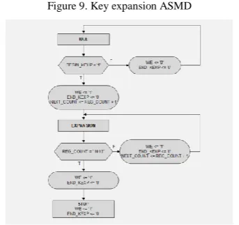
The FSMD structured subblock of key expansion was described by an ASMD chart, which serves as a basis for the VHDL program (Fig. 9).
Figure 9. Key expansion ASMD
The ASMD chart contains a minimum of 3 states, as follows:
IDLE is the initial state, when as the key expansion was started by BEGIN_KEXP and writing in RAM was activated by WE signal, the ending of key expansion is deactivated through END_KEXP, and the expansion round counter is incremented by 1; activation of BEGIN_KEXP means transition to the next state, that is, EXPANSION, while deactivation of BEGIN_KEXP means deactivation of both writing in RAM and ending of key expansion process.
EXPANSION is meant for running the key expansion process, when as long as the counter register achieved a binary value of "1010" (i.e. decimal value of 10), WE is kept activated, END_KEXP is still deactivated, and the next state is STOP; if the counter register did not achieve "1010", it is incremented by 1.
STOP is the final key expansion state, when writing in RAM is activated by WE signal and, also, the ending of key expansion is done by the activation of END_KEXP signal.
As the number of states increases, then, the number of used FPGA platform resources will consequently increase. For this reason, by means of number of states, several versions of FSMD controllers, both for encryption/decryption and for key expansion, were tested by the author in order to find out this minimal solution.
The key expansion (i.e. FSMD controller) subblock, defined itself as an instance of the encryption/decryption main block, has 2 instantiated subblocks, that is, the one round key expansion and the RAM subblocks.
Concerning the implementations of encryption and decryption, there is a difference between them, this providing decryption with a better throughput (Appendix A): besides the particular round constant RCON [1], contained by the FSMD controller, there is a reduced signal structure of the decryption one round key expansion subblock, by comparison to the encryption correspondent.
Each of the expanded round keys will be stored in RAM and provided as needed to the appropriate round by selecting it with a RAM ADDRESS signal which has a binary value that is equal to the binary equivalent of the round number.
The VHDL implementation solution for the RAM subblock was mainly inspired by a standard solution offered to users by Xilinx ISE programming platform ([3]), through “Synthesis Constructs” portfolio, and then, adapted by the author according to [5], to the encryption/decryption key expansion block.
blocks were integrated as VHDL instances of the encryption/decryption controller block.
The first round block was defined as for the initial encryption/decryption round, which only contains an AddRoundKey transformation that was applied to the plaintext/ciphertext message and to the initial key. The VHDL architectural body of its implementation consists of a single subblock instantiation statement, meaning of the AddRoundKey transformation (Appendix C). The output signal of the first round block is provided to the FSMD encryption/decryption controller block and connected to the input of the next round block (Appendix C).
The one round block integrated all 4 round transformations of AES-128 crypto-system as VHDL instances, as previously mentioned on this chapter. Also, it is integrated as an instance by the encryption/decryption controller block which will iterate it 9 times, that is, for 9 out of 10 AES-128 rounds (Appendix D). The VHDL architectural body of its implementation consists of 4 subblock instantiation statements, so that each instantiated subblock’s output is connected to the input of the next instantiated subblock, except of the output of the last subblock which is provided to the FSMD encryption/decryption controller block and connected to the input of the next round block (Appendix D). Each of the 4 transformations was implemented according to [1] as a separate VHDL program.
The last round block integrated 3 out of 4 round transformations of AES-128 crypto-system as VHDL instances (i.e. except MixColumns). This block is then integrated by the encryption/decryption controller block (Appendix E). The VHDL architectural body of its implementation consists of 3 subblock instantiation statements, so that each instantiated subblock’s output is connected to the input of the next instantiated subblock, except of the output of the last subblock which is provided to the FSMD encryption/decryption controller block and connected to the output of the crypto-system (Appendix E).
Another optimization brought by this implementation, in terms of speed of operation, was calling of an integer table constant (denoted as SBOX) from the VHDL package instead of a long sequence of CASE statements, when running a SubBytes transformation of the one round key subblock. In order to have a minimized VHDL package, so that to reduce the consumed resources, it only integrated 2 substitution tables (provided by [1]), that is, for SubBytes and InvSubBytes transformations, and 2 multiplication functions that were designated for MixColumns and InvMixColumns transformations.
For comparison, Appendix G ([6]) gives, together with author’s current implementations, examples of recent AES FPGA implementations from literature, mainly using low resources FPGA devices.
The functional verification of the implementation was made by using the simulation process which was facilitated by Xilinx ISE programming software (Appendix F). This was done by running the specific testbench, that is, the testing software module which
contains the hardware implementation to be tested (i.e. the encryption and the decryption module).
Finally, the potential applications that might integrate an FPGA cryptographic implementation (i.e. distance learning, multiple digital TV, video streaming or telemedicine) demand up to 24 Mbps of speed, according to TABLE VI ([2]), but other recent applications (i.e. Bluetooth 5.0 or 4K video streaming) may need up to 25 Mbps, all these requirements being satisfied by this implementation. In the meantime, modern cloud computing may need a bandwidth of up to 10Gbps, thus requiring from cryptographic implementations a serious speed improvement.
TABLE VI. POTENTIAL CRYPTOGRAPHIC APPLICATIONS [2]
Application Upstream Downstream
Distance learning 384Kbps-l.5Mbps 384Kbps-l.5Mbps
Telecommuting 1.5Mbps-3.0Mbps 1.5Mbps-3Mbps
Multiple digital TV 6.0Mbps-24.0Mbps 64Kbps-640Kbps Internet Access 400Kbps-1.4Mbps 128Kbps-640Kbps
Web hosting 400Kbps-1.5Mbps 400Kbps-1.5Mbps
Video conferencing 384Kbps-1.5Mbps 384Kbps-l.5Mbps
Video on demand 6.0Mbps-18Mbps 64Kbps-128Kbps
Interactive video 1.5Mbps-6.0Mbps 128Kbps-1.5Mbps
Telemedicine 6.0Mbps 384Kbps-1.5Mbps
High-definition TV 16Mbps 64Kbps
IV. CONCLUSIONS
This paper presented a modular hardware implementation of AES crypto-system and studied implications of different design solutions susceptible to be used. This implementation provides the developers with the possibility of upgrading modules at both levels of modularity and of efficiently using resources from a low equipped FPGA platform. Additionally, it provides the option of storing keys in RAM, causing a supplementary number of clock cycles, but not significantly affecting the system speed.
Future research will try to find any possible solution for a pipelined implementation of the AES algorithm on low resources FPGA platforms, with simultaneous encryption/decryption and key expansion, in order to achieve high encryption/decryption speed, as demanded by current communication applications.
REFERENCES
[1] FIPS, PUB 197, “Announcing the Advanced Encryption Standard (AES)”, U.S.A., 2001.
[2] Francisco Rodriguez-Henriquez, N.A. Saqib, A. Diaz-Perez, Cetin Kaya Koc, “Cryptographic Algorithms on Reconfigurable Hardware”, Springer Science+Business Media LLC, New York, U.S.A., 2006.
[3] Xilinx ISE 14.7 programming platform (shareware version) [4] https://www.xilinx.com/support/documentation/data_sheets [5] Pong P. Chu, “FPGA prototyping by VHDL examples”, John
Wiley & Sons, Inc., Hoboken, New Jersey, U.S.A., 2008. [6] K. Rahimunnisa, P. Karthigaikumar, Soumiya Rasheed, J.
APPENDIX A-IMPLEMENTATION PARAMETERS OF FSMD VS ITERARTIVE LOOP [3]
FSMD - Encryption
FSMD - Decryption
Iterative Loop - Encryption
Iterative Loop - Decryption
Throughput [Gbps] 0.911 0.952 2.023 1.885
Percentage of occupied area 9% 10% 6% 7%
Maximum Frequency [MHz] 167.193 148.687 173.882 161.979
Minimum period [ns] 5.981 6.726 5.751 6.174
Minimum input arrival time before
clock [ns] 5.699 6.059 5.048 4.452
Maximum output required time after
clock [ns] 7.146 7.180 4.162 3.634
Slice Logic Utilization
Number of Slice Registers 1,606/
5,4576 2%
1,607/
54,576 2%
793/
54,576 1%
789/
54,576 1%
Number of Slice LUTs 4,450/
27,288 16%
4,719/
27,288 17%
1,786/
27,288 6%
2,155/
27,288 7%
Number used as Logic 4,450/
27,288 16%
4,719/
27,288 17%
1,786/
27,288 6%
2,155/
27,288 7%
Slice Logic Distribution
Number of LUT Flip Flop pairs used 4,761 4,940 2,049 2,395
Number with an unused Flip Flop 3,155/
4,761 66%
3,333/
4,940 67%
1,256/
1,916 61%
1,606/
2,395 67%
Number with an unused LUT 4,761 311/ 6% 4,940 221/ 4% 1,916 263/ 12% 2,395 240/ 10%
Number of fully used LUT-FF pairs 1,295/
4,761 27%
1,386/
4,940 28%
530/
1,916 25%
549/
2,395 22%
Number of unique control sets 32 30 6 6
IO Utilization
Number of IOs 6 6 261 261
Number of bonded IOBs 6/
296 2%
6/
296 2%
261/
296 88%
261/
296 88%
Specific Feature Utilization
Number of Block RAM/FIFO 4/
116 3%
4/
116 3% - - - -
Number using Block RAM only 4 4 - - - -
Number of BUFG/BUFGCTRLs 1/
16 6%
1/
16 6%
1/
16 6%
1/
16 6%
APPENDIX B-ENCRYPTION BLOCK DIAGRAM (SIMILAR TO THE DECRYPTION VERSION)[3]
APPENDIX D-ONE ROUND ENCRYPTION SUBBLOCK (SIMILAR TO THE DECRYPTION VERSION)[3]
APPENDIX E-LAST ROUND ENCRYPTION SUBBLOCK (SIMILAR TO THE DECRYPTION VERSION)[3]
APPENDIX F-THE ENCRYPTION SIMULATION (SIMILAR TO DECRYPTION)[3]
APPENDIX G-COMPARISON OF PROPOSED DESIGN WITH EXISTING ARCHITECTURES [6]
Author Architecture FPGA device Throughput (Gb/s) Frequency
(MHz) Slices/available
ENC ENC/DEC
This work State machine-based
AES Spartan-6 0.911 0.952 142.356 2090/27288
This work Sequential Spartan-6 2.023 1.885 173.882 1786/27288
K. Rahimunnisa et
al. [6] Basic AES Virtex-6 XC6VLX75T 11 16 505.5 2053/93120
K. Rahimunnisa et
al. [6] Folded structure Virtex-6 XC6VLX75T NA 25.32 505.5 1586/93120
K. Rahimunnisa et
al. [6] Folded with parallel Virtex-6 XC6VLX75T 32 37.1 505.5 1664/93120
Granado-Criado et al. [4]
Partial and dynamic
reconfiguration XC2V6000-6 24.922 NA NA 3576/33792
Alaoui Ismaili et al. [6]
Self-partial and dynamic
reconfiguration Spartan II–XC2s200E 0.016 NA 28.7 196/2353
Rais et al. [22] Simple AES Virtex-5 XC5VLX50 4.34 NA 339.09 399/7200
Fan et al. [10] Fully pipelined XC2V3000-6 NA 28.4 222.2 139357/14334
Virtex-4 2.9 250 700/1220
Spartan-3 1.7 150 1800/2150
Lemsitzer et al. [24] GCM AES Virtex-4 NA 17.9 140 18400/1220
Yoo et al. [11] Interpipelining and
intrapipelining XC2VP70-7 29.77 NA 125.3 200/5177
Good et al. [25] LUT-based AES Virtex-E XCV2000E-8 NA 23.65 184.8 16693/19200
Spartan-III XC3s2000-5 NA 25.10 196.1 17425/1280
Kotturi et al. [26] Parallel pipelined AES XC2VP70-7 29.77 NA 232.6 5408/5177
Aziz et al. [27] CCM Spartan
II-XC3s200pq208-5 2.699 NA 231.97 481/120
Rouvroy et al. [7] AES for embedded Virtex-2 NA 0.358 123 146/256
Hodjat et al. [9] Fully pipelined XC2VP20-7 21.54 NA 157 5177/5177
Zhang et al. [12] Subpipelining XCV1000-8 21.57 NA 168.4 11022/1536
Zambreno et al. [28] AES Virtex-II XC2V4000 23.57 NA 184.1 16938/17021
Farhan et al. [29] Simple AES Xilinx x2v1000 1.45 NA 119 542/5120
Hodjat et al. [30] Fully pipelined XC2VP20-7 21.64 NA 169.1 9445/5177
Sever et al. [31] Sequential XC2V8000-5 NA 0.83 65 8378/46592
Wang et al. [32] Sequential XCV1000e-8 NA 0.463 75 5150/1536
Standaert et al. [8] Pipelined XCV3200e-8 18.5 NA 169 2257/8235
Chodowiec et al. [3] Folded Spartan II-XC2S30 NA 1.3 50 222/54
Jarvinen et al. [33] Fully pipelined Virtex-E XCV1000e-8 16.5 NA 129.2 11719/1536
Saggesse et al. [34] Unrolling, tiling, and
pipelining Virtex-E XCV2000e-8 20.3 NA 158 5810/19200
Vu et al. [35] CCM Spartan II-2s200pq208-5 NA NA 43.34 2035/120
Saqip et al. [36] Sequential XCV812 0.259 NA 22.41 2744/8544
Standaert et al. [37] Reconfigurable AES Virtex-5 NA 1.45 119 542/4800
Chittu et al. [14] State machine-based
AES Virtex-II XC2V1000-4 NA 0.739 75 4325/5120
Sklavos et al. [17] Sequential XCV300BG432 NA 0.259 22 2358/384
Chitu et al. [38] Sequential XC2V1000-1 NA 0.739 75 4325/5120
Helion [39] AES Virtex-5 NA 4.1 350 349/4800
Manavski [40] AES NVIDIA
GeForce8800GTXGPU 8.28 NA NA NA
Harrison et al. [41] AES GeForce7900GTGPU NVIDIA 0.87 NA NA NA
![Figure 1. Iterative loop vs. Pipeline structure [2]](https://thumb-us.123doks.com/thumbv2/123dok_us/7805586.2085007/2.595.81.250.261.357/figure-iterative-loop-vs-pipeline-structure.webp)