Journal of Electrical Engineering,
Electronics, Control and Computer Science –
JEEECCS, Volume 4, Issue 12, pages 19-26, 2018
Relative Permittivity Based Model for GSM
Signal Loss in Buildings
Promise Elechi
Department of Electrical Engineering Rivers State University
Port Harcourt, Nigeria
Fredrick O. Edeko and Joel O. Egwaile Department of Electrical/Electronic Engineering
University of Benin Benin City, Nigeria.
Abstract – In this work, measurements of GSM signal strength were conducted in buildings to determine the signal penetration loss through them. This was carried out using Radio Frequency Signal Tracker installed in Tecno N9 tablet. These buildings were made with different materials such as Mud, sandcrete, and alucoboard. The average penetration loss was computed by subtracting the indoor received signal strength from the outdoor received signal strength, the same for both closed and opened doors and windows and the in-building (obstructed) penetration path loss exponent was determined. Based on the measurement data, a path loss model was developed using Snell’s law and by considering the free space loss, log-normal loss, the deduced in-building path loss exponent, and the distance between the transmitter and receiver. The developed path loss model was compared with the ITU-R indoor path loss model and a Matlab based user interface for instant path loss prediction was also created. The measurement results indicated that the building with alucoboard wall cladding had the maximum signal penetration loss (104.52 dB) while the sandcrete building with unrusted corrugated iron sheet roof had the minimum signal penetration loss (81.85 dB). The results also showed that the in-building path loss exponent as the signal passed from outdoor to indoor through the building material were from 0.87 to 1.32. The path loss exponent from the transmitter to the receiver varied between 4.87 to 5.32, and the standard deviation between 17.0dB to 17.8dB. The comparison of the developed model to the ITU indoor path loss model showed very close relationship. This work has deduced a path loss exponent for GSM signal penetration in buildings which is dependent on the building material for the first time in Nigeria.
Keywords- Building, Path Loss, Model, GSM, Signal, Penetration.
I. INTRODUCTION A. Background of the Study
Communication is an important area of science that has always been a focal point for transferring information among parties at locations physically apart [1]-[5], [23]. Wireless communications systems are also a basic need in modern society. Available Statistics have shown that in many parts of the world, there is an increase in the use of mobile phone than the fixed one [23], [20]-[21], [7]-[9]. Mobile phones are used everywhere, both outdoor and indoor. In our modern environments, GSM subscribers demand good signal coverage and quality of service (QoS). The
increased demand for personal communications network has led to the understanding that not much is known about radio wave propagation either into or within buildings. Signal propagation models that can adequately describe it in open and urban areas are not enough to determine the amount of signal degradation, since there may exist penetration loss associated with the indoor environment [1]-[4], [14].
Nigeria‟s telecommunication network has improved and become available to the average individuals in the country [11]. However, GSM has its own challenges such signal level fluctuations during call services especially when indoor. This is because when GSM signals pass through a medium that is obstructing the transmission of electromagnetic wave; it experiences a loss commonly referred to as penetration loss [3], [20]. According to [7]-[10], building penetration loss, has certain amount of impact on the quality of the signals received inside a building due to an external transmitting signal loss (outdoor-to-indoor reception). Penetration loss accounts to certain percentage of the total loss of a communication link [6]-[8], though the actual percentage is not yet known. In this research work, the actual percentage of the building penetration loss will be determined. Another source of poor radio signal performance can be signal absorption by building materials which also accounts for signal attenuation. Modern construction methods and materials for large commercial buildings have been attributed to be the source of poor radio performance [15], [24].
B. Review of GSM Signal Penetration Loss in Buildings
Research on signal loss in buildings was first carried out by Rice, in 1959 [3]-[6], [5] [15] [14] which he called “Local Building Losses”. Since then, there have been many studies on GSM signal losses due to building pattern, each of these studies adopted different approaches but none has given adequate attention to the percentage of loss associated with the building materials and how they affect the signal quality.
[12] conducted measurement of data for 2.5 & 60GHz in-building partition loss. Path loss measurements were conducted in 22 locations in an office using a broadband sliding correlator channel sounder. The transmitters and receivers were separated at a range of 3.5 to 27.4 meters and were separated by a variety of obstructions, in order to emulate future single-cell-per-room wireless networks. Their measurements may have aided in the development of future in-building wireless networks in the unlicensed 2.4GHz and 60GHz bands but their study did not consider the effect of building pattern to the signals.
[25] monitored signal strength variation in terms of shadow or multi path fading using Log normal and Rayleigh distribution. Measurements were conducted in the football pitch of Adamawa State University, Mubi for two weeks and a total of 700 observations were made Glo and Zain networks. Their investigations showed the attenuation of GSM signal strength in the chosen location as a result of the signal fading. The results showed that the network‟s signal strength received at Adamawa State University was not too adequate but insufficient enough to offer the customer‟s demand for good quality of service. Their results showed less on the impact of building loss as well as penetration loss.
[18] conducted a study of GSM signal attenuation due to building and its associated path loss from the Base transceiver Stations to the Mobile equipment on different buildings for GSM (900 and 1800 MHz) and UMTS. In their study, a statistical model the penetration loss was developed using Log-Normal Distribution. The rate of signal attenuation variation per floor, and rooms were analysed. The results showed a mean signal loss of 5.7 dB for GSM900 with a standard deviation of 11.1dB. There results did not show the impact of the building walls even though there was a model to predict signal attenuation.
[14] investigated path loss characterization over a wide range of frequency 300MHz – 3GHz, in an industrial environments. The results showed the impact of frequency variation on the signal quality in the environment. It was shown that there are regions in the spectrum where the path loss dips with respect to certain frequencies and that those dips were modelled using a simple two-beam propagation model normally used for outdoor propagation over infinite fields. The overall conclusion was that industrial environments were heterogeneous in propagation characteristics than most were commonly assumed.
[20] conducted measurements to show the amount of loss in GSM signals in some buildings. According
to the authors, this could be attributed to the building penetration loss, which may be responsible for the increased level of attenuation of the received GSM signal level when a mobile device is moved indoor from outdoor. Their measurements showed that signal degradation increased with increasing penetration loss which depended on the type of building material. The work involved measurements of two GSM Operators in Nigeria, their signal levels were measured for both outdoor and indoor on two selected buildings made with concrete and block. A Samsung Galaxy GT-35000 mobile phone with Radio Frequency signal tracker software installed in it was used and the results showed a mean loss of 10.62dB, and 4.25dB for the concrete and block buildings respectively.
All the review works showed that building losses exist in wireless communication. Some considered a particular frequency of transmission which are either higher or lower than the frequency for GSM communication, although there were also many studies on GSM signal building loss. All these studies have tried to consider buildings as obstacles to signal penetration but have not shown how building materials affect GSM signal quality or the amount of loss, rather they have only established that buildings can cause signal loss. Also, they did not show the loss in storey buildings. Therefore, this work will determine the amount of GSM signal loss in buildings due to the materials used in the construction of the building. In this work, the relative permittivity of the building material and distance from transmitter are assumed to be responsible for the poor signal quality experienced in buildings, the details of their effects will be made clearer in this work as being responsible for the penetration loss and free-space loss.
C. GSM Signal Propagation Mechanisms
Radio waves propagating in an indoor environment can be subjected to some mechanisms such as signal reflections, diffractions and scattering [12], [6]-[8], [3], [20]. Reflection is said to have occurred when an electromagnetic wave hits the surface of an object with much larger dimensions than its wavelength and bounces off through a different path [16].
Diffraction is said to occur when an objects is placed in the line-of-sight of an electromagnetic wave signal pathway. If the object has sharp edges and is not large enough to shadow the signal completely, this results to the bending of radio waves around the corners of the obstructing object which can be seen as a secondary transmitter [23]. Scattering is said to occur when the propagating wave strikes a rough surface where the dimensions of the irregularities are of the wavelength size or smaller [5]-[7]. In signal analysis, first the free space path loss, FSPL, is derived and then various path loss models can be discussed.
D. Path Loss
diffraction, refraction, free space loss, aperture-medium coupling loss, and absorption. It is also influenced by terrain contours, environment such as rural, urban, vegetation and foliage; propagation medium such as moist or dry air; the distance between the transmitter and the receiver, and the height and location of antennas. The causes of path loss includes propagation losses caused by the natural expansion of the radio wave front in free space, absorption losses (sometimes called penetration losses). It is usually expressed in dB. There are many empirical outdoor propagation path loss models such as Okumura model, Hata model, COST 231, etc, and indoor propagation models such as ITU-R model, etc [2]-[5], [17]-[18].
II. MATERIALSANDMETHOD
A. Methodology
In this section, GSM signal strength measurements were conducted on six buildings made with different building materials and storey buildings, each in four (4) different locations (6 buildings in each of the locations considered. The study was carried out using the base transceiver stations of the four GSM service providers (MTN, Etisalat (9mobile), Glo and Airtel) in Nigeria, to determine the signal penetration loss through the buildings made with different materials using Radio Frequency Signal Tracker (RFST) software. The Radio frequency Signal Tracker installed in Tecno N9 was used in carrying out the measurements to determine their signal-to-noise ratio (SNR), signal strength, and their respective distances from the measurement site to the Base Transceiver Stations (BTS).
The measurements in each of the four different locations were conducted on:
1. Mud building/thatched roof (MBTR),
2. Mud building/rusted corrugated iron sheet roof (MBCR),
3. Sandcrete building/unrusted corrugated iron sheet roof/PVC ceiling (SBUR),
4. Sandcrete building/rusted corrugated iron sheet roof (SBCR),
5. Sandcrete building/unrusted corrugated iron sheet roof/POP ceiling (SBPC),
6. Building with Alucoboard wall cladding (BAWC).
B. Measurements and Data Presentation Measurement Procedures
In all the buildings considered, measurements were carried out daily for 30 days in each month. This is to obtain more accurate data. In each location, measurement were first conducted outside the building in the direction of the BTS and then inside the building also in the direction of BTS. The same was also carried out in all the partitions of the buildings considered, this is to determine their partition loss. The monthly average received signal strength was determined by dividing each monthly measured data
by 60 (total number of measurements in a month) as illustrated in equation (1).
(1)
where RSSAV is the average received signal strength
and x represents each of the measured data in a month. Also, for each of the measurements, the wall penetration loss was computed as [5], [21]:
(2) where Apen-loss is the average penetration loss in dB,
Sin is the average signal strength inside the building in
dBm and Sout is the average signal strength outside the
building in dBm. The measurements inside the building were conducted in all the rooms in each of the buildings so as to determine the partition losses. According to [16], and other researchers windows especially glass have less effect on signal quality [6], [16], and [15]. In all the measurement locations, the distance from the base transceiver station (BTS) to the test site were first measured.
C. Computation of In-building Path Loss Exponent The in-building (obstructed) path loss exponent represented as , is equal to:
(a) The in-building penetration path loss exponent based on the building material ( ) (b) The outdoor path loss exponent (n) was
computed as:
(3)
(4)
(5)
(6)
Therefore,
(7) In the computation of the in-building obstructed penetration path loss exponent, the outdoor path loss and its exponent were considered. According to [6], the average received signal strength at any point in a mobile radio channel is:
( (8)
where is the received power in dBm, is the transmit power in dBm, K is the square of the average penetration loss, d is the distance between the transmitter and receiver, is the reference distance, and is the in-building path loss exponent.
Expressing equation (8) in logarithmic form gives:
(9)
(10)
(for indoor) and for GSM 900 (MTN, Glo, Etisalat and Airtel vendor document, 2016). From equation (6), the computed outdoor path loss exponent is 4. This is the path loss exponent for shadowed urban environment [16]. Table 1 shows the deduced signal penetration path loss exponent.
TABLE 1: Deduced In-Building Path Loss Exponent based on Building Material
Building Material
MBT R
MBCR SBCR SBUR SBPC BAW
C In-Building
Exponent
( )
1.32 1.16 1.11 0.87 1.30 1.32
D. Computation of Outdoor Path Loss
To compute the outdoor path loss, equation (11) was be applied
(11) but
(12)
Where is the wavelength, is the speed of light and is the frequency;
Using an operating frequency of 900 MHz for all the networks, (this is because measurements were carried out on GSM-900 only), therefore
For a reference distance of 100 m from the BTS, (for outdoor)
(13)
Hence, for a distance of 1 km, the path loss per meter with respect to this distance will be:
This implies that the free space loss rate over a distance of 1 km is 0.0716 dB per meter.
The outdoor path loss will be:
E. Computation of Path Loss for the Buildings The computation of the indoor building penetration loss was based on the measured data from each of the buildings considered (MBTR, MBCR, SBCR, SBUR, SBPC, and BAWC). Therefore, the total indoor signal penetration path loss in the buildings will include both the outdoor loss and the building material penetration loss.
(14)
Where is the computed signal penetration path loss exponent, d is the distance between the transmitter and receiver, is the reference distance, and is the average penetration loss.
F. Computation of Path Loss for the Building Materials
The path loss for the various building materials were computed as the combination of the outdoor path loss and the indoor path loss.
For Mud Building with Thatched Roof Using equation (14),
At a maximum distance of 1 km,
III. MODELDEVELOPMENT
A. Model to Predict GSM Signal Penetration Loss in Building
In developing a model to predict GSM signal penetration loss in buildings, the followings were considered.
i. The outdoor loss
ii. The relative permittivity of the building material
iii. The distance from the transmitter to the building
iv. The indoor penetration path loss exponent
This model was based on the measurement data conducted on the various building materials considered. The relative permittivity of the building material and the distance of the building from the transmitter as well as the indoor penetration path loss exponents were considered in the model. In equations (7), the outdoor loss was computed as the loss from the transmitter to the building external wall. The indoor loss was computed as the loss through the wall to the receiver inside the building. The outdoor loss and indoor loss were used in determining the total loss from the transmitter to the receiver. The in-building path loss exponent was computed as the combination of the building material path loss exponent and the outdoor path loss exponent. From equation (14),
(15)
where represents the indoor loss, while accounts for the outdoor
loss.
To derive the indoor loss, the Snell‟s law was applied. This is because the refractive index and the angles of propagation through the building wall as the signal propagates from outside the building through the building material will be:
(16)
where is the refractive index of material 1, is the refractive index of material 2, is the angle of incidence in degrees, and is the angle of refraction in degrees. The refractive index is related to the relative permittivity of the material using equation (17)
(18)
Therefore,
(19)
hence, the building material will be referred to as medium 2 and the free space (air) will be medium 1. Equation (19) becomes:
(20)
Recall, the relative permittivity of air is 1. Hence,
(21)
This implies that the ability of the GSM signals to penetrate through buildings depends on the relative permittivity of the building material.
From equation (21), it implies that the relative permittivity of the material will be directly proportional to the amount of the received signal power inside the room.
The signal loss in the building will therefore be directly proportional to the distance raised to the power of the in-building path loss exponent ( ) and also directly proportional to the square root of the relative permittivity ( ).
(22)
where is the indoor loss, is the distance, is the in-building path loss exponent, and is the relative permittivity of the building material.
Recall,
From equation 22, PA (dB) can be expressed in
logarithm as:
(23)
(24)
Equation (24) when computed for each of the building materials and compared with the measurement data showed that the measured indoor losses were almost equal to the value of
The analysis carried out has shown that the penetration loss (indoor loss) was dependent on the following:
1. The relative permittivity of the building material, ( )
2. The distance between the building and the transmitter, (d)
3. The in-building penetration path loss exponent, ( )
Hence, the total loss of signal from the transmitter to the receiver inside the building can be expressed as:
According to [19], the relative permittivity of mud, brick and aluminium are 7.4, 4.5, and 9.3 respectively. Table 1 shows the parameter values for , and for equation (25) when and
.
TABLE 2. Comparison of the Results for the Computed Path Loss and the Developed Model Path Loss
Building Material
Computed Path Loss (Closed Doors and Windows)
(dB)
Computed Path Loss (Opened Doors
and Windows) (dB)
Developed Model Path Loss
(dB)
MBTR 100.68 93.27 97.22
MBCR 96.32 90.96 90.82
SBCR 86.96 83.65 87.74
SBUR 81.85 79.27 78.14
SBPC 92.50 80.20 95.34
BAWC 104.52 101.64 97.71
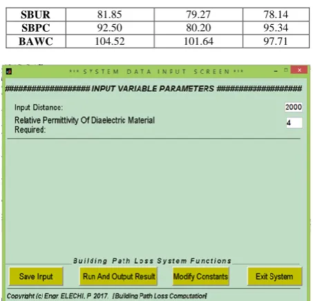
Figure 1: System Data Input Screen for Path Loss Computation
Figure 2: System Constant Input Screen
Figures 1 and 2 show the Matlab user interface for computation of GSM signal penetration loss using the developed model of equation (25). Figure 1 shows the input variable entry and the execution command such as „Run and Output Result‟, „Modify Constant‟, „Save Input‟ and „Exit‟. Figure 2 shows the system constant input screen for the modification of the in-building path loss exponent, etc.
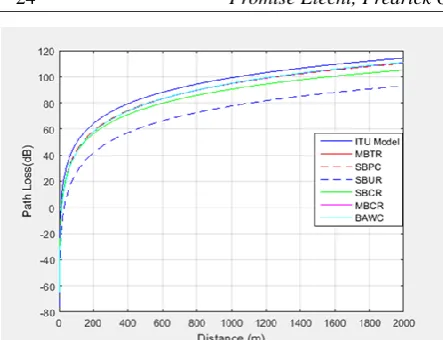
4.2: Comparison of Developed Model and ITU-R Indoor Attenuation Model
Figure 3: Comparison of Developed Model with ITU-R Model
IV. CONCLUSIONAND
RECOMMENDATIONS
A. Conclusion
In this work, measurements were conducted using Radio Frequency Signal Tracker to determine GSM signal loss in buildings in four different locations in Rivers State. The results showed the impact of different building materials on GSM received signal strength. In all the measurements, the results were analysed to determine the penetration loss and path loss exponents for each of the building materials considered. The results however showed that the building with alucoboard wall cladding had the maximum signal penetration loss while the Sandcrete building with unrusted corrugated iron sheet roof/PVC ceiling (SBUR) had the least signal penetration loss. The indoor losses also showed that the internal partitions/room demarcations also accounted for some losses in buildings. The results also showed that the concrete partitioning material had the highest signal loss while the wooden partitioning material had the least signal loss. The measurements data were also approximated using least square method and standard deviation. The measurement data was analysed and a model was developed, the result of which was compared with the ITU-R indoor path loss model. The comparison showed very close relationship.
The developed path loss model also showed that the building with alucoboard wall cladding also had the maximum signal penetration loss.
For each of the building materials considered, the path loss exponent varied between 0.87 to 1.32 while the entire path loss exponent from the transmitter to the receiver varied between 4.87 and 5.32 and with standard deviations between 17.0 dB to 17.8 dB. The standard deviation showed slight deviation indicating that the measurement data were clustered closely around the mean, hence, high accuracy.
This work has shown why subscribers inside a building experience network challenges. Subscribers receive signals outdoor but as soon as they move indoor, they are faced with the problem of lack of signal for effective communication. Hence, it will be
recommended that builders should always consider the selection of building materials during construction.
B. Recommendations
This research has presented a new model for predicting signal attenuation in an urban and rural environment based on the building material. Therefore, it is recommended that this study be extended to other buildings made with different materials such as screeded walls in and buildings in factories and industrial areas to determine their penetration loss.
To enhance GSM signal reception, the following suggestions if applied can serve as an option;
• Building developers should avoid the use of aesthetic materials such as alucoboard that can increase signal loss in beautifying houses.
• An enforcement of adequate housing spacing by the Government; this is because as the signals pass from one building to the other, the quality of the signals are reduced.
• There should be installation of more BTS in locations with high building density.
Further research should be carried out to improve signal quality in buildings such as screeding walls and asbestos ceiling.
REFERENCES
[1] P. Elechi, and P.O. Otasowie, “Determination of Path Loss Exponent for GSM Wireless Access in Rivers State using Building Penetration Loss,” The Mediterranean Journal of Electronics and Communication, vol. 11, no.1, 2015, pp. 822-830.
[2] P. Elechi, and P.O. Otasowie, “Analysis of a Developed Building Penetration Path Loss Model for GSM Wireless Access,” International Journal of Engineering Research and General Science, vol. 3, no. 6, 2015, pp. 898-909
[3] P. Elechi, and P.O. Otasowie, “Determination of GSM Signal Penetration Loss in Some Selected Buildings in Rivers State, Nigeria,” Nigeria Journal of Technology, vol. 34, no. 3, 2015, pp. 609-615.
[4] P. Elechi, “An Improved Signal Penetration Path Loss Model for GSM Network”, Global Summit on Electronic and Electrical Engineering, Valencia, Spain, 2015.
[5] P. Elechi and P.O. Otasowie, “Comparison of Empirical Path Loss Propagation Models with Building Penetration Path Loss Model”, International Journal on Communication Antenna and Propagation, vol.6, no. 2, pp. 854-861, 2016.
[6] P. Elechi and P.O. Otasowie, “Determination of Path Loss Exponent for GSM Wireless Access in Rivers State using Building Penetration Loss”, The Mediterranean journal of Electronic and Communications, vol. 11, no. 1, pp. 822-830, 2015.
[7] P. Elechi and P.O. Otasowie, “Path Loss Prediction Model for GSM Fixed Wireless Access”, European Journal of Engineering Research and Science, vol. 1, no. 1, pp. 7-11, 2016.
[8] S. Orike, P. Elechi, and I.A. Ekanem, “Assessment and Modeling of GSM Signal Propagation in Uyo, Nigeria”, European Journal of Engineering Research and Science, vol. 2, no. 11, 2017, pp. 49-58.
[9] P. Elechi and P.O. Otasowie, “Investigation of GSM Signal Loss in Multi-Storey Building”, International Conference and Exhibition on ICT and Telecommunications, Port Harcourt, Nigeria, pp. 65-72.
[11] J.O. Adewoye, & K.A. Obasa, “Impact of Global System for Mobile Communication on Small Business Development”, Journal of Management and Society, vol. 1, No. 2, pp. 44-50, 2010.
[12] J.B. Andersen, T.S. Rappaport, & S. Yoshida, “Propagation Measurements and Models for wireless Communications Channels”, Institution of Electrical Electronic Engineers Communication Magazine, vol. 33, No. 1, pp. 42-49, 1995. [13] C.R. Anderson, T.S. Rappaport, K. Bae, A. Verstak, N.
Ramakrishnan, W.H. Tranter, C.A. Shaffer, & L.T. Watson. “In-Building Wideband Multipath Characteristics at 2.5 and 60GHz”, Institution of Electrical Electronic Engineers conference on Wireless Communication, vol. 41, No. 5, pp. 97-101, 2010.
[14] P. Ångskog, “Measurement and Analysis of Radio Wave Coverage in Industrial Environments”, Master‟s Thesis, Department of Electrical Engineering, University of Gavle, pp.5-7, 2012.
[15] T.A. Danladi, A.U. Lawan, & M. Aderinola, “Studies and Effects of Building Pattern on Downlink Mobile Phone Signal Strengths and Power Loss”, International Journal of Engineering and Science, vol. 2, No. 12, pp. 24-29, 2013. [16] G. Durgin, T.S. Rappaport, & H. Hu. “Radio Path Loss and
Penetration Loss Measurements in and around Homes and Trees at 5.85GHz”, Mobile and Portable Radio Research Group Journal, pp. 1-4, 2002.
[17] N. Faruk, A.A. Ayeni, & Y.A. Adediran, “Characterization of Propagation Path Loss at VHF/UHF Bands for Ilorin City, Nigeria”. Nigerian Journal of Technology, vol. 32, No. 2, pp. 253-265, 2013.
[18] L. Ferreira, M. Kuipers, C. Rodrigues, & L.M. Correia, “Characterisation of Signal Penetration into Buildings for GSM and UMTS”, Department of Electrical Engineering, Technical University of Lisbon: pp. 2-3, 2012.
[19] http://www.microwave101.com. Visited on 28/08/2016 [20] A.I. Idim, & F.I. Anyasi, “Determination of Building
Penetration Loss of GSM Signals”, Journal of Electronics and Communication Engineering, vol. 9, No. 5, pp. 1-5, 2014. [21] A.I. Idim, & F.I. Anyasi, “Determination of Path Loss
Exponent using GSM Signals in Orhuwhorun Environment, Delta State”, Journal of Electronics and Communication Engineering, vol. 9, No. 5, pp. 12-20, 2014.
[22] International Telecommunications Union, ITU-R Recommendation 527-3: Electrical Characteristics of the Surface of the Earth, Geneva, 1992.
[23] A Mitra, Lecture Notes on Mobile Communication, Department of Electronics and Communication Engineering, Indian Institute of Technology, Guwahati, India, 2009. [24] J.C. Ogbulezie, M.U. Onuu, D.E. Bassey, & S.
Etienam-Umoh, “Site Specific Measurements and Propagation Models for GSM in Three Cities in Northern Nigeria”, American Journal of Scientific and Industrial Research, vol. 4, No. 2, pp. 238-245, 2013.