Volume 21 (2009)
Proceedings of the
3
rdInternational Workshop on
Multi-Paradigm Modeling
(MPM 2009)
Synthesizing Executable Simulations from Structural
Models of Component-Based Systems
Andreas Schuster and Jonathan Sprinkle
10 pages
Guest Editors: T. Levendovszky, L. Lengyel, G. Karsai, C. Hardebolle Managing Editors: Tiziana Margaria, Julia Padberg, Gabriele Taentzer
Synthesizing Executable Simulations from Structural
Models of Component-Based Systems
Andreas Schuster1and Jonathan Sprinkle2
1Technische Universit¨at Berlin, [email protected] 2University of Arizona, [email protected]
Abstract: Experts in robotics systems have developed substantial software tools for simulation, execution, and hardware-in-the-loop testing. Unfortunately, many of these robotics-domainsoftwareinfrastructures pose challenges for a robotics expert to use, unless that robotics expert is also familiar with middleware programming, and the integration of heterogeneous simulation tools. In this paper, we describe a novel modeling language designed to bridge these two domains in an intuitive visual representation. Using this metamodel-defined modeling language, we can design and build structural models of robotics systems, and synthesize experiments from these constructed models. The restrictions implicit (and explicit) in the visual language guide modelers to build onlymodels that can be synthesized, a “correct by construction” approach. We discuss the impact of this language with a running example of an autonomous ground vehicle, and the hundreds of configuration pa-rameters and several simulation tools that are necessary in order to simulate this complex example.
Keywords:Metamodeling, heterogeneous simulation, configuration synthesis
1
Introduction
The miniaturization of computing power has enabled bold advancements within the robotics community in recent years. Commodity hardware is now used for software-enabled sensing and control on vehicles that were previously limited to embedded control (i.e., micro-controller) technology. Chief among the technologies that permits control, computation, and communica-tion on such robotic vehicles—and indeed, between teams of robotic vehicles—is middleware, which abstracts the location and operating system of various functional components.
Component-based software engineering (CBSE) is a system development approach that per-mits functional behaviors of components to be generalized for reuse. Components run asyn-chronously and exchange information through communication. In order to be generalized, many components can be developed with various parameters which are read at initialization time, and permit software reuse across various sensor families, actuator designs, or computational con-straints and preferences [MBK07]. When used effectively, CBSE provides abstraction of com-munication (network, inter-process), distribution (multicore, distributed computers), implemen-tation (language, OS), and interface (XML, objects, streams).
validated, and subjected to regression tests on a regular basis [S+09]. For robotics systems, one difficulty in building reliable software arises from the task’s complexity [MBK07] and its dynamic real-time nature. Additional factors, including the distributed and cross-platform com-puting environment, the large number of software contributors, and the desire to use existing code increase the difficulty. As projects increase in size, the complexity of running simulations or creating tests similarly increases. Many such projects employ domain experts who have de-veloped a proof of concept of their algorithm in a CBSE language, incorporating the various middleware types into the specification of their algorithm.
In a robotic system such as an autonomous vehicle, algorithms for perception, navigation, con-trol, and logging are mapped to a set of components. The integration of these components is gen-erally completed using the mechanisms available in a middleware technology. However, some domain-specific abstraction can be additionally gained by the application of robotic-specific mid-dleware, as seen in the projects Gearbox [MBK07], Player/Stage [CMG05], Orocos [BSK03], Microsoft Robotics Studio [Che07], etc. Such tools make it possible to define and develop building-blocks that can be pieced together to form arbitrarily complex robotic systems, from single vehicles to distributed sensor networks.
1.1 Configuration Explosion
Understanding the intersection of modeling and simulation (discussed in detail in [VLM02]) is a key goal of multi-paradigm modeling. In the application we discuss in this paper, the model of the system can help to manage the configuration explosion problem, while simultaneously serving as the necessary specification for simulation of the entire system.
Each component has a static configuration space, and in many cases, components can run with no configuration, based on value defaults encoded in the component software. However, in order to perform regression tests, or maintain the current running version of a robot, configuration files must be managed. From the perspective of good system design, ad hoc management has several problems. New members of a project may be encouraged to look at, or clone, existing configuration files to run the simulation. This is problematic if members do not understand the entire configuration space, or if configuration spaces of more than one tool overlap in a single file. For instance, information on default communication ports may be included in a server configuration file (an installation directory), and overridden in user files (a home directory), or even in simulation configuration files (the directory housing simulation-specific files).
However, the most frustrating part of configuration explosion is its impact on existing domain experts (not middleware experts), who cannot rapidly distinguish between errors in the code, and errors in configuration. Thus, tremendous effort could be wasted in determining whether component experts should be involved, or whether the system setup is using invalid assumptions or values from another computer or simulation scenario.
1.2 Structural Specification
In this paper, we propose an integrated modeling solution for component-based software systems which utilize layered middleware as the communication and implementation technology. Our provided solution is a constrained graphical modeling language that provides a semantic map-ping to the configuration space of an existing robotics middleware package, namely the Orca Robotics platform. We provide the details of the structural specification of such experiments, and algorithms necessary to synthesize the configuration options for them. Further, we provide several informal design patterns that lend themselves to reduce copy/paste duplication.
2
Background and Related Work
Researchers have recently seen significant success in the application of component-based tech-nologies to mobile robots. In this approach, large systems are decomposed into atomic nents that can be reused in other applications. From a domain-specific perspective, each compo-nent provides some processed data or control inputs based on existing inputs, or samples from the physical system. Even if one applies this component-based approach, the application domain may be complex and characterized by large variability in hardware and software configurations. As a result, virtually every new system requires a custom design [MBK07]. Regrettably, soft-ware components may be difficult to understand, or lack documentation for their input/output relationships, and this may result in software being rewritten rather than reused.
In recent work a number of different projects for robotics and real-time systems have ad-dressed the issue of code duplication through the creation of software frameworks [BSK03, S+02, MBK06,Che07] Common in each of these frameworks is the goal to improve software reuse: those that are component-based define how interfaces should be specified (for the devel-opment of new components), as well as how components can be assembled (for the application of existing components). Many of these projects provide a repository of already working compo-nents, thus enabling the rapid assembly of components with little or nocodingeffort. As we have pointed out, though, the effort to perform reconfiguration of such components can be nontrivial.
2.1 Existing CBSE Technologies
Middleware and component-based technologies facilitate the abstraction of communication, and location of computation. Microsoft’s COM+, and .NET technology provide some degree of language freedom, though they require to some extent a Windows execution environment. En-terprise Java Beans, and SOAP, each support a similar technology, permitting an abstraction of provided data types for particular components.
somewhat disjoint, though in this paper we do not comment on their relative advantages, leaving this as a design decision for implementors.
2.2 Distributed Real-Time Embedded (DRE) Systems
When it comes to distributed real-time and embedded (DRE) systems, applications have his-torically been manually programmed and customized [S+02]. To address the problems with developing and customizing DRE systems from scratch, there is growing interest in composing these types of systems using commercial off-the-shelf (COTS) hardware and software.
An existing approach to address middleware-specific component composition is the Compo-nent Synthesis using Model Integrated Computing(CoSMIC) project. The CoSMIC toolsuite is designed to (1) model and analyze DRE application functionality and QoS requirements and (2) synthesize CCM-specific deployment metadata for CIAO and QuO required to provision and enforce end-to-end QoS both statically and dynamically [S+02]. This toolsuite is similar to our approach, though we focus our work on families of experiments for collections of components for novice users, rather than advanced scheduling and deployment for generic CCM models.
2.3 Models of Heterogenous Software Simulation
There is existing work in the simulation of heterogeneous software systems. A large body of work for discrete event simulation, namely using the DEVS tool, provides significant insight into the technologies requires to simulate discrete event systems. The DEVS framework, or similar technology, can also be used as a uniting model of computation for systems using heterogeneous simulation environments.
The Command and Control (C2) Wind Tunnel is an example of heterogeneous simulation of software systems [G+09]. This application provides a unified model for the structure of the system specification, and uses code generation to provide language-specific hooks for a diverse suite of programming environments, including MATLAB, Java, C++, and Colored Petri Nets. Communication is performed through the HLA middleware, and networks are simulated at the packet level to permit sophisticated experimentation with latency and network attack.
2.4 The Orca Robotics Project
We describe in some detail the configuration space of the Orca Robotics Project, since this frame-work is the one to which we semantically map our structural models. Orca is an open-source software framework for developing robotic systems [MBK06]. It considers itself as an imple-mentation framework and not an architecture, meaning that developers may run their systems on any kind of network as long as the interfaces of their components are appropriately connected. Operating systems known to support Orca components include Linux, QNX Neutrino, and Win-dows XP. Such a diverse array of operating systems permits hard, and soft, real-time, execution of algorithms, providing additional accuracy for sensed data if necessary.
configuration parameters for each component, as well as an executable version of the configured system. To concretely ground our synthesis approach, we give some abbreviated examples of configuration files, rather than specify their abstract syntax; however, the abstract syntax of these files was useful in the specification of the semantic mapping.
As a matter of interest, previous releases of the Orca framework provided a GUI to provide a similar method of specification of configuration files. However, the solution we discuss provides a more configurable, and also more structured, modeling environment, with significant opportu-nities for extension. Moreover, the later releases do not provide this GUI as most users of Orca are power users, and do not need the graphical syntax.
2.5 Contribution
We differ from the previous Orca GUI in the following ways: we provide an environment where previous experiments can be easily archived, and to which future experiments can refer (e.g., using the GME-specific types of reference, or types/instances). We differ significantly from the CoSMIC approach in that our goal is not to generically service middleware specification as an architecture-description language. Our approach is a more domain-specific one, for ex-perts whose experiments are frequently repeated with various parameter values, or topologically changed with instances of existing/multiple components.
Thus, it is imperative that we permit synthesis of experiments from the topology of the com-ponent diagram, and various input/output relationships that exist by definition. Our approach provides a configurable graphical environment that will permit new users to easily configure their experiments and begin to use the framework with confidence.
2.6 Configuration Files
Configuration files list properties as key/value pairs, and they generally consist of four sections: (1) component identity; (2) provided interfaces; (3) required interfaces; and (4) component con-figuration options. Item (1) is the only required element of a concon-figuration file, and it is needed to enable the communication between different components, as well as establish the unique identity of this component on the network. In Figure1we show an example configuration file.
Provided interfaces are specified by name, and this name is hashed together with the compo-nent identity and platform in order for others to have a unique subscription. Compocompo-nents that are sinks will not provide any interfaces. Required interfaces are specified similarly. One can either use “direct” or “indirect” binding, selecting either the interface name (and port ID), or the platform/component combination. Generally, an indirect binding is preferred, to permit the middleware to abstract the communication ports from the system constructor.
# Component
COMP_TAG.Platform=p1
COMP_TAG.Component=c1 COMP_TAG.Endpoints=e1 # Provided interfaces
COMP_TAG.Provides.IFACE_TAG1.Name=i1 COMP_TAG.Provides.IFACE_TAG2.Name=i2
# Required interfaces # Direct binding
COMP_TAG.Requires.IFACE_TAG1.Proxy=i1:e1 # Indirect binding
COMP_TAG.Requires.IFACE_TAG2.Proxy=i2@p1/c1
# Configuration Options
COMP_TAG.Config.SET_TAG1.PARAM_TAG1=0.1
COMP_TAG.Config.SET_TAG1.SET_TAG2.PARAM_TAG2=1
Figure 1: Sample component identity, provided, and required sections.
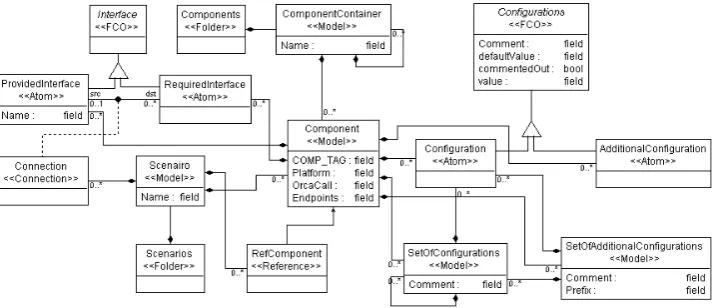
Figure 2: Metamodel
3
Language Specification
Our approach to provide an intuitive specification environment, as well as a fully-featured constraint-based language involves the development of a metamodel. We developed the language and all translators in the GME toolsuite [LBM+01].
Our language centers around theComponenttype. As one can see in figure Figure2it contains four attributes described in table Table1. We discuss briefly the significance of theInstanceName
attribute. In the event that a platform requires more than one instance of the same component (e.g., multiple laser scanners on a platform), then each component can use a different configura-tion file. Importantly, the applicaconfigura-tion that simulates or interfaces with the laser scanner would be the same both times, but would read from a different configuration file.
Like-Table 1: Attributes of the Type Component
GME Attr Orca Configuration Mapping COMP TAG Maps to theCOMP TAG
Platform Maps to the keyPlatform
Endpoints Maps to the value to the keyEndpoints
InstanceName Instance-specific name of this component and associated configuration file
wise,RequiredInterfacetypes correspond to interfaces to which this component must subscribe.
Configurationtypes and subtypes can be composed in order to permit the hierarchical structure shown in Figure1. Using the various parameter values of these types, boolean, string, integer, and floating point parameters can be enforced for parameter types. The typeSetOfConfigurations
enables the modeler to group configurations together, where all configuration options in a set of configurations will have the sameSET TAG. In addition a set of configurations can contain other set of configurations. This allows the modeler to nest sets in a arbitrary depth of hierarchy.
Semantically ConfigurationandAdditionalConfigurationdiffer in that theCOMP TAGis not found for generated text ofAdditionalConfiguarationoptions unless explicitly given as the value. This permits compatibility with components developed outside the style guide of Orca, and is extended forSetOfAdditionalConfigurationsto permit composition.
In order to enforce the so calledstatic semanticsof our language we developed constraints, which restrict some (normally allowed) syntax patterns when used in certain contexts. These constraints are expressed in an extension of OCL available in GME, and can be seen in Figure3. One constraint is that the attributesCOMP TAGandInstanceNameare explicitly set. They are both absolutely essential, and this constraint ensures that they are not omitted accidentally1. The more subtle constraint attached toRequiredInterface types ensures that a required interface is connected to no more than one provided interface. While a provided interface can deliver data to any number of required interfaces, it does not make sense to have more than one source for one required interface.
After the modeler has built her model of this scenario, she wants to generate the output files that will represent and execute this experiment. The semantic map from the metamodel to our application domain performs this mapping through a series of traversals.
Our first traversal produces one configuration file for each component in this scenario, a straightforward process based on a direct map from the component model’s contained config-uration options, and the source and destination component ports for each produced and required interface. The second traversal examines the data dependencies of the component graph, and
1Note that in GME, graphical cardinalities at the diagram level are not enforced for associations.
Component.COMP_TAG.trim() <> "" ...
RequiredInterface.connectedFCOs("src")->size <= 1
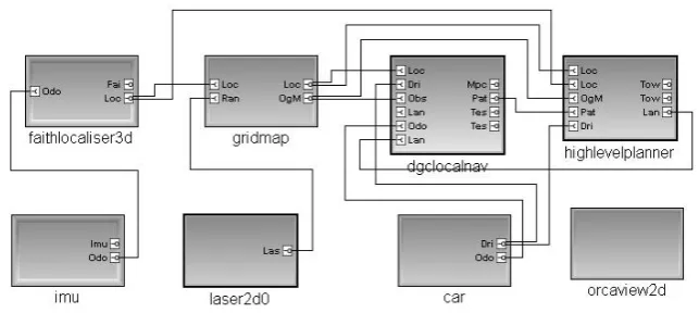
Figure 4: Running Example
synthesizes a standalone script to start up components in the appropriate order. Included in this script is the necessary order and timing of the startup of third party tools such as a physical system simulator, and middleware core services such as the registry and cache databases.
4
Example Simulation
Figure4shows an example model, which evolved during the development of our language. Each of the eight blocks in Figure4 represents one component, and makes up the simulation of an autonomous vehicle. The model interpreter examines the data dependencies of the component models, and produces a script that (1) starts up necessary network interfaces, (2) initiates physi-cal/network simulators, (3) initializes and starts each component with the specified parameters, (4) logs the data to a unique output file. This simulation capability is key to our approach, in that the dependable startup order and parameter values are explicit and implicit in our specification, rather than depending on user training.
We used three different runtime types to put together this model. The blocks with the thickest frames (faithlocaliser3dandimu) are models which were created inside theScenario
model. The blocks with the same type of, but thinner frame (gridmap,carandorcaview2d) are instances of prototype models that are created within a component container; i.e., they are instantiations of a library of components. The third type of blocks with the solid, black frame (dgclocalnav,highlevelplannerandlaser2d0) are references (pointers) to models that are created in a component container.
If the modeler wants to use the same component, but with different attributes, within the same experiment, she will want to use instances of prototypes, or copies of the models. Instances of prototype models have the same structure and attributes of those prototypes, but one is able to change the values for those attributes independently from each other. If a modeler wants to provide her component database to the public, but has a few components that are not supposed to be published, she will be able to create those components directly in an experiment.
5
Analysis
For the simulation presented in Section4a total of 360 lines of code were generated: 70 in the startup script and 290 in configuration files. Although a domain expert can create the script file rapidly (through cloning another one), this is not feasible for new users of the simulation envi-ronment, and thus the startup costs for a new user are significantly reduced through the use of this environment. Once a model in our language exists, it is a question of seconds to generate all files at once. The steps needed to uniquely reconfigure an experiment have also been reduced. Component addition or deletion is now handled graphically, and component interconnection is trivial with line-drawing capabilities (and explicit constraints) of the tool. Earlier when includ-ing a new component, one should be familiar with existinclud-ing configuration files to reuse them as new. Now, it is enough to create a visual representation (model) of the new component and the configuration file will be generated automatically.
Another advantage of our visual language that should not be underrated is the documentation that comes with the creation of a model of an experiment. The model shows what components take part and how they are connected to each other. It now is very easy for an robotic expert and even for a layman to understand the overall design.
This perspective of our approach distinguishes this from an approach that does not involve model-based design. In fact, the number of users of the Orca environment is somewhat limited, due to the expertise needed to understand the experiment topologies well. We believe that our approach will permit a wider audience to take advantage of the Orca toolbox. Further, we can now take advantage of many of the benefits of the GME toolsuite, to rewrite component diagrams for advanced purposes, such as synthesis of time-triggered scheduling buffers [SE09].
Although our example is certainly possible to produce without a model-based approach, the model-based approach rapidly introduces new team members to the design, and permits them to make contributions much more quickly. Future work with this environment has the potential to reduce effort for even advanced users.
6
Conclusion and Future Work
Bibliography
[BSK03] H. Bruyninckx, P. Soetens, B. Koninckx. The Real-Time Motion Control Core of the Orocos Project. InIEEE International Conference on Robotics and Automation. Pp. 2766–2771. 2003.
[Che07] S. Cherry. Robots Incorporated.Spectrum, IEEE44(8):24–29, Aug. 2007.
[CMG05] T. Collett, B. MacDonald, B. Gerkey. Player 2.0: Toward a practical robot program-ming framework. In Proceedings of the Australasian Conference on Robotics and Automation (ACRA 2005). 2005.
[G+09] J. Gulotta et al. Using Integrative Models in an Advanced Heterogeneous System Simulation. InEngineering of Computer-Based Systems, IEEE International Con-ference on the. Pp. 3–10. IEEE Computer Society, Los Alamitos, CA, USA, 2009.
[Hen04] M. Henning. A new approach to object-oriented middleware.IEEE Internet Com-puting8(1):66–75, 2004.
[LBM+01] ´Akos L´edeczi, ´Arpad Bakay, M. Maroti, P. Volgyesi, G. Nordstrom, J. Sprin-kle, G. Karsai. Composing Domain-Specific Design Environments.IEEE Computer
34(11):44–51, November 2001.
[MBK06] A. Makarenko, A. Brooks, T. Kaupp. Orca: Components for robotics. In Interna-tional Conference on Intelligent Robots and Systems (IROS). Pp. 163–168. 2006.
[MBK07] A. Makarenko, A. Brooks, T. Kaupp. On the Benefits of Making Robotic Software Frameworks Thin. In Prassler et al. (eds.),IEEE/RSJ Int. Conf. on Intelligent Robots and Systems (IROS’07) Workshop on Measures and Procedures for the Evaluation of Robot Architectures and Middleware. November 2007.
[S+02] D. Schmidt et al. CoSMIC: An MDA generative tool for distributed real-time and embedded component middleware and applications. InOOPSLA Workshop on Gen-erative Techniques in the Context of Model Driven Architecture, Seattle, WA. 2002.
[S+09] J. Sprinkle et al. Model-based design: a report from the trenches of the DARPA Urban Challenge.Software and Systems Modeling8(4):551–566, September 2009.
[SE09] J. Sprinkle, B. Eames. Model-Based Autosynthesis of Time-Triggered Buffers for Event-Based Middleware Systems. In9th OOPSLA Workshop on Domain-Specific Modeling. P. (to appear). October 2009.