ISSN 2347-4289
Calibration Method For Height Measurement Of
Object Using Laser Triangulation
Rameshwar Ashok Wagh, Dr. M.S.Panse, Hemant Apte
MTech Research Scholar, Electrical Engineering Department,Veermata Jijabai Technological Institute (VJTI), Mumbai, India; Professor Electrical Engineering Department,Veermata Jijabai Technological Institute (VJTI), Mumbai, India;
Managing director, Univision Softech Pvt Ltd., Mumbai, India
[email protected], [email protected], [email protected]
ABSTRACT: Machine vision has been adopted in numerous industries since it eliminates need of human involvement and provides considerable accuracy along with splendid speed. Laser triangulation has brought a new era in measurement enabling measurement in third dimension. Still due to nonlinearities present in camera and laser sensor, it is difficult to apply this principle universally for large range of heights. In this regard, a piecewise linear calibration system is proposed in this paper. This system enables the sensor to cover considerably large working range with more precision. Actual set of objects are measured and readings are compared with respect to error and standard deviation.
Keywords:Laser triangulation; machine vision; height measurement; calibration.
1
I
NTRODUCTIONMEASUREMENTS play a vital and inevitable role in Industries. For every part of product produced in industry, there are some specified measurements, failing to achieve which, may cause product to lose its usefulness and hence value. These mea-surements are done by automated systems or if require, few of them also have human involvement.Height measurement of objects is often a difficult task. If machine vision is used, then two dimensions of object are seen and can be measured. But when it comes to height of object or depths in object, mere 2D camera is not sufficient. Unless there is any relative reference for height or depth, it is very difficult to conceive the third di-mension. In LASER triangulation, a LASER line pointed on a surface acts as the reference. When either laser or camera is at an angle, and there is object between laser and the surface, camera can sense change in height through image. Then ex-act height can be calculated from various parameters. Height measurement principle using laser triangulation is explained in this paper. There are nonlinearities involved while implementing this simple principle. Depth of focus for a lens and lens distortion are major of them. Due to these properties of lens, triangulation principle works in a very limited range of height. Camera is calibrated for lens distortion [1][7], still complete setup needs to be calibrated for accurate measurements and repeatability. Using the setup as shown in fig. 1, a calibration approach is proposed in this paper. Increasing precision of the sensors and lasers, system also can be used for surface profiling of object. Eventually, complete 3D profile of an object can be prepared by acquiring height, width and length information from a single camera.
2
P
RINCIPLE2.1 Laser Triangulation
Triangulation is a method based on, geometry of a triangle for measuring distance of one of the vertices of triangle from the line joining other two vertices. Knowing length of a side and angles from the side to the third vertex, distance of third vertex is easy to find.
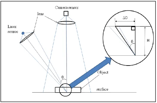
Fig.1. Principle of Laser triangulation
In Laser triangulation, a line laser is used to get parameters which are used in trigonometric relations to get distance of third point from the base line. This technique is used here to get height of object. Camera and a line laser are two basic needs of this technique. Camera and laser can be at any an-gle, but specifically camera here is at right angle[2][3]. Fig.1 Shows the geometry of camera, laser and the surface. Length of known side is D which is displaced position of laser line with respect to original one [4]. Here since one of the angles from known side is 900, calculations are very easy to find height H of object. Relation can be seen as [3]
H = △D / (tan θ) (1)
2.2 Implementation of laser triangulation principle Equation (1) shows that if angle θ is known, then height of object is directly proportional to the distance of displaced laser line which is △D. Since camera is used to measure △D, a scal-ing factor comes into picture. This scalscal-ing factor is a conver-sion factor for pixels to mm converconver-sion. Hence (1) changes to
ISSN 2347-4289
Before applying this equation in image, some basic image processing is necessary so as to get accurate readings from image.
2.3 Image Processing Algorithm
When image is captured with the camera, it consists of un-wanted intensities and blurring. These phenomenons can be eliminated by using proper filtering technique. Since intensities of pixels illuminated due to laser line are most important, dur-ing line extraction, their integrity should be maintained. Hence during filtering these pixels should be untouched. Here prima-ry challenge is to extract exact impact points of laser. As can be seen in Fig 1, middle line coming out of laser shows plane of impact. But since line laser is not ideal one, it has finite thickness at the impact position; a triangular volume is formed altogether instead of just single plane of impact. Hence, vari-ous methods were applied for considering line of impact for triangulation.
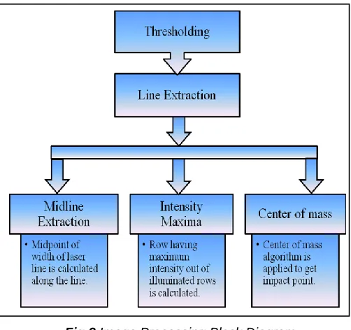
Fig.2 Image Processing Block Diagram
Fig. 2 shows image processing in the form of block diagram.
2.3.1 Thresholding:
Image captured by camera has some spurious components other than intended data. Those components are removed by filtering. In this process, a threshold level for intensity is de-fined. All the pixels below that threshold levels are made zero and the remaining pixels are left untouched. These pixels are then used for line extraction. Fig.3 shows original image cap-tured by camera which shows laser line deviation due to pres-ence of object. Fig.4 shows image obtained after thresholding operation.
2.3.2 Line Extraction:
Fig. 2 shows three algorithms for extracting exact position of laser line. When laser is illuminated on an object, laser line has certain width. In midline extraction technique [5], midpoint of the thicker laser line is calculated throughout the line. In intensity maxima technique also known as maximum peak [5], row of pixel having maximum intensity is considered as impact position of the laser. Center of Mass method is weighted
aver-age of pixel intensities. Various pixels intensities act as weights. Out of these algorithms, Center of mass is most relia-ble technique [3]. In midline extraction, since midpoint is found out, maximum resolution of △D is limited to 0.5 pixels. In in-tensity maxima, maximum inin-tensity pixels form impact line, hence maximum resolution is 1 pixel. Center of mass since takes weighted average of intensities in a column; it is not bounded by any specific resolution. Here in this paper center of mass technique is used for line extraction.
Fig.3 Original image with laser line incident on object
Fig.4 Image after thresholding
3
C
ALIBRATIONBefore the setup is used for height measurement, it has to be calibrated. Once setup is calibrated for certain height, it can be used for measurement. Various calibration methods are avail-able [6]. Though (2) shows that height is directly proportional to deviation (△D), in actuality, relation does not hold over the larger range of height. Also, if system is calibrated for large measuring range, considering whole range at once, system loses its accuracy. So there is tradeoff between length of measuring range and system accuracy. Hence for calibration, piecewise linearization approach is proposed here. In this
ISSN 2347-4289
proach, overall measuring range and corresponding deviation in laser line is divided into number of segments. Relation be-tween deviation in laser line and height is defined individually for each segment using best fit algorithm. Here system is cali-brated for height of 48 millimeters. Objects with known heights were taken for calibration and deviation in laser line for respec-tive laser line was noted. System was calibrated with whole range considered as different number of segments. First, complete range of 48 millimeters is considered as a single segment, and best fit algorithm is applied for finding relation between △D and actual height. Then whole range is divided into two segments of 24 millimeters each and for each seg-ment, best fit algorithm is applied. Same procedure is applied with range divided into three and four segments with each segment of range 16 millimeters and 12 millimeters respective-ly. Sixth order best fit polynomial function was used to cali-brate full range of measurement as a single segment and the same calibration was also done by best fit line function. (3) and (4) shows respective equations.
H = a1* x6 –a2* x5 + a3 * x4+ a4 * x3- a5* x2 +a6 * x - a7 (3)
x = △D
a1=3E-12, a2=8E-10, a3=6E-08, a4=5E-06, a5=0.001, a6=0.415, a7= - 0.192
H = 0.331(△D) + 1.436 (4)
Results are tabulated in Table 1. It can be seen that, if best fit polynomial method is applied for calibration, then error in-creases with increasing height. Error is considerably small in the case when calibration is done by best fit line algorithm. Hence for further calibration, best fit line algorithm is used.
4
M
EASUREMENTR
ESULTSOnce setup is calibrated, objects with 2 millimeter height are stacked up and measured for height. Table 1 enlist real height of object (H) in millimeters, deviation in laser line due to non-zero height of object(△D) in pixels, corresponding measured height and absolute error in measurement (|H-Hobj|). All the readings are taken by a system calibrated with complete mea-suring range of 48 millimeters considered as a single segment. Table 2 has similar measurements of measured height and error with systems calibrated with two segments, three seg-ments and four segseg-ments. Table 3 tabulates average absolute error for measurements made with all the four systems.
TABLE I. MEASUREMENT WITH SYSTEM CALIBRATED WITH COMPLETE RANGE AS A SINGLE SEGMENT
Real Ht. (H)
△D Measured Height(H
obj)
Error |H-Hobj|
Best Fit Line
Best Fit Poly.
Best Fit Line
Best Fit Poly. mm pixels mm mm Mm mm
1.98 5.31 3.19 1.98 1.21 0.00
3.97 10.27 4.84 3.97 0.87 0.00
6.00 15.55 6.58 6.04 0.58 0.04
8.02 20.97 8.38 8.13 0.36 0.11
10.01 25.91 10.01 9.99 0.00 0.02
Real Ht. (H)
△D Measured Height(Hobj)
Error |H-Hobj|
Best Fit Line
Best Fit Poly.
Best Fit Line
Best Fit Poly. mm pixels mm mm Mm mm
12.02 31.71 11.93 12.16 0.09 0.14
14.03 37.41 13.82 14.26 0.21 0.23
16.03 43.07 15.69 16.33 0.34 0.30
18.05 48.67 17.55 18.37 0.50 0.32
20.05 54.53 19.49 20.50 0.56 0.45
22.05 60.37 21.42 22.62 0.63 0.57
24.05 66.16 23.34 24.72 0.71 0.67
26.06 72.26 25.35 26.95 0.71 0.89
28.08 78.48 27.41 29.23 0.67 1.15
30.08 84.54 29.42 31.47 0.66 1.39
32.10 90.85 31.51 33.83 0.59 1.73
34.14 97.19 33.60 36.23 0.54 2.09
36.14 103.56 35.72 38.69 0.43 2.55
38.18 110.27 37.93 41.34 0.25 3.16
40.16 116.93 40.14 44.05 0.02 3.89
42.15 123.65 42.36 46.91 0.21 4.76
44.18 130.60 44.66 50.03 0.48 5.85
46.22 137.60 46.98 53.41 0.76 7.19
48.25 144.32 49.21 56.95 0.96 8.70
TABLE II. MEASUREMENT WITH SYSTEM CALIBRATED WITH
COM-PLETE DIVIDED INTO VARIOUS SEGMENTS
Real Heigh t
Measurement with Two Segments
Measurement with Three Segments
Measurement with Four Seg-ments
H Hobj |H-H
obj| Hobj
|H-Hobj| Hobj |H-Hobj|
mm mm mm mm Mm mm mm
1.98 2.30 0.32 2.14 0.16 2.05 0.07
3.97 4.09 0.12 3.98 0.01 3.94 0.03
6.00 6.00 0.00 5.94 0.06 5.95 0.05
8.02 7.95 0.07 7.95 0.07 8.01 0.01
10.01 9.74 0.27 9.78 0.23 10.01 0.00
12.02 11.83 0.19 11.93 0.09 12.03 0.01
14.03 13.89 0.14 14.05 0.02 14.02 0.01
16.03 15.93 0.10 16.14 0.11 16.00 0.03
18.05 17.96 0.10 18.01 0.04 17.95 0.10
20.05 20.07 0.02 19.98 0.07 20.00 0.05
22.05 22.18 0.13 21.93 0.12 22.04 0.02
24.05 24.27 0.22 23.87 0.18 24.04 0.01
26.06 26.26 0.20 25.91 0.15 26.01 0.06
ISSN 2347-4289
Real Heigh t
Measurement with Two Segments
Measurement with Three Segments
Measurement with Four Seg-ments
H Hobj
|H-Hobj| Hobj
|H-Hobj| Hobj |H-Hobj|
mm mm mm mm Mm mm mm
30.08 30.02 0.07 30.03 0.05 29.97 0.11
32.1 31.94 0.16 32.14 0.04 32.01 0.09
34.14 33.88 0.26 34.12 0.02 34.06 0.08
36.14 35.84 0.31 36.04 0.10 36.17 0.03
38.18 37.89 0.29 38.05 0.13 38.16 0.03
40.16 39.93 0.24 40.05 0.11 40.13 0.03
42.15 41.98 0.17 42.06 0.09 42.12 0.04
44.18 44.11 0.07 44.15 0.04 44.17 0.01
46.22 46.25 0.03 46.25 0.03 46.24 0.02
48.25 48.31 0.06 48.26 0.01 48.23 0.02
TABLE III COMPARISON OF AVERAGE ABSOLUTE ERROR
Single Segment Method
Two Segments Methods
Three Segments Method
Four Segments Method mm mm Mm mm Absolute
Error 0.51 0.15 0.08 0.04
5
C
OMPARISON OFM
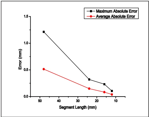
ETHODSFrom Table 1, Table 2 and Table 3, it can be seen that dividing measurement range into more segments, gives lesser error. Fig. 5 shows that absolute maximum error and absolute aver-age error decrease with increase in number of segments. For segment of length 48 millimeters, maximum error is 1.21 milli-metres and the average error is 0.51 millimilli-metres. For system calibrated with each segment of 12 millimetres, maximum error is 0.11 millimetres and average error is 0.04 millimetres.
Fig. 5 Segment Length Vs Error
Fig. 6 Segment Range Vs Average Standard Deviation in Er-ror
Fig. 6 shows average standard deviation in error for various segment lengths. It shows that the standard deviation is max-imum when complete range of 48 millimeters is covered in single segment. On the other hand, when range is divided into 4 segments, with each segment of 12 millimeters, standard deviation is minimum.
6
C
ONCLUSIONA
NDF
UTURES
COPEIn this paper, laser triangulation principle along with the im-plementation is discussed. Image processing for parameter extraction is discussed and results are shown. For overcoming limitations on measurement range, a new calibration method is proposed and its implementation is described. Results ob-tained by calibration methods are compared on the basis of error and standard deviation. It is found that with multiple segments calibration, error reduces and repeatability signifi-cantly increases. In future, profile formation of object surface will be studied and implemented. This will enable 3D mea-surement of object.
R
EFERENCES[1] Demeyere, M.; Rurimunzu, D.; Eugene, C., "Diameter Measurement of Spherical Objects by Laser Triangulation in an Ambulatory Context," Instrumentation and Measurement, IEEE Transactions on , vol.56, no.3, pp.867,872, June 2007
[2] Ferreira Barreto, S.V.; Eskinazi Sant'Anna, R.; Feitosa, M.A.F., "A method for image processing and distance measuring based on laser distance triangulation," Electronics, Circuits, and Systems (ICECS), 2013 IEEE 20th International Conference on , vol., no., pp.695,698, 8-11 Dec. 2013.
ISSN 2347-4289
[4] Yang-Cheng Lin; Pin-Hao Hu; Kuang-Yao Huang; Yung-Hsing Wang; Shun-Sheng Ko; Chien-Sheng Liu, "Design and characterization of laser-based inspection system," SICE Annual Conference (SICE), 2012 Proceedings of , vol., no., pp.1062,1066, 20-23 Aug. 2012.
[5] Lei Zhang; Mingyang Zhao; Yuanyuan Zou; Shiyi Gao, "A new surface inspection method of TWBS based on active laser-triangulation," Intelligent Control and Automation, 2008. WCICA 2008. 7th World Congress on , vol., no., pp.1174,1179, 25-27 June 2008.
[6] Sanjeev Kumar; Prabhat Kumar Tiwari; S. B. Chaudhury, “An optical triangulation method for non-contact profile measurement,” Industrial Technology, 2006. ICIT 2006. IEEE International Conference on , 1-4244-0726-5,Dec. 2006.