SECTION 1401 GENERAL
1401.1 Scope.The provisions of this chapter shall establish the minimum requirements for exterior walls;exterior wall cover-ings; exterior wall openings; exterior windows and doors; architecturaltrim; balconies and similar projections; and bay and oriel windows.
Exception: Buildings and structures located within the high-velocity hurricane zone shall comply with the provi-sions of Sections 1403.7 and 1409.
SECTION 1402 DEFINITIONS
1402.1 General.The following words and terms shall, for the purposes of this chapter and as used elsewhere in this code, have the meanings shown herein.
ADHERED MASONRY VENEER.Veneer secured and
sup-ported through the adhesion of anapprovedbonding material applied to anapprovedbacking.
ANCHORED MASONRY VENEER.Veneer secured with
approvedmechanical fasteners to anapprovedbacking. BACKING.The wall or surface to which the veneer is secured. EXTERIOR INSULATION AND FINISH SYSTEMS (EIFS).EIFS are nonstructural, nonload-bearing,exterior wall cladding systems that consist of an insulation board attached either adhesively or mechanically, or both, to the substrate; an integrally reinforced base coat and a textured protective finish coat.
EXTERIOR INSULATION AND FINISH SYSTEMS (EIFS) WITH DRAINAGE. An EIFS that incorporates a means of drainage applied over awater-resistive barrier. EXTERIOR WALL.A wall, bearing or nonbearing, that is used as an enclosing wall for a building, other than afire wall, and that has a slope of 60 degrees (1.05 rad) or greater with the horizontal plane.
EXTERIOR WALL COVERING.A material or assembly of materials applied on the exterior side of exterior walls for the purpose of providing a weather-resisting barrier, insulation or for aesthetics, including but not limited to, veneers, siding, exterior insulation and finish systems, architecturaltrimand embellishments such as cornices, soffits, facias, gutters and leaders.
EXTERIOR WALL ENVELOPE.A system or assembly of
exterior wallcomponents, includingexterior wallfinish mate-rials, that provides protection of the building structural mem-bers, including framing and sheathing materials, and conditioned interior space, from the detrimental effects of the exterior environment.
FIBER-CEMENT SIDING.A manufactured, fiber-reinforc-ing product made with an inorganic hydraulic or calcium sili-cate binder formed by chemical reaction and reinforced with discrete organic or inorganic nonasbestos fibers, or both. Addi-tives that enhance manufacturing or product performance are permitted. Fiber-cement siding products have either smooth or textured faces and are intended forexterior walland related applications.
METAL COMPOSITE MATERIAL (MCM). A
fac-tory-manufactured panel consisting of metal skins bonded to both faces of a plastic core.
METAL COMPOSITE MATERIAL (MCM) SYSTEM. Anexterior wallcovering fabricated using MCM in a specific assembly including joints, seams, attachments, substrate, framing and other details as appropriate to a particular design. VENEER.A facing attached to a wall for the purpose of pro-viding ornamentation, protection or insulation, but not counted as adding strength to the wall.
VINYL SIDING.A shaped material, made principally from rigid polyvinyl chloride (PVC), that is used as anexterior wall covering.
WATER-RESISTIVE BARRIER.A material behind an exte-rior wall coveringthat is intended to resist liquid water that has penetrated behind the exterior covering from further intruding into theexterior wallassembly.
SECTION 1403
PERFORMANCE REQUIREMENTS
1403.1 General.The provisions of this section shall apply to exterior walls, wall coverings and components thereof. 1403.2 Weather protection.Exterior walls shall provide the building with a weather-resistantexterior wall envelope. The exterior wall envelopeshall include flashing, as described in Section 1405.4. Theexterior wall envelopeshall be designed and constructed in such a manner as to prevent the accumula-tion of water within the wall assembly by providing a water-resistive barrierbehind the exterior veneer, as described in Section 1404.2, and a means for draining water that enters the assembly to the exterior. Protection against condensation in the exterior wall assembly shall be provided in accordance with Section 1405.3.
Exceptions:
1. A weather-resistantexterior wall envelopeshall not be required over concrete or masonry walls designed in accordance with Chapters 19 and 21, respectively. 2. Compliance with the requirements for a means of
drainage, and the requirements of Sections 1404.2 and 1405.4, shall not be required for anexterior wall envelopethat has been demonstrated through testing to resist wind-driven rain, including joints,
penetra-tions and intersecpenetra-tions with dissimilar materials, in accordance with ASTM E 331 under the following conditions:
2.1.Exterior wall envelopetest assemblies shall include at least one opening, one control joint, one wall/eave interface and one wall sill. All tested openings and penetrations shall be rep-resentative of the intended end-use configura-tion.
2.2.Exterior wall envelopetest assemblies shall be at least 4 feet by 8 feet (1219 mm by 2438 mm) in size.
2.3.Exterior wall envelope assemblies shall be tested at a minimum differential pressure of 6.24 pounds per square foot (psf) (0.297 kN/m2).
2.4.Exterior wall envelope assemblies shall be subjected to a minimum test exposure dura-tion of 2 hours.
Theexterior wall envelopedesign shall be consid-ered to resist wind-driven rain where the results of testing indicate that water did not penetrate control joints in theexterior wallenvelope, joints at the per-imeter of openings or intersections of terminations with dissimilar materials.
3. Exterior insulation and finish systems (EIFS) com-plying with Section 1408.4.1.
1403.3 Structural.Exterior walls, and the associated open-ings, shall be designed and constructed to resist safely the superimposed loads required by Chapter 16.
1403.4 Fire resistance.Exterior wallsshall be fire-resistance rated as required by other sections of this code with opening protection as required by Chapter 7.
1403.5 Flood resistance.For buildings in flood hazard areas as established in Section 1612.3,exterior wallsextending below the elevation required by Section 1612.4 shall be constructed with flood damage resistant materials. Wood shall be pres-sure-preservative treated in accordance with AWPA U1 for the species, product and end use using a preservativelistedin Sec-tion 4 of AWPA U1 or decay-resistant heartwood of redwood, black locust or cedar.
1403.6 Flood resistance for high-velocity wave action areas. For buildings in flood hazard areas subject to high-velocity wave action as established in Section 1612.3, electrical, mechanical and plumbing system components shall not be mounted on or penetrate through exterior walls that are designed to break away under flood loads.
1403.7 In order to provide for inspection for termite infesta-tion, clearance between exterior wall coverings and final earth grade on the exterior of a building shall not be less than 6 inches (152 mm).
Exceptions:
1. Paint or decorative cementitious finish less than5/ 8
inch (17.1 mm) thick adhered directly to the masonry foundation sidewall.
2. Access or vehicle ramps which rise to the interior fin-ish floor elevation for the width of such ramps only. 3. A 4-inch (102 mm) inspection space above patio and
garage slabs and entry areas.
4. If the patio has been soil treated for termites, the finish elevation may match the building interior finish floor elevations on masonry construction only.
5. Masonry veneers constructed in accordance with Sec-tion 2114.2.
1403.8 Drained wall assembly over mass wall assembly. Where wood frame or other types of drained wall assemblies are constructed above mass wall assemblies, flashing or other approved drainage system shall be installed as required by Sec-tion 1405.3.
SECTION 1404 MATERIALS
1404.1 General.Materials used for the construction of exterior walls shall comply with the provisions of this section. Materi-als not prescribed herein shall be permitted, provided that any such alternative has beenapproved.
1404.2 Water-resistive barrier. Exterior walls of frame con-struction receiving a veneer shall be provided with a water-resistive barrier. The water-resistive barrier shall be a minimum of one layer of No.15 asphalt felt, complying with ASTM D 226 for Type 1 felt or otherapprovedmaterials, shall be attached to the studs or sheathing, with flashing as described in Section 1405.4, in such a manner as to provide a continuous water-resistive barrierbehind theexterior wallveneer.
1404.2.1 Where cement plaster (stucco) is to be applied to lath over frame construction, measures shall be taken to pre-vent bonding between the cement plaster and the water resistive barrier. A bond break shall be provided between the water resistive barrier and the cement plaster (stucco) consisting of one of the following:
1. Two layers of an approved water resistant barrier or 2. One layer of an approved water resistant barrier over
an approved plastic house wrap, or
3. Other approved methods or materials applied in accordance with the manufacturer’s installation instructions.
1404.3 Wood.Exterior walls of wood construction shall be designed and constructed in accordance with Chapter 23.
1404.3.1 Basic hardboard.Basic hardboard shall conform to the requirements of AHA A135.4.
1404.3.2 Hardboard siding.Hardboard siding shall con-form to the requirements of AHA A135.6 and, where used structurally, shall be so identified by the label of an approvedagency.
1404.4 Masonry.Exterior walls of masonry construction shall be designed and constructed in accordance with this section and Chapter 21. Masonry units, mortar and metal accessories used in anchored and adhered veneer shall meet the physical requirements of Chapter 21. The backing of anchored and
adhered veneer shall be of concrete, masonry, steel framing or wood framing.
1404.5 Metal. Exterior walls of formed steel construction, structural steel or lightweight metal alloys shall be designed in accordance with Chapters 22 and 20, respectively.
1404.5.1 Aluminum siding.Aluminum siding shall con-form to the requirements of AAMA 1402.
AAMA 1402, shall be modified to read as follows: Section 1 Standard Specifications for Aluminum Siding, Soffit, and Fascia, 2.0 Siding Specifications, 2.2 Perfor-mance Criteria, 2.2.1 Windload Resistance
2.2.1.1 Static Pressure Test
2.2.1.1.1 All siding products shall be capable of resisting the design pressures specified for walls for components and cladding loads in accordance with Section 1609.1.1. To verify that the siding will per-form under these conditions, it shall be tested in accordance with Test Method #1, “Standard for Test-ing of Aluminum SidTest-ing/Fastener for Windload Resistance” or in an approved manner. The static test pressure shall be as required to demonstrate compli-ance with the provisions of Section 1609.1.
2.2.1.1.2For applications where the effective design pressure as specidifed in Section 1609.1.1 is greater than 1040 Pa(21.7 psf) [e.g. wind zone areas greater than 36 m/s (80 mph) or elevations above 33 feet (10 m)] the product shall b tested in accordance with Test Method #1 under a static test pressure determined by the formula:
PT= 1.5×DP
Where:
PT= Static Test Pressure [Pa (psf)]
DP = Design Pressure [Pa (psf)] 1.5 = Safety Factor
* Delete Section 2.2.1.2 and corresponding table. Strike Table:
3.0Soffit and Fascia Specifications, 3.2 Performance Crite-ria, 3.2.1 Windload Resistance
3.2.1.1 Static Pressure Test
3.2.1.1.1All soffit products shall be capable of resist-ing the design pressures specified for walls for com-ponents and cladding loads in accordance with Section 1609.1.1. To verify that the soffit will perform under these conditions, it shall be tested in the maxi-mum unsupported length for which the manufacturer
TABLE 1405.2
MINIMUM THICKNESS OF WEATHER COVERINGS
COVERING TYPE
MINIMUM THICKNESS (inches)
Adhered masonry veneer 0.25 Aluminum siding 0.019 Anchored masonry veneer 2.625 Asbestos-cement boards 0.125 Asbestos shingles 0.156 Cold-rolled copperd 0.0216 nominal Copper shinglesd 0.0162 nominal
Exterior plywood (with sheathing) 0.313 Exterior plywood (without sheathing) See Section 2304.6 Fiber-cement lap siding 0.25c
Fiber-cement panel siding 0.25c Fiberboard siding 0.5 Glass-fiber reinforced concrete panels 0.375 Hardboard sidingc 0.25 High-yield copperd 0.0162 nominal
Lead-coated high-yield copper 0.0162 nominal
Marble slabs 1
Particleboard (with sheathing) See Section 2304.6 Particleboard (without sheathing) See Section 2304.6 Precast stone facing 0.625 Steel (approved corrosion resistant) 0.0149 Stone (cast artificial) 1.5 Stone (natural) 2 Structural glass 0.344 Stucco or exterior cement plaster
Three-coat work over:
Metal plaster base 0.875b
Unit masonry 0.625b
Cast-in-place or precast concrete 0.625b Two-coat work over:
Unit masonry 0.5b Cast-in-place or precast concrete 0.375b
Terra cotta (anchored) 1 Terra cotta (adhered) 0.25 Vinyl siding 0.035 Wood shingles 0.375 Wood siding (without sheathing)a 0.5
Lead-coated copperd 0.0216 nominal
For SI: 1 inch = 25.4 mm, 1 ounce per square foot = 0.305 kg/m2.
a. Wood siding of thicknesses less than 0.5 inch shall be placed over sheathing that conforms to Section 2304.6.
b. Exclusive of texture.
c. As measured at the bottom of decorative grooves.
MINIMUM THICKNESS ± 0.05 MM (± .002 IN) MAXIMUM PANEL WIDTH MAXIMUM FLAT AREA Unbacked Siding 0.5 mm (0.019 in) 260 mm (10 in) 210 mm (8 in) Backed Siding 0.5 mm (0.019 in) 460 mm (10 in) 260 mm (10 in)
seeks conformance when tested in accordance with Test Method #4, “Standard for Testing of Soffits and Windload Resistance.”
The static test pressure shall be as required to dem-onstrate compliance with the provisions of Section 1609.1.
3.2.1.1.2For applications where the effective design pressure as specified in Section 1609.1.1 is greater than 1040 Pa (21.7 psf) [e.g. wind zone areas greater than (80 mph) 36 m/s or elevations above (33 ft) 10 m] the product shall be tested in accordance with Test Method #4 under a static test pressure determined by the formula:
PT = ×1.5× DPp
Where:
PT = Static Test Pressure [Pa (psf)]
DPp= Design Pressure [Pa (psf)]
1.5 = Safety Factor
Section 3, Appendix, Windload Criteria is deleted in its entirety.
1404.5.2 Cold-rolled copper.Copper shall conform to the requirements of ASTM B 370.
1404.5.3 Lead-coated copper. Lead-coated copper shall conform to the requirements of ASTM B 101.
1404.6 Concrete.Exterior walls of concrete construction shall be designed and constructed in accordance with Chapter 19. 1404.7 Glass-unit masonry. Exterior walls of glass-unit masonry shall be designed and constructed in accordance with Chapter 21.
1404.8 Plastics. Plastic panel, apron or spandrel walls as defined in this code shall not be limited in thickness, provided that such plastics and their assemblies conform to the require-ments of Chapter 26 and are constructed of approved weather-resistant materials of adequate strength to resist the wind loads for cladding specified in Chapter 16.
1404.9 Vinyl siding and soffit.Vinyl siding and soffit shall be certified and labeled as conforming to the requirements of ASTM D 3679, ASTM D 4477 and the manufacturer’s installa-tion instrucinstalla-tions.
1404.9.1 Labeling.Vinyl siding shall be labeled as con-forming to the requirements of ASTM D 3679.
1404.9.2 Manufactured soffit materials and systems shall be labeled in accordance with the provisions of Section 1715.9 of this code.
1404.10 Fiber-cement siding. Fiber-cement siding shall con-form to the requirements of ASTM C 1186, Type A, and shall be so identified on labeling listing an approved quality control agency.
1404.11 Exterior insulation and finish systems. Exterior insulation and finish systems (EIFS) and exterior insulation
and finish systems (EIFS) with drainage shall comply with Section 1408.
SECTION 1405
INSTALLATION OF WALL COVERINGS
1405.1 General.Exterior wall coveringsshall be designed and constructed in accordance with the applicable provisions of this section.
1405.2 Weather protection. Exterior walls shall provide weather protection for the building. The materials of the mini-mum nominal thickness specified in Table 1405.2 shall be acceptable asapprovedweather coverings.
1405.3 Vapor retarders.Class I or II vapor retarders shall be provided on the interior side of frame walls in Zones 5, 6, 7, 8 and Marine 4.
Exceptions:
1. Basement walls.
2. Below-grade portion of any wall.
3. Construction where moisture or its freezing will not damage the materials.
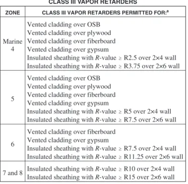
1405.3.1 Class III vapor retarders.Class III vapor retard-ers shall be permitted where any one of the conditions in Table 1405.3.1 is met.
TABLE 1405.3.1 CLASS III VAPOR RETARDERS
ZONE CLASS III VAPOR RETARDERS PERMITTED FOR:a
Marine 4
Vented cladding over OSB Vented cladding over plywood Vented cladding over fiberboard Vented cladding over gypsum
Insulated sheathing withR-value$R2.5 over 2×4 wall Insulated sheathing withR-value$R3.75 over 2×6 wall
5
Vented cladding over OSB Vented cladding over plywood Vented cladding over fiberboard Vented cladding over gypsum
Insulated sheathing withR-value$R5 over 2×4 wall Insulated sheathing withR-value$R7.5 over 2×6 wall
6
Vented cladding over fiberboard Vented cladding over gypsum
Insulated sheathing withR-value$R7.5 over 2×4 wall Insulated sheathing withR-value$R11.25 over 2×6 wall 7 and 8 Insulated sheathing withR-value$R10 over 2×4 wall
Insulated sheathing withR-value$R15 over 2×6 wall
For SI: 1 pound per cubic foot = 16.02 kg/m3.
a. Spray foam with a minimum density of 2 pounds per cubic feet applied to the interior cavity side of OSB, plywood, fiberboard, insulating sheathing or gypsum is deemed to meet the insulating sheathing requirement where the spray foamR-value meets or exceeds the specified insulating sheathing
R-value.
1405.3.2 Material vapor retarder class. The vapor retarder classshall be based on the manufacturer’s certified testing or a tested assembly.
The following shall be deemed to meet the class speci-fied:
Class I: Sheet polyethylene, nonperforated aluminum foil
Class II: Kraft-faced fiberglass batts or paint with a perm rating greater than 0.1 and less than or equal to 1.0
Class III: Latex or enamel paint
1405.3.3 Minimum clear airspaces and vented openings for vented cladding. For the purposes of this section, vented cladding shall include the following minimum clear airspaces.
1. Vinyl lap or horizontal aluminum siding applied over a weather-resistive barrier as specified in this chapter. 2. Brick veneer with a clear airspace as specified in this
code.
3. Otherapprovedvented claddings.
1405.4 Flashing.Flashing shall be installed in such a manner so as to prevent moisture from entering the wall or to redirect it to the exterior. Flashing shall be installed at the perimeters of exterior door and window assemblies, penetrations and termi-nations ofexterior wallassemblies,exterior wallintersections with roofs, chimneys, porches, decks, balconies and similar projections and at built-in gutters and similar locations where moisture could enter the wall. Flashing with projecting flanges shall be installed on both sides and the ends of copings, under sills and continuously above projectingtrim.
1405.4.1 Exterior wall pockets.In exterior walls of build-ings or structures, wall pockets or crevices in which mois-ture can accumulate shall be avoided or protected with caps or drips, or otherapprovedmeans shall be provided to pre-vent water damage.
1405.4.2 Masonry.Flashing and weep holes in anchored veneer shall be located in the first course of masonry above finished ground level above the foundation wall or slab, and other points of support, including structural floors, shelf angles and lintels where anchored veneers are designed in accordance with Section 1405.6.
1405.5 Wood veneers. Wood veneers on exterior walls of buildings of Type I, II, III and IV construction shall be not less than 1 inch (25 mm) nominal thickness, 0.438-inch (11.1 mm) exterior hardboard siding or 0.375-inch (9.5 mm) exterior-type wood structural panels or particleboard and shall conform to the following:
1. The veneer shall not exceed 40 feet (1219 mm) in height above grade. Where fire-retardant-treated wood is used, the height shall not exceed 60 feet (1829 mm) in height above grade.
2. T h e v e n e e r i s a t t a c h e d t o o r f u r r e d f r o m a noncombustible backing that is fire-resistance rated as required by other provisions of this code.
3. Where open or spaced wood veneers (without concealed spaces) are used, they shall not project more than 24 inches (610 mm) from the building wall.
1405.6 Anchored masonry veneer. Anchored masonry veneer shall comply with the provisions of Sections 1405.6, 1405.7, 1405.8 and 1405.9 and Sections 6.1 and 6.2 of TMS 402/ACI 530/ASCE 5.
1405.6.1 Tolerances.Anchored masonry veneers in accor-dance with Chapter 14 are not required to meet the toler-ances in Article 3.3 F1 of TMS 602/ACI 530.1/ASCE 6. 1405.6.2 Wind requirements. Sections 6.2.2.1 and 6.2.2.11 of TMS 402/ACI 530/ASCE 5 shall be modified as follows:
6.2.2.1Except as provided in Section 6.2.2.11, prescriptive requirements for anchored masonry veneer shall not be used in areas where the basic wind speed exceeds 130 mph (177 km/hr) as given in ASCE 7.
6.2.2.11Requirements in areas of high winds— The fol-lowing requirements apply in areas where the basic wind speed, as given in ASCE 7, exceeds 130 mph (177 km/hr) but does not exceed 150 mph (209 km/hr) and the building’s mean roof height is less than or equal to 60 ft (18.3 m):
(a) Reduce the maximum wall area supported by each anchor to 70 percent of that required in Sections 6.2.2.5.6.1 and 6.2.2.5.6.2.
(b) Space anchors at a maximum 18 in. (457 mm) hori-zontally and vertically.
(c) Provide additional anchors around openings larger than 16 inches (406 mm) in either direction. Space anchors around perimeter of opening at a maximum of 24 inches (610 mm) on center. Place anchors within 12 inches (305 mm) of openings.
1405.7 Stone veneer. Stone veneer units not exceeding 10 inches (254 mm) in thickness shall be anchored directly to masonry, concrete or to stud construction by one of the follow-ing methods:
1. With concrete or masonry backing, anchor ties shall be not less than 0.1055-inch (2.68 mm) corrosion-resistant wire, orapprovedequal, formed beyond the base of the backing. The legs of the loops shall be not less than 6 inches (152 mm) in length bent at right angles and laid in the mortar joint, and spaced so that the eyes or loops are 12 inches (305 mm) maximum on center (o.c.) in both directions. There shall be provided not less than a 0.1055-inch (2.68 mm) corrosion-resistant wire tie, or approvedequal, threaded through the exposed loops for every 2 square feet (0.2 m2) of stone veneer. This tie shall
be a loop having legs not less than 15 inches (381 mm) in length bent so that it will lie in the stone veneer mortar joint. The last 2 inches (51 mm) of each wire leg shall have a right-angle bend. One-inch (25 mm) minimum thickness of cement grout shall be placed between the backing and the stone veneer.
2. With stud backing, a 2-inch by 2-inch (51 mm by 51 mm) 0.0625-inch (1.59 mm) corrosion-resistant wire mesh with two layers ofwater-resistive barrierin accordance with Section 1404.2 shall be applied directly to wood studs spaced a maximum of 16 inches (406 mm) o.c. On studs, the mesh shall be attached with 2-inch-long (51
mm) corrosion-resistant steel wire furring nails at 4 inches (102 mm) o.c. providing a minimum 1.125-inch (29 mm) penetration into each stud and with 8d common nails at 8 inches (203 mm) o.c. into top and bottom plates or with equivalent wire ties. There shall be not less than a 0.1055-inch (2.68 mm) corrosion-resistant wire, or approvedequal, looped through the mesh for every 2 square feet (0.2 m2) of stone veneer. This tie shall be a
loop having legs not less than 15 inches (381 mm) in length, so bent that it will lie in the stone veneer mortar joint. The last 2 inches (51 mm) of each wire leg shall have a right-angle bend. One-inch (25 mm) minimum thickness of cement grout shall be placed between the backing and the stone veneer.
1405.8 Slab-type veneer.Slab-type veneer units not exceed-ing 2 inches (51 mm) in thickness shall be anchored directly to masonry, concrete or stud construction. For veneer units of marble, travertine, granite or other stone units of slab form ties of corrosion-resistant dowels in drilled holes shall be located in the middle third of the edge of the units, spaced a maximum of 24 inches (610 mm) apart around the periphery of each unit with not less than four ties per veneer unit. Units shall not exceed 20 square feet (1.9 m2) in area. If the dowels are not tight
fitting, the holes shall be drilled not more than 0.063 inch (1.6 mm) larger in diameter than the dowel, with the hole counter-sunk to a diameter and depth equal to twice the diameter of the dowel in order to provide a tight-fitting key of cement mortar at the dowel locations when the mortar in the joint has set. Veneer ties shall be corrosion-resistant metal capable of resisting, in tension or compression, a force equal to two times the weight of the attached veneer. If made of sheet metal, veneer ties shall be not smaller in area than 0.0336 by 1 inch (0.853 by 25 mm) or, if made of wire, not smaller in diameter than 0.1483-inch (3.76 mm) wire.
1405.9 Terra cotta.Anchored terra cotta or ceramic units not less than 15/
8inches (41 mm) thick shall be anchored directly to
masonry, concrete or stud construction. Tied terra cotta or ceramic veneer units shall be not less than 15/
8inches (41 mm)
thick with projecting dovetail webs on the back surface spaced approximately 8 inches (203 mm) o.c. The facing shall be tied to the backing wall with corrosion-resistant metal anchors of not less than No. 8 gage wire installed at the top of each piece in horizontal bed joints not less than 12 inches (305 mm) nor more than 18 inches (457 mm) o.c.; these anchors shall be secured to
1/
4-inch (6.4 mm) corrosion-resistant pencil rods that pass
through the vertical aligned loop anchors in the backing wall. The veneer ties shall have sufficient strength to support the full weight of the veneer in tension. The facing shall be set with not less than a 2-inch (51 mm) space from the backing wall and the space shall be filled solidly with portland cement grout and pea gravel. Immediately prior to setting, the backing wall and the facing shall be drenched with clean water and shall be dis-tinctly damp when the grout is poured.
1405.10 Adhered masonry veneer.Adhered masonry veneer shall comply with the applicable requirements of Section 1405.10.1 and Sections 6.1 and 6.3 of TMS 402/ACI 530/ASCE 5.
1405.10.1 Interior adhered masonry veneers. Interior adhered masonry veneers shall have a maximum weight of
20 psf (0.958 kg/m2) and shall be installed in accordance
with Section 1405.10. Where the interior adhered masonry veneer is supported by wood construction, the supporting members shall be designed to limit deflection to1/
600of the
span of the supporting members.
1405.11 Metal veneers.Veneers of metal shall be fabricated from approvedcorrosion-resistant materials or shall be pro-tected front and back with porcelain enamel, or otherwise be treated to render the metal resistant to corrosion. Such veneers shall not be less than 0.0149-inch (0.378 mm) nominal thick-ness sheet steel mounted on wood or metal furring strips or approved sheathing on the wood construction.
1405.11.1 Attachment. Exterior metal veneer shall be securely attached to the supporting masonry or framing members with corrosion-resistant fastenings, metal ties or by otherapproveddevices or methods. The spacing of the fastenings or ties shall not exceed 24 inches (610 mm) either vertically or horizontally, but where units exceed 4 square feet (0.4 m2) in area there shall be not less than four
attach-ments per unit. The metal attachattach-ments shall have a cross-sectional area not less than provided by W 1.7 wire. Such attachments and their supports shall be capable of resisting a horizontal force in accordance with the wind loads specified in Section 1609, but in no case less than 20 psf (0.958 kg/m2).
1405.11.2 Weather protection.Metal supports for exterior metal veneer shall be protected by painting, galvanizing or by other equivalent coating or treatment. Wood studs, fur-ring strips or other wood supports for exterior metal veneer shall be approved pressure-treated wood or protected as required in Section 1403.2. Joints and edges exposed to the weather shall be caulked withapproveddurable waterproof-ing material or by otherapprovedmeans to prevent penetra-tion of moisture.
1405.11.3 Backup.Masonry backup shall not be required for metal veneer except as is necessary to meet the fire-resis-tance requirements of this code.
1405.11.4 Grounding. Grounding of metal veneers on buildings shall comply with the requirements of Chapter 27 of this code.
1405.12 Glass veneer.The area of a single section of thin exte-rior structural glass veneer shall not exceed 10 square feet (0.93 m2) where it is not more than 15 feet (4572 mm) above the level
of the sidewalk or grade level directly below, and shall not exceed 6 square feet (0.56 m2) where it is more than 15 feet
(4572 mm) above that level.
1405.12.1 Length and height.The length or height of any section of thin exterior structural glass veneer shall not exceed 48 inches (1219 mm).
1405.12.2 Thickness.The thickness of thin exterior struc-tural glass veneer shall be not less than 0.344 inch (8.7 mm). 1405.12.3 Application. Thin exterior structural glass veneer shall be set only after backing is thoroughly dry and after application of anapprovedbond coat uniformly over the entire surface of the backing so as to effectively seal the surface. Glass shall be set in place with anapprovedmastic cement in sufficient quantity so that at least 50 percent of the
area of each glass unit is directly bonded to the backing by mastic not less than1/
4inch (6.4 mm) thick and not more
than5/
8inch (15.9 mm) thick. The bond coat and mastic shall
be evaluated for compatibility and shall bond firmly together.
1405.12.4 Installation at sidewalk level. Where glass extends to a sidewalk surface, each section shall rest in an approvedmetal molding, and be set at least1/
4inch (6.4 mm)
above the highest point of the sidewalk. The space between the molding and the sidewalk shall be thoroughly caulked and made water tight.
1405.12.4.1 Installation above sidewalk level.Where thin exterior structural glass veneer is installed above the level of the top of a bulkhead facing, or at a level more than 36 inches (914 mm) above the sidewalk level, the mastic cement binding shall be supplemented with approvednonferrous metal shelf angles located in the horizontal joints in every course. Such shelf angles shall be not less than 0.0478-inch (1.2 mm) thick and not less than 2 inches (51 mm) long and shall be spaced at approvedintervals, with not less than two angles for each glass unit. Shelf angles shall be secured to the wall or backing with expansion bolts, toggle bolts or by other approvedmethods.
1405.12.5 Joints.Unless otherwise specificallyapproved by thebuilding official, abutting edges of thin exterior struc-tural glass veneer shall be ground square. Mitered joints shall not be used except where specificallyapprovedfor wide angles. Joints shall be uniformly buttered with an approvedjointing compound and horizontal joints shall be held to not less than 0.063 inch (1.6 mm) by anapproved nonrigid substance or device. Where thin exterior structural glass veneer abuts nonresilient material at sides or top, expansion joints not less than1/
4inch (6.4 mm) wide shall be
provided.
1405.12.6 Mechanical fastenings.Thin exterior structural glass veneer installed above the level of the heads of show windows and veneer installed more than 12 feet (3658 mm) above sidewalk level shall, in addition to the mastic cement and shelf angles, be held in place by the use of fastenings at each vertical or horizontal edge, or at the four corners of each glass unit. Fastenings shall be secured to the wall or backing with expansion bolts, toggle bolts or by other meth-ods. Fastenings shall be so designed as to hold the glass veneer in a vertical plane independent of the mastic cement. Shelf angles providing both support and fastenings shall be permitted.
1405.12.7 Flashing.Exposed edges of thin exterior struc-tural glass veneer shall be flashed with overlapping corro-sion-resistant metal flashing and caulked with a waterproof compound in a manner to effectively prevent the entrance of moisture between the glass veneer and the backing. 1405.13 Exterior windows and doors.Windows and doors installed in exterior walls shall conform to the testing and per-formance requirements of Section 1715.5.
1405.13.1 Installation. Windows and doors shall be installed in accordance with approved manufacturer’s
instructions. Fastener size and spacing shall be provided in such instructions and shall be calculated based on maximum loads and spacing used in the tests.
1405.13.2 Window sills.In Occupancy Groups R-2 and R-3, one- and two-family and multiple-family dwellings, where the opening of the sill portion of an operable window is located more than 72 inches (1829 mm) above the fin-ished grade or other surface below, the lowest part of the clear opening of the window shall be at a height not less than 24 inches (610 mm) above the finished floor surface of the room in which the window is located. Glazing between the floor and a height of 24 inches (610 mm) shall be fixed or have openings through which a 4-inch (102 mm) diameter sphere cannot pass.
Exception: Openings that are provided with window guards that comply with ASTM F 2006 or F 2090. 1405.14 Vinyl siding.Vinyl siding conforming to the require-ments of this section and complying with ASTM D 3679, and ASTM D 4477 in accordance with the manufacturer’s installa-tion instrucinstalla-tions shall be permitted on exterior walls of build-ings located in areas where the Vasd as determined in
accordance with Section 1609.3.1 does not exceed 100 miles per hour (45 m/s) and thebuilding heightis less than or equal to 40 feet (12 192 mm) in Exposure C. Where construction is located in areas where the Vasdas determined in accordance
with Section 1609.3.1 exceeds 100 miles per hour (45 m/s), or building heights are in excess of 40 feet (12 192 mm), tests or calculations indicating compliance with Chapter 16 shall be submitted. Vinyl siding shall be secured to the building so as to provide weather protection for the exterior walls of the build-ing.
1405.14.1 Application. The siding shall be applied over sheathing or materials listed in Section 2304.6. Siding shall be applied to conform with the water-resistive barrier requirements in Section 1403. Siding and accessories shall be installed in accordance withapproved manufacturer’s instructions. Unless otherwise specified in the approved manufacturer’s instructions, nails used to fasten the siding and accessories shall have a minimum 0.313-inch (7.9 mm) head diameter and1/
8-inch (3.18 mm) shank diameter. The
nails shall be corrosion resistant and shall be long enough to penetrate the studs or nailing strip at least3/
4inch (19 mm).
Where the siding is installed horizontally, the fastener spac-ing shall not exceed 16 inches (406 mm) horizontally and 12 inches (305 mm) vertically. Where the siding is installed vertically, the fastener spacing shall not exceed 12 inches (305 mm) horizontally and 12 inches (305 mm) vertically. 1405.15 Cement plaster.Cement plaster applied to exterior walls shall conform to the requirements specified in Chapter 25.
1405.16 Fiber-cement siding.Fiber-cement siding comply-ing with Section 1404.10 shall be permitted on exterior walls of Type I, II, III, IV and V construction for wind pressure resis-tance or wind speed exposures as indicated by the manufac-turer’s listing andlabelandapprovedinstallation instructions. Where specified, the siding shall be installed over sheathing or materialslistedin Section 2304.6 and shall be installed to
con-form to the water-resistive barrier requirements in Section 1403. Siding and accessories shall be installed in accordance withapprovedmanufacturer’s instructions. Unless otherwise specified in the approved manufacturer’s instructions, nails used to fasten the siding to wood studs shall be corrosion-resis-tant round head smooth shank and shall be long enough to pen-etrate the studs at least 1 inch (25 mm). For metal framing, all-weather screws shall be used and shall penetrate the metal framing at least three full threads.
1405.16.1 Panel siding.Fiber-cement panels shall comply with the requirements of ASTM C 1186, Type A, minimum Grade II. Panels shall be installed with the long dimension either parallel or perpendicular to framing. Vertical and hor-izontal joints shall occur over framing members and shall be sealed with caulking, covered with battens or shall be designed to comply with Section 1403.2. Panel siding shall be installed with fasteners in accordance with theapproved manufacturer’s instructions.
1405.16.2 Lap siding. Fiber-cement lap siding having a maximum width of 12 inches (305 mm) shall comply with the requirements of ASTM C 1186, Type A, minimum Grade II. Lap siding shall be lapped a minimum of 11/
4
inches (32 mm) and lap siding not having tongue-and-groove end joints shall have the ends sealed with caulking, covered with an H-section joint cover, located over a strip of flashing or shall be designed to comply with Section 1403.2. Lap siding courses shall be installed with the fas-tener heads exposed or concealed in accordance with the approvedmanufacturer’s instructions.
1405.17 Fastening.Weather boarding and wall coverings shall be securely fastened with aluminum, copper, zinc, zinc-coated or otherapprovedcorrosion-resistant fasteners in accordance with the nailing schedule in Table 2304.9.1 or theapproved manufacturer’s installation instructions. Shingles and other weather coverings shall be attached with appropriate stan-dard-shingle nails to furring strips securely nailed to studs, or with approved mechanically bonding nails, except where sheathing is of wood not less than 1-inch (25 mm) nominal thickness or of wood structural panels as specified in Table 2308.9.3(3).
SECTION 1406
COMBUSTIBLE MATERIALS ON THE EXTERIOR SIDE OF EXTERIOR WALLS
1406.1 General.Section 1406 shall apply toexterior wall cov-erings; balconies and similar projections; and bay and oriel windows constructed of combustible materials.
1406.2 Combustible exterior wall coverings. Combustible exterior wall coveringsshall comply with this section.
Exception:Plastics complying with Chapter 26.
1406.2.1 Ignition resistance. Combustible exterior wall coveringsshall be tested in accordance with NFPA 268.
Exceptions:
1 Wood or wood-based products.
2. Other combustible materials covered with an exte-rior covering other than vinyl sidings listed in Table 1405.2.
3. Aluminum having a minimum thickness of 0.019 inch (0.48 mm).
4. Exterior wall coveringsonexterior wallsof Type V construction.
1406.2.1.1 Fire separation 5 feet or less. Where installed onexterior wallshaving afire separation dis-tanceof 5 feet (1524 mm) or less, combustibleexterior wall coverings shall not exhibit sustained flaming as defined in NFPA 268.
1406.2.1.2 Fire separation greater than 5 feet.For fire separation distances greater than 5 feet (1524 mm), an assembly shall be permitted that has been exposed to a reduced level of incident radiant heat flux in accordance with the NFPA 268 test method without exhibiting sus-tained flaming. The minimumfire separation distance required for the assembly shall be determined from Table 1406.2.1.2 based on the maximum tolerable level of inci-dent radiant heat flux that does not cause sustained flam-ing of the assembly.
TABLE 1406.2.1.2
MINIMUM FIRE SEPARATION FOR COMBUSTIBLE VENEERS
FIRE SEPARATION DISTANCE (feet) TOLERABLE LEVEL INCIDENT RADIANT HEAT ENERGY(kW/m2) FIRE SEPARATION DISTANCE (feet) TOLERABLE LEVEL INCIDENT RADIANT HEAT ENERGY(kW/m2) 5 6 7 8 9 10 11 12 13 14 15 12.5 11.8 11.0 10.3 9.6 8.9 8.3 7.7 7.2 6.7 6.3 16 17 18 19 20 21 22 23 24 25 5.9 5.5 5.2 4.9 4.6 4.4 4.1 3.9 3.7 3.5
For SI: 1 foot = 304.8 mm.
1406.2.2 Type I, II, III and IV construction.On buildings of Type I, II, III and IV construction,exterior wall coverings shall be permitted to be constructed of wood in accordance with Section 1405.5, or other equivalent combustible mate-rial, complying with the following limitations:
1. Combustibleexterior wall coveringsshall not exceed 10 percent of anexterior wallsurface area where the fire separation distanceis 5 feet (1524 mm) or less.
2. Combustible architecturaltrimshall be limited to 40 feet (12 192 mm) in height above grade.
3. Combustibleexterior wall coveringsconstructed of fire-retardant-treated woodcomplying with Section 2303.2 for exterior installation shall not be limited in wall surface area where thefire separation distanceis 5 feet (1524 mm) or less and shall be permitted up to 60 feet (18 288 mm) in height above grade regardless of thefire separation distance.
1406.2.3 Location.Where combustibleexterior wall cov-eringis located along the top of exterior walls, suchtrim shall be completely backed up by theexterior walland shall not extend over or above the top ofexterior walls.
1406.2.4 Fireblocking. Where the combustible exterior wall coveringis furred from the wall and forms a solid sur-face, the distance between the back of the covering and the wall shall not exceed 15/
8inches (41 mm). Where required
by Section 717, the space thereby created shall be fireblocked.
1406.3 Balconies and similar projections. Balconies and similar projections of combustible construction other than fire-retardant-treated wood shall be fire-resistance rated in accordance with Table 601 for floor construction or shall be of Type IV construction in accordance with Section 602.4. The aggregate length shall not exceed 50 percent of the buildings perimeter on each floor.
Exceptions:
1. On buildings of Type I and II construction, three sto-ries or less abovegrade plane,fire-retardant-treated woodshall be permitted for balconies, porches, decks and exterior stairways not used as required exits. 2. Untreated wood is permitted for pickets and rails or
similar guardrail devices that are limited to 42 inches (1067 mm) in height.
3. Balconies and similar projections on buildings of Type III, IV and V construction shall be permitted to be of Type V construction, and shall not be required to have afire-resistance ratingwhere sprinkler protec-tion is extended to these areas.
4. Where sprinkler protection is extended to the balcony areas, the aggregate length of the balcony on each floor shall not be limited.
1406.4 Bay windows and oriel windows.Bay and oriel win-dows shall conform to the type of construction required for the building to which they are attached.
Exception:Fire-retardant-treated woodshall be permitted on buildings three stories or less of Type I, II, III and IV con-struction.
SECTION 1407
METAL COMPOSITE MATERIALS (MCM)
1407.1 General.The provisions of this section shall govern the materials, construction and quality of metal composite materi-als (MCM) for use asexterior wall coverings in addition to other applicable requirements of Chapters 14 and 16.
1407.1.1 Plastic core.The plastic core of the MCM shall not contain foam plastic insulation as defined in Section 2602.1.
1407.2 Exterior wall finish.MCM used asexterior wallfinish or as elements of balconies and similar projections and bay and oriel windows to provide cladding or weather resistance shall comply with Sections 1407.4 through 1407.14.
1407.3 Architectural trim and embellishments.MCM used as architecturaltrimor embellishments shall comply with Sec-tions 1407.7 through 1407.14.
1407.4 Structural design.MCM systems shall be designed and constructed to resist wind loads as required by Chapter 16 for components and cladding.
1407.5 Approval.Results ofapprovedtests or an engineering analysis shall be submitted to thebuilding official to verify compliance with the requirements of Chapter 16 for wind loads.
1407.6 Weather resistance.MCM systems shall comply with Section 1403 and shall be designed and constructed to resist wind and rain in accordance with this section and the manufac-turer’s installation instructions.
1407.7 Durability. MCM systems shall be constructed of approvedmaterials that maintain the performance characteris-tics required in Section 1407 for the duration of use.
1407.8 Fire-resistance rating.Where MCM systems are used on exterior walls required to have afire-resistance ratingin accordance with Section 705, evidence shall be submitted to thebuilding officialthat the requiredfire-resistance ratingis maintained.
Exception: MCM systems not containing foam plastic insulation, which are installed on the outer surface of a fire-resistance-ratedexterior wallin a manner such that the attachments do not penetrate through the entire exterior wallassembly, shall not be required to comply with this sec-tion.
1407.9 Surface-burning characteristics. Unless otherwise specified, MCM shall have aflame spread indexof 75 or less and a smoke-developed index of 450 or less when tested in the maximum thickness intended for use in accordance with ASTM E 84 or UL 723.
1407.10 Type I, II, III and IV construction.Where installed on buildings of Type I, II, III and IV construction, MCM sys-tems shall comply with Sections 1407.10.1 through 1407.10.4, or Section1407.11.
1407.10.1 Surface-burning characteristics. MCM shall have aflame spread indexof not more than 25 and a smoke-developed index of not more than 450 when tested as an assembly in the maximum thickness intended for use in accordance with ASTM E 84 or UL 723.
1407.10.2 Thermal barriers. MCM shall be separated from the interior of a building by anapprovedthermal bar-rier consisting of1/
2-inch (12.7 mm) gypsum wallboard or
equivalent thermal barrier material that will limit the aver-age temperature rise of the unexposed surface to not more than 250°F (121°C) after 15 minutes of fire exposure in
accordance with the standard time-temperature curve of ASTM E 119 or UL 263. The thermal barrier shall be installed in such a manner that it will remain in place for not less than 15 minutes based on a test conducted in accor-dance with UL 1715.
1407.10.3 Thermal barrier not required. The thermal barrier specified for MCM in Section 1407.10.2 is not required where:
1. The MCM system is specificallyapprovedbased on tests conducted in accordance with UL 1040 or UL 1715. Such testing shall be performed with the MCM in the maximum thickness intended for use. The MCM system shall include seams, joints and other typical details used in the installation and shall be tested in the manner intended for use.
2. The MCM is used as elements of balconies and simi-lar projections, architecturaltrimor embellishments. 1407.10.4 Full-scale tests. The MCM system shall be tested in accordance with, and comply with, the acceptance criteria of NFPA 285. Such testing shall be performed on the MCM system with the MCM in the maximum thickness intended for use.
1407.11 Alternate conditions.MCM and MCM systems shall not be required to comply with Sections 1407.10.1 through 1407.10.4 provided such systems comply with Section 1407.11.1 or 1407.11.2.
1407.11.1 Installations up to 40 feet in height.MCM shall not be installed more than 40 feet (12 190 mm) in height above grade where installed in accordance with Sections 1407.11.1.1 and 1407.11.1.2.
1407.11.1.1 Fire separation distance of 5 feet or less. Where thefire separation distanceis 5 feet (1524 mm) or less, the area of MCM shall not exceed 10 percent of the exterior wallsurface.
1407.11.1.2 Fire separation distance greater than 5 feet.Where thefire separation distanceis greater than 5 feet (1524 mm), there shall be no limit on the area of exte-rior wallsurface coverage using MCM.
1407.11.2 Installations up to 50 feet in height.MCM shall not be installed more than 50 feet (15 240 mm) in height above grade where installed in accordance with Sections 1407.11.2.1 and 1407.11.2.2.
1407.11.2.1 Self-ignition temperature. MCM shall have a self-ignition temperature of 650°F (343°C) or greater when tested in accordance with ASTM D 1929. 1407.11.2.2 Limitations. Sections of MCM shall not exceed 300 square feet (27.9 m2) in area and shall be
sep-arated by a minimum of 4 feet (1219 mm) vertically. 1407.12 Type V construction.MCM shall be permitted to be installed on buildings of Type V construction.
1407.13 Foam plastic insulation.MCM systems containing foam plastic insulation shall also comply with the requirements of Section 2603.
1407.14 Labeling.MCM shall be labeled in accordance with Section 1703.5.
SECTION 1408
EXTERIOR INSULATION AND FINISH SYSTEMS (EIFS)
1408.1 General.The provisions of this section shall govern the materials, construction and quality of exterior insulation and finish systems (EIFS) for use asexterior wall coveringsin addi-tion to other applicable requirements of Chapters 7, 14, 16, 17 and 26.
1408.2 Performance characteristics. EIFS shall be con-structed such that it meets the performance characteristics required in ASTM E 2568.
1408.3 Structural design.The underlying structural framing and substrate shall be designed and constructed to resist loads as required by Chapter 16.
1408.4 Weather resistance.EIFS shall comply with Section 1403 and shall be designed and constructed to resist wind and rain in accordance with this section and the manufacturer’s application instructions.
1408.4.1 EIFS with drainage. EIFS with drainage shall have an average minimum drainage efficiency of 90 percent when tested in accordance the requirements of ASTM E 2273 and is required on framed walls of Type V construc-tion, Group R1, R2, R3 and R4 occupancies.
1408.4.1.1 Water-resistive barrier. For EIFS with drainage, thewater-resistive barriershall comply with Section 1404.2 or ASTM E 2570.
1408.5 Installation.Installation of the EIFS and EIFS with drainage shall be in accordance with the EIFS manufacturer’s instructions.
1408.6 Special inspections.Reserved.
SECTION 1409
HIGH-VELOCITY HURRICANE ZONES OTHER MATERIALS
1409.1 Wood.
1409.1.1Wood and wood products used for wall claddings shall comply with Section 2314 through 2330.
1409.1.2Wood and wood-products used for wall cladding as non-structural exterior trim, fascia and soffits on build-ings of Type I, II-A and IV. Construction may be applied to the outside of exterior walls, cornices, architectural append-ages, eaves overhangs and similar projections.
Where an exterior wall is required to be fire resistive, such material shall be separated from the interior of the building by the vertical extension of the exterior wall. 1409.2 Asphalt shingles.Asphalt shingles shall be applied only to solid wood sheathing and shall be in tin-capped and spot-stuck, as set forth in Sections 1512 through 1525. 1409.3 Roll slate or felt.Roll slate or felt shall be applied only to solid wood sheathing and shall be secured by nailing, as set forth in Chapter 15, (High-Velocity Hurricane Zones). 1409.4 Metal shingles.Metal shingles shall be applied only to solid wood sheathing and shall be secured as set forth in Chap-ter 15 (High-Velocity Hurricane Zone).
1409.5 Steel shingles. Steel Siding shall be designed and applied as set forth in Sections 2214 through 2224.
1409.6 Aluminum siding.Aluminum siding shall be designed and applied as set forth in Section 2003.
1409.7 Veneers.Masonry veneers shall be applied as set forth in Sections 2118 through 2122.
1409.8 Combustible materials. Combustible materials and fire resistive characteristics of all materials shall comply with the requirements for the group of occupancy or type of con-struction, and the required interior finish rating.
1409.9 Other materials.Any cladding materials or assembly not addressed in this code shall be classified by the building official as the one it most nearly resembles, and shall comply with the requirements for loading and fire resistance herein required for such materials and assemblies.