ARC-1110/1120/1130/1160/1170
( 4/8/12/16/24-port PCI-X SATA RAID Controllers )
ARC-1110ML/1120ML/1130ML/1160ML
( 4/8/12/16-port PCI-X SATA RAID Controllers )
ARC-1210/1220/1230/1260
( 4/8/12/16-port PCI-Express SATA RAID Controllers )
SATA RAID Cards
Copyright Statement
Areca Technology Corporation
© COPYRIGHT 2005
ALL RIGHTS RESERVED. First Edition.
All trademarks are the properties of their respective owners. No por-tion of this document may be reproduced, altered, adapted or
trans-USER Manual
Version: 2.10
Microsoft WHQL Windows Hardware Compatibility
Test
ARECA is committed to submit to Microsoft Windows Hardware Quality Labs (WHQL) for participation in the Windows Logo Program. Successful passage of the WHQL tests results in both the “Designed for Windows” logo for qualifying ARECA PCI-X or PCI-Express SATA RAID controllers and a listing on the Microsoft Hardware Compatibility List (HCL).
WARRANTY
The information in this document is subject to change without notice. We make no warranty of any kind regarding this material, including, but not limited to, the implied warranties or merchantability and fitness for a particular purpose. Furthermore, we shall not be liable for errors con-tained herein or for incidental or consequential damage in connection with the furnishing, performance, or use of this material.
FCC STATEMENT
This equipment has been tested and found to comply with the limits for a Class B digital device, pursuant to part 15 of the FCC Rules. These limits are designed to provide reasonable protection against interfer-ence in a residential installation. This equipment generates, uses, and can radiate radio frequency energy and, if not installed and used in ac-cordance with the instructions, may cause harmful interference to radio communications. However, there is no guarantee that interference will not occur in a particular installation.
Contents
1. Introduction ... 8 1.1 Overview ...8 1.2 Features ... 10 1.3 RAID Concept ... 12 1.3.1 RAID Set ... 12 1.3.2 Volume Set ... 121.3.3 Easy of Use Features ... 13
1.3.3.1 Instant Availability/Background Initialization ... 13
1.3.3.2 Array Roaming ... 13
1.3.3.3 Online Capacity Expansion ... 14
1.3.4 Online RAID Level and Stripe Size Migration ... 15
1.4 High availability ... 15
1.4.1 Creating Hot Spares ... 15
1.4.2 Hot-Swap Disk Drive Support ... 16
1.4.3 Hot-Swap Disk Rebuild ... 16
1.5 Understanding RAID ... 16 1.5.1 RAID 0 ... 17 1.5.2 RAID 1 ... 17 1.5.3 RAID 10 ... 18 1.5.4 RAID 3 ... 18 1.5.5 RAID 5 ... 19 1.5.6 RAID 6 ... 19 2. Hardware Installation ... 22
2.1 Before Your begin Installation ... 22
2.2 Board Layout ... 23
2.3 Installation ... 27
3. McBIOS RAID Manager ... 38
3.1 Starting the McBIOS RAID Manager ... 38
3.2 McBIOS Configuration manager ... 39
3.3 Configuring Raid Sets and Volume Sets ... 40
3.4 Designating Drives as Hot Spares ... 40
3.5 Using Quick Volume /Raid Setup Configuration ... 41
3.6 Using Raid Set/Volume Set Function Method ... 42
3.7 Main Menu ... 44
3.7.1 Quick Volume/RAID Setup ... 45
3.7.2 Raid Set Function ... 47
3.7.2.2 Delete Raid Set ... 49
3.7.2.3 Expand Raid Set ... 49
• Migrating ... 50
3.7.2.4 Activate Incomplete Raid Set ... 51
3.7.2.5 Create Hot Spare ... 52
3.7.2.6 Delete Hot Spare ... 52
3.7.2.7 Raid Set Information ... 53
3.7.3 Volume Set Function ... 53
3.7.3.1 Create Volume Set ... 54
• Volume Name ... 56 • Raid Level ... 56 • Capacity ... 57 • Strip Size ... 57 • SCSI Channel ... 58 • SCSI ID ... 58 • SCSI LUN ... 59 • Cache Mode ... 59 • Tag Queuing ... 59
3.7.3.2 Delete Volume Set ... 60
3.7.3.3 Modify Volume Set ... 61
• Volume Growth ... 62
• Volume Set Migration ... 62
3.7.3.4 Check Volume Set ... 63
3.7.3.5 Stop Volume Set Check ... 63
3.7.3.6 Display Volume Set Info. ... 64
3.7.4 Physical Drives ... 65
3.7.4.1 View Drive Information ... 65
3.7.4.2 Create Pass-Through Disk ... 66
3.7.4.3 Modify Pass-Through Disk ... 66
3.7.4.4 Delete Pass-Through Disk ... 67
3.7.4.5 Identify Selected Drive ... 67
3.7.5 Raid System Function ... 68
3.7.5.1 Mute The Alert Beeper ... 68
3.7.5.2 Alert Beeper Setting ... 69
3.7.5.3 Change Password ... 69
3.7.5.4 JBOD/RAID Function ... 70
3.7.5.5 Background Task Priority ... 71
3.7.5.6 Maximum SATA Mode ... 71
3.7.5.7 Disk Write Cache Mode ... 72
3.7.5.8 Capacity Truncation ... 72
3.7.5.9 Controller Fan Detection ... 73
3.7.6 Ethernet Configuration (12/16/24 ports) ... 74
3.7.6.1 DHCP Function ... 75
3.7.6.2 Local IP address ... 75
3.7.6.3 Ethernet Address ... 76
3.7.7 View System Events ... 77
3.7.8 Clear Events Buffer ... 77
3.7.9 Hardware Monitor ... 77
3.7.10 System Information ... 78
4. Driver Installation ... 79
4.1 Creating the Driver Diskettes ... 79
4.2 Driver Installation for Windows ... 80
4.2.1 New Storage Device Drivers in Windows Server 2003 ... 80
4.2.2 Install Windows 2000/XP/2003 on a SATA RAID Volume .. 81
4.2.2.1 Installation procedures ... 81
4.2.2.2 Making Volume Sets Available to Windows System ... 82
4.2.3 Install controller into an existing Windows 2000/XP/2003 83 4.2.3.1 Making Volume Sets Available to Windows System ... 84
4.2.4 Uninstall controller from Windows 2000/XP/2003 ... 85
4.3 Driver Installation for Linux ... 86
4.4 Driver Installation for FreeBSD ... 86
5. Installation ArcHttp Proxy Server ... 88
5.1 For Windows ... 88
5.2 For Linux ... 89
6. Web Browser-based Configuration ... 91
6.1 Start-up McRAID Manager for Local Administration ... 91
6.1.1 For Windows ... 92
6.1.2 For Linux ... 94
6.2 Start-up McRAID Manager for Remote Administration ... 94
6.2.1 Microsoft Windows System ... 94
6.2.2 Linux System ... 95
6.3 SATA RAID controller McRAID storage manager ... 95
6.4 Main Menu ... 96
6.5 Quick Function ... 97
6.6 RaidSet Functions ... 98
6.6.1 Create Raid Set ... 98
6.6.2 Delete Raid Set ... 98
6.6.3 Expand Raid Set ... 99
6.6.4 Activate Incomplete Raid Set ... 99
6.6.5 Create Hot Spare ... 100
6.6.6 Delete Hot Spare ... 101
6.7 Volume Set Functions ... 101
6.7.1 Create Volume Set ... 102
• Volume Name ... 102
• Capacity ... 102
• Raid Level ... 102
• Strip Size ... 103
• Cache Mode ... 103
• SCSI Channel/SCSI ID/SCSI Lun ... 103
• Tag Queuing ... 103
6.7.2 Delete Volume Set ... 103
6.7.3 Modify Volume Set ... 104
6.7.3.1 Volume Set Migration ... 105
6.7.4 Check Volume Set ... 105
6.7.5 Stop VolumeSet Check ... 106
6.8 Physical Drive ... 106
6.8.1 Create Pass-Through Disk ... 106
6.8.2 Modify Pass-Through Disk ... 107
6.8.3 Delete Pass-Through Disk ... 108
6.8.4 Identify Selected Drive ... 108
6.9 System Controls ... 109
6.9.1 System Config ... 109
• System Beeper Setting ... 109
• Background Task Priority ... 109
• JBOD/RAID Configuration ... 109
6.9.2 Ethernet Configuration (12/16/24 ports) ... 110
6.9.3 Alert by Mail Configuration (12/16/24 ports) ... 111
6.9.4 SNMP Configuration ... 112
6.9.5 View Events/Mute Beeper ... 113
6.9.6 Generate Test Event ... 113
6.9.7 Clear Events Buffer ... 113
6.9.8 Modify Password ... 114 6.9.9 Update Firmware ... 115 6.10 Information ... 115 6.10.1 RaidSet Hierarchy ... 115 6.10.2 System Information ... 115 6.10.3 Hardware Monitor ... 116 Appendix A ... 117
Upgrading Firmware Through McRAID Storage Manager ... 117
Appendix B ... 119
Battery Backup Module (BBM) ... 119
BBM Specifications ... 119
Installation ... 120
Battery Backup Capacity ... 120
Operation ... 120
Changing the Battery Backup Module ... 121
Appendix C ... 122
SNMP Operation & Definition ... 122
Appendix D ... 125
General Troubleshooting Tips ... 125
Appendix E ... 129 Technical Support ... 129 Glossary ... 130 2TB ... 130 Array ... 130 ATA ... 130
Auto Reassign Sector ... 130
Battery Backup Module ... 131
BIOS ... 131
Cache ... 131
Consistency Check ... 131
Driver ... 131
Hot Spare ... 132
Hardware RAID versus Software RAID ... 132
Hot Swap ... 132 NVRAM ... 132 Parity ... 132 PCI Express ... 132 PCI-X ... 133 RAID ... 133 Rebuild ... 133
SATA (Serial ATA) ... 133
SMART ... 134 SNMP ... 134 Volume Set ... 134 Write-back ... 134 Write-through ... 134 XOR-Engine ... 135
INTRODUCTION
1. Introduction
This section briefly describes general overview of SATA RAID Series controller card, ARC-1110/1120/1130/1160/1170 (4/8/12/16/24-port PCI-X SATA RAID Controller) and ARC-1210/1220/1230/1260/1270 (4/8/12/16/24-port PCI-Express SATA RAID Controller).
1.1 Overview
ARC-11xx/12xx Series high-performance PCI bus Card Serial ATA RAID controller supported 4, 8, 12, 16, 24 SATA-II peripheral de-vice on a single controller. With properly configured, SATA controller can provided non-stop services with a high degree of fault tolerance through the use of RAID technology and advanced array manage-ment features. The 4/8 port SATA RAID controller is a low-profile PCI cards-Ideal for 1U or 2U rack-mount system. It has the same RAID kernel of its field-proven external RAID controller. Lets bring quickly to stable and reliable RAID controller to the market.
Unparalleled Performance
The array controllers provide reliable data protection for desktops, workstations and servers. They raise the standard higher perfor-mance levels with several enhancements including Intel high-perfor-mance I/O Processor, a new DDR memory architecture (DDR333) and high performance PCI bus interconnection. SATA RAID 8/12/16/24-port controller with Areca RAID 6 engine buid-in can offer extreme performance RAID 6 function. It can concurrently compute two par-ity blocks and performance very similar to RAID 5. The controllers default support 128MB ECC DDR333 SDRAM memory. The 12/16/24 ports controllers support one SODIMM socket for upgrading up to 1GB. The controllers use the Marvell 4/8 channels SATA PCI-X con-troller chip, which can simultaneously communicate with the host system, and read or write data on several drives.
Unsurpassed Data Availability
As storage capacities continue to rapidly increase, user needs greater level of disk drive fault tolerance, which can be implemented without
INTRODUCTION
doubling the investment in disk drives. RAID 1 can provide greater fault tolerance, but needs double disk drives and is too costly for most users to implement on large volume sets. User wants protec-tion of RAID 1 or better with an implementaprotec-tion cost comparable to RAID 5. The RAID 6 can offer fault tolerance greater that RAID 1 or RAID 5 but only consumes capacity of 2 disk drives for distributed parity data. The 8/12/16/24-port RAID controllers provide the high-est RAID 6 feature to meet above requirements.
The 4/8/12/16/24-port controllers also provide RAID levels 0, 1, (10), 3, 5, and JBOD RAID configurations. Its high data availability and protection derives from the following capabilities: Online RAID Capacity Expansion, Array Roaming, Online RAID Level / Stripe Size Migration, Dynamic Volume Set Expansion, Global Online Spare, Au-tomatic Drive Failure Detection, AuAu-tomatic Failed Drive Rebuilding, Disk Hot-Swap, Online Background Rebuilding and Instant Availabil-ity/Background Initialization.
During the controller firmware upgrade flash process, it is possible for a problem to occur resulting in corruption of the controller firm-ware. With our Redundant Flash image feature the controller will revert back to the last known version of firmware and continue oper-ating. This reduces the risk of system failure due to firmware crash.
Easy RAID Management
SATA RAID controller build-in firmware with an embedded terminal emulation that can access via hot key at BIOS boot-up screen. This pre-boot manager utility can use to simplify the setup and manage-ment of RAID controller. The controller firmware also contains HTTP browser-based program that can access through the drive ArcHttp Proxy Server function in Windows, Linux and FreeBSD environment. The Web browser-based RAID management allows local and remote to create and modify RAID set, volume set, and monitor RAID status from standard web browser.
INTRODUCTION
1.2 Features
Adapter Architecture• Intel IOP 80331 I/O processor (ARC-11xx series)
• Intel IOP 80332/IOP80333 I/O processor (ARC-12xx series) • 64-bit/133MHz PCI-X Bus compatible
• PCI Express X8 compatible
• 128MB DDR333 SDRAM with ECC protection
• One SO-DIMM Socket support DDR333 SDRAM with ECC protection, upgrade to 1GB
• An ECC or non-ECC SDRAM module using X8 or X16 devices • Support up to 4/8/12/16/24 SATA ll drives
• Write-through or write-back cache support
• Multi-adapter support for large storage requirements • BIOS boot support for greater fault tolerance
• BIOS PnP (plug and play) and BBS (BIOS boot specification) support
• Areca or Intel R6 supports extreme performance RAID 6 function • NVRAM for RAID event & transaction log
• Battery backup module (BBM) ready (Depend on M/B)
RAID Features
• RAID level 0, 1, (10), 3, 5, 6 (R6 engine inside) and JBOD • Multiple RAID selection
• Online Array roaming
• Online RAID level/stripe size migration
• Online capacity expansion volume growth and RAID level migration simultaneously
• Instant availability and background initialization
• Automatic drive insertion / removal detection and rebuilding • Greater than 2TB per volume set for 64-bit LBA
• Redundant flash image for adapter availability
• Support S.M.A.R.T. NCQ and OOB Staggered Spin-up Capable drives
Monitors/Notification
• System status indication through LED/LCD connector, HDD activity/fault connector, and alarm buzzer
• SMTP support for email notification • SNMP support for remote notification • I2C Enclosure Management Ready
INTRODUCTION
RAID Management
• Field-upgradeable firmware in flash ROM • Ethernet port support on 12/16/24-port
In-Band Manager
• Hot key boot-up McBIOS RAID manager via BIOS
• Support controller’s API library for customer to write its own AP • Support Command Line Interface (CLI)
• Browser-based management utility via ArcHttp Proxy Server • Single Admin Portal (SAP) monitor utility
• Disk Stress Test (DST) utility for production in Windows
Out-of-Band Manager
• Firmware-embedded Browser-based RAID manager, SMTP manager, SNMP agent, and Telnet function via Ethernet port (for 12/16/24 port Adapter)
• Support controller’s API library for customer to write its own AP(for 12/16/24 port Adapter)
• Push Button and LCD display panel
Operating System
• Windows 2000/XP/Server 2003 • Red Hat Linux
• SuSE Linux • FreeBSD
(For latest supported OS listing visit http://www.areca.com.tw)
Internal PCI-X RAID Card Comparison (ARC-XXXX)
1110 1120 1130 1160 1170
Host Bus Type PCI-X 133MHz
RAID 6 support N/A YES YES YES YES
Cache Memory 128MB 128MB One
SO-DIMM One SO-DIMM One SO-DIMM Drive Support 4 * SATA ll 8 * SATA ll 12 * SATA ll 16 * SATA ll 24 * SATA ll
INTRODUCTION
1.3 RAID Concept
1.3.1 RAID Set
A Raid Set is a group of disk containing one or more volume sets. It has the following features in the SATA RAID controller. A volume Set must be created either on an existing raid set or on a group of available individual disks (disks that are not yet a part of an raid set). If there are pre-existing raid sets with available capacity and enough disks for specified RAID level desired, then the volume set will be created in the existing raid set of the user’s choice. If physical disk of different capacity are grouped together in a raid set, then the capacity of the smallest disk will become the effective capacity of all the disks in the raid set.
1.3.2 Volume Set
A Volume Set is seen by the host system as a single logical device. It is organized in a RAID level with one or more physical disks. RAID level refers to the level of data performance and protection of a Volume Set. A Volume Set capacity can consume all or a portion
Internal PCI-Express RAID Card Comparison (ARC-XXXX)
1210 1220 1230 1260
Host Bus Type PCI-Express X8
RAID 6 support N/A YES YES YES
Cache Memory 128MB 128MB One SODIMM One SODIMM Drive Support 4 * SATA ll 8 * SATA ll 12 * SATA ll 16 * SATA ll
Disk Connector SATA SATA SATA SATA
Internal PCI-X RAID Card Comparison (ARC-XXXXML)
1110ML 1120ML 1130ML 1160ML
Host Bus Type PCI-X 133MHz
RAID 6 support N/A YES YES YES
Cache Memory 128MB 128MB One SODIMM One SODIMM Drive Support 4 * SATA ll 8 * SATA ll 12 * SATA ll 16 * SATA ll Disk Connector SATA/Multi-lane SATA/Multi-lane SATA/Multi-lane SATA/Multi-lane
INTRODUCTION
of disk capacity available in a RAID Set. Multiple Volume Sets can exist on a group of disks in a Raid Set.
In the illustration below, Volume 1 can be assigned a RAID 5 level of operation while Volume 0 might be assigned a RAID (10) level of operation.
1.3.3 Easy of Use Features
1.3.3.1 Instant Availability/Background Initializa-tion
RAID 0 and RAID 1 volume set can be used immediately after the creation. But the RAID 3 and 5 volume sets must be initialized to generate the parity. In the Normal Initialization, the initialization proceeds as a background task, the volume set is fully accessible for system reads and writes. The operating system can instantly access to the newly created arrays without requiring a reboot and waiting the initialization complete. Furthermore, the RAID volume set is also protected against a single disk failure while initialing. In Fast Initialization, the initialization proceeds must be complet-ed before the volume set ready for system accesses.
1.3.3.2 Array Roaming
The SATA RAID controller stores configuration information both in NVRAM and on the disk drives It can protect the configuration set-tings in the case of a disk drive or controller failure. Array roam-ing allows the administrators the ability to move a completely raid set to another system without losing RAID configuration and data on that raid set. If a server fails to work, the raid set disk drives
INTRODUCTION
1.3.3.3 Online Capacity Expansion
Online Capacity Expansion makes it possible to add one or more physical drive to a volume set, while the server is in operation, eliminating the need to store and restore after reconfigured the raid set. When disks are added to a raid set, unused capacity is added to the end of the raid set. Data on the existing volume sets residing on that raid set is redistributed evenly across all the disks. A contiguous block of unused capacity is made available on the raid set. The unused capacity can create additional volume set. The expansion process is illustrated as following figure.
The SATA RAID controller redistributes the original volume set over the original and newly added disks, using the same fault-tolerance configuration. The unused capacity on the expand raid set can then be used to create an additional volume sets, with a different fault tolerance setting if user need to change.
INTRODUCTION
1.3.4 Online RAID Level and Stripe Size
Migra-tion
User can migrate both the RAID level and stripe size of an existing volume set, while the server is online and the volume set is in use. Online RAID level/stripe size migration can prove helpful during performance tuning activities as well as in the event that additional physical disks are added to the SATA RAID controller. For example, in a system using two drives in RAID level 1, you could add capac-ity and retain fault tolerance by adding one drive. With the addi-tion of third disk, you have the opaddi-tion of adding this disk to your existing RAID logical drive and migrating from RAID level 1 to 5. The result would be parity fault tolerance and double the available capacity without taking the system off.
1.4 High availability
1.4.1 Creating Hot Spares
A hot spare drive is an unused online available drive, which is ready for replacing the failure disk drive. In a RAID level 1, (10), 3, or 5 raid set, any unused online available drive installed but not belong-ing to a raid set can define as a hot spare drive. Hot spares permit you to replace failed drives without powering down the system. When SATA RAID controller detects a SATA drive failure, the system will automatic and transparent rebuilds using hot spare drives. The raid set will be reconfigured and rebuilt in the background, while the SATA RAID controller continues to handle system request. Dur-ing the automatic rebuild process, system activity will continue as normal, however, the system performance and fault tolerance will be affected.
Important
:
The hot spare must have at least the same capacity as the drive it replaces.
INTRODUCTION
1.4.2 Hot-Swap Disk Drive Support
The SATA RAID controller has built the protection circuit to sup-port the replacement of SATA hard disk drives without having to shut down or reboot the system. The removable hard drive tray can deliver “hot swappable,” fault-tolerant RAID solutions at prices much less than the cost of conventional SCSI hard disk SATA RAID controllers. We provide this feature for controllers to provide the advanced fault tolerant RAID protection and “online” drive replace-ment.
1.4.3 Hot-Swap Disk Rebuild
A Hot-Swap function can be used to rebuild disk drives in arrays with data redundancy such as RAID level 1, (10), 3, and 5. If a hot spare is not available, the failed disk drive must be replaced with a new disk drive so that the data on the failed drive can be rebuilt. If a hot spare is available, the rebuild starts automatically when a drive fails. The SATA RAID controller automatically and transpar-ently rebuilds failed drives in the background with user-definable rebuild rates. The SATA RAID controller will automatically restart the system and the rebuild if the system is shut down or powered off abnormally during a reconstruction procedure condition. When a disk is Hot Swap, although the system is functionally operational, the system may no longer be fault tolerant. Fault tolerance will be lost until the removed drive is replaced and the rebuild operation is completed.
1.5 Understanding RAID
RAID is an acronym for Redundant Array of Independent Disks. It is an array of multiple independent hard disk drives that provide high performance and fault tolerance. The SATA RAID controller imple-ments several levels of the Berkeley RAID technology. An appropri-ate RAID level is selected when the volume sets are defined or cre-ated. This decision is based on disk capacity, data availability (fault tolerance or redundancy), and disk performance. The following is the RAID level, which support in the SATA RAID controller.
The SATA RAID controller makes the RAID implementation and the disks’ physical configuration transparent to the host operating sys-tem. This means that the host operating system drivers and software
INTRODUCTION
utilities are not affected, regardless of the RAID level selected. Cor-rect installation of the disk array and the controller requires a proper understanding of RAID technology and the concepts.
1.5.1 RAID 0
RAID 0, also referred to as striping, writes stripping of data across multiple disk drives instead of just one disk drive. RAID 0 does not provide any data redundancy, but does offer the best high-speed data throughput. RAID 0 breaks up data into smaller blocks and then writes a block to each drive in the array. Disk striping en-hances performance because multiple drives are accessed simul-taneously; but the reliability of RAID Level 0 is less than any of its member disk drives due to its lack of redundancy.
1.5.2 RAID 1
RAID 1 also known as “disk mirroring”, data written to one disk drive is simultaneously written to another disk drive. Read performance may be enhanced if the array controller can parallel accesses both members of a mirrored pair. During writes, there will be a minor performance penalty when compared to writing to a single disk. If one drive fails, all data (and software applications) are preserved on the other drive. RAID 1 offers extremely high data reliability, but at the cost of doubling the required data storage capacity.
INTRODUCTION
1.5.3 RAID 10
RAID 10 is a combination of RAID 0 and RAID 1, combing stripping with disk mirroring. RAID Level 10 combines the fast performance of Level 0 with the data redundancy of Level 1. In this configura-tion, data is distributed across several disk drives, similar to Level 0, which are a stripe across a number of mirrored sets for data protection. RAID 10 provides the highest read/write performance of any of the Hybrid RAID levels, but at the cost of doubling the required data storage capacity.
1.5.4 RAID 3
RAID 3 provides disk striping and complete data redundancy though a dedicated parity drive. RAID 3 breaks up data into smaller blocks, calculates parity by performing an exclusive-or on the blocks, and then writes the blocks to all but one drive in the array. The parity data created during the exclusive-or is then written to the last drive in the array. If a single drive fails, data is still available by
com-INTRODUCTION
puting the exclusive-or of the contents corresponding strips of the surviving member disk. RAID-3 is best for applications that require very fast data- transfer rates or long data blocks.
1.5.5 RAID 5
RAID 5 is sometimes called striping with parity at byte level. In RAID 5, the parity information is written to all of the drives in the controllers rather than concentrated on a dedicated parity disk. If one drive in the system fails, the parity information can be used to reconstruct the data from that drive. All drives in the array system can be used to seek operation at the same time, greatly increasing the performance of the RAID system This relieves the write bottle-neck that characterizes RAID 4, and is the primary reason that RAID 5 is more often implemented in RAID arrays.
1.5.6 RAID 6
RAID 6 provides highest reliability, but not widely used. Similar to RAID 5, but does two different parity computations or the same
INTRODUCTION
computation on overlapping subsets of the data. The RAID 6 can offer fault tolerance greater that RAID 1 or RAID 5 but only con-sumes the capacity of 2 disk drives for distributed parity data. RAID 6 is an extension of RAID 5 that uses a second independent distributed parity scheme. Data is striped on a block level across a set of drives, and then a second set of parity is calculated and writ-ten across all of the drives.
INTRODUCTION
Summary of RAID Levels
SATA RAID controller supports RAID Levels 0, 1, (10), 3, 5 and 6. Table below provides a summary of RAID levels.
Features and Performance
RAID
Level Description Min. Drives Data Reliability Data Transfer Rate
I/O Request Rates 0 Also known as stripping
Data distributed across multiple drives in the array. There is no data protection
1 No data
Protection Very High Very High forBoth Reads and Writes 1 Also known as mirroring
All data replicated on N
Separated disks. N is almost always 2. This is a high availability
Solution, but due to the 100% duplication, it is also a costly solution.
2 Lower than RAID 6; Higher than RAID 3,5 Reads are higher Than a single disk; Writes similar to a single disk
Reads are twice faster than a single disk; Write are similar to a single disk.
10 Also known Block-Interleaved Parity. Data and parity information is subdivided and distributed across all disk. Parity must be the equal to the smallest disk capacity in the array. Parity information normally stored on a dedicated parity disk.
3 Lower than RAID 6; Higher than RAID 3,5 Transfer rates more similar to RAID 1 than RAID 0
Reads are twice faster than a single disk; Writes are similar to a single disk.
3 Also known Bit-Interleaved Parity. Data and parity information is subdivided and distributed across all disk. Parity must be the equal to the smallest disk capacity in the array. Parity information normally stored on a dedicated parity disk.
3 Lower than RAID 1, (10), 6; Higher than a single drive Reads are similar to RAID 0; Writes are slower than a single disk
Reads are similar twice faster than a single disk;
Writes are similar to a single disk.
5 Also known Block-Interleaved Distributed Parity.
Data and parity information is subdivided and distributed across all disk. Parity must be the equal to the smallest disk capacity in the array. Parity information normally stored on a dedicated parity disk.
3 Lower than RAID 1, (10), 6; Higher than a single drive Reads are similar to RAID 0; Writes are slower than a single disk
Reads are similar to RAID 0;
Writes are slower than a single disk.
6 RAID 6 provides highest reliability, but not widely used. Similar to RAID 5, but does two different parity computations or the same computation on overlapping subsets of the data. The RAID 6 can offer fault tol-erance greater that RAID 1 or RAID 5 but only consumes the capacity of 2 disk drives for distributed parity data.
4 highest reliability
HARDWARE INSTALLATION
2. Hardware Installation
This section describes the procedures for installing ARC-11xx/12xx se-ries.
2.1 Before Your begin Installation
Thanks for purchase SATA RAID Controller as your RAID data storage and management system. This user guide gives simple and step-by-step instructions for installing and configuring your SATA RAID Con-troller. To ensure your personal safety and protect your equipment and data, carefully read the information that follows the package content list before you begin installing.
Package Contents
If your package is missing any of the items listed below, contact
your local dealer before proceeding with installation (disk drives
and disk mounting brackets are not included): ARC-11xx Series SATA RAID Controller
• 1 x PCI-X SATA RAID Controller in an ESD-protective bag • 4/8/12/16/24 x SATA interface cables (one per port) • 1 x CD
• 1 x User Manual
ARC-11xxML Series SATA RAID Controller
• 1 x PCI-X SATA RAID Controller in an ESD-protective bag • 1 x CD
• 1 x User Manual
ARC-12xx Series SATA RAID Controller
• 1 x PCI-Express SATA RAID Controller in an ESD-protective bag • 4/8/12/16/24 x SATA interface cables (one per port)
• 1 x Installation CD • 1 x User Manual
HARDWARE INSTALLATION
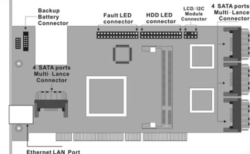
2.2 Board Layout
Follow the instruction below to install a PCI RAID Card into your PC/ Server.
Figure 2-1 ARC-1110/1120 (4/8-port PCI-X SATA RAID Controller)
Figure 2-2 ARC-1210/1220 (4/8-port PCI-Express SATA RAID Con-troller)
HARDWARE INSTALLATION
Figure 2-3 ARC-1100ML/1120ML (4/8-port PCI-X SATA RAID Con-troller)
Figure 2-4 ARC-1130/1160 (12/16-port PCI-X SATA RAID Control-ler)
HARDWARE INSTALLATION
Figure 2-5 ARC-1130ML/1160ML (12/16-port PCI-X SATA RAID Controller)
Figure 2-6 ARC-1230/1260 (12/16-port PCI-EXpress SATA RAID Controller)
HARDWARE INSTALLATION
Figure 2-5 ARC-1170 (24-port PCI-X SATA RAID Controller)
Tools Required
An ESD grounding strap or mat Standard hand tools to open your system’s case and install the SATA RAID Controller into an available PCI expansion slot.
System Requirement
The controller can be installed in a universal PCI slot and requires a motherboard that:
ARC-11xx series
• Complies with the PCI Revision 2.3 32/64-bit 33/66MHz, 3.3V. • Complies with the PCI-X 32/64-bit 66/100/133 MHz, 3.3V. ARC-12xx series
• Complies with the PCI-Express X8
• The SATA RAID controller may be connected to up to 4, 8, 12, 16, and 24 SATA ll hard drives by the supplied cables.
• An optional cables to connect the drive activity LED and fault LED on the enclosure to the PCI SATA RAID controller.
Installation Tools
HARDWARE INSTALLATION
SATA RAID adapter into an available PCI expansion slot. • Small screwdriver
• Host system hardware manuals and manuals for disk or enclo-sure being installed.
Personal Safety Information
To ensure you personal safety, as well as the safety of your equip-ment:
• Always wear a grounded strap or work on an ESD-protective mat.
• Before opening the system cabinet, turn off power switches and unplug the power cords. Do no reconnect the power cords until you have replaced the covers.
Warning:
High voltages may be found inside computer equipment. Before install-ing any of the hardware in this package or removinstall-ing the protective cov-ers of any computer equipment, turn off power switches and disconnect power cords. Do not reconnect the power cords until you have replaced the covers.
Electrostatic Discharge
Static electricity can be a serious danger to the electronic com-ponents on this SATA RAID adapter. To avoid damage caused by electrostatic discharge, observe the following precautions:
• Don’t remove the SATA RAID controller from its anti-static pack-aging until you are ready to install it into a computer case.
• Handle the SATA RAID Controller by its edges or by the mounting metal bracket at its two ends.
• Before you handle the SATA RAID controller in any way, touch a grounded, anti-static surface, such as an unpainted portion of the system chassis, for a few seconds to discharge any built-up static electricity.
2.3 Installation
HARDWARE INSTALLATION
Step 1. Unpack
Unpack and remove the PCI RAID card from the package. Inspect it carefully, if anything is missing or damaged, contact your local dealer.
Step 2. Power PC/Server Off
Turn off computer and remove the AC power cord. Remove the system’s cover. See the computer system documentation for in-struction.
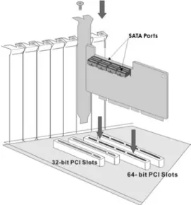
Step 3. Install the PCI RAID Cards
To install the SATA RAID adapter, remove the mounting screw and existing bracket from the rear panel behind the selected PCI slot. Align the gold-fingered edge on the card with the selected PCI ex-pansion slot . Press down gently but firmly to ensure that the card is properly seated in the slot, as shown in Figure 2-4. Then screw the bracket into the computer chassis. The card can fit in both PCI and PCI-X slots. It can get the best performance while the SATA RAID controller runs in the 64-bit/133MHz PCI-X slot.
HARDWARE INSTALLATION
Step 6 Connect the SATA cable
Model ARC-11XX and ARC-12XX have dual-layer SATA internal con-nector. If you have not already connected your SATA cables, use the cables included with your kit to connect your controller to the SATA hard drives.
The cable connectors are all identical, so it does not matter which end you connect to your controller or SATA hard drive or cage backplane SATA connector.
Figure 2-9 SATA Cable
Figure 2-8 Mount Cages & Drives
Step 5. Mount the Cages or Drives
Remove the front bezel from the computer chassis and install the Cages or SATA Drives in the computer chassis. Loading drives to the drive tray if cages are installed. Be sure that the power is con-nected to either the Cage backplane or the individual drives.
HARDWARE INSTALLATION
Step 7 Install the LED cable (optional)
SATA RAID controller provides three kinds of LED status connector. A: Global indicator connector, which lights when any drive is active. B: Individual LED indicators connector, for each channel drive. C: I2C connector, for SATA proprietary backplane enclosure. The following diagram and discription will show each type of con-nector.
Note:
A cable for the global indicator comes with your computer system. Cables for the individual drive LEDs may come with a drive cage, or you may need to purchase them.
Figure 2-10 Multi-Lance Cable
Step 6-2. Connect the Multi-lance cable
Model ARC-11XX-ML have multi-lance internal connector, each of which can support up to four SATA drives. These adapters can be installed in a server RAID enclosure with InfiniBand 4X connectors (SFF-8470) backplane.
If you have not already connected your Multi-lance cables, use the cables included with your kit to connect your controller to the Multi-lance connector backplane. The cable connectors are all identical, so it does not matter which end you connect to your controller or Multi-lance backplane connector. The following diagram shows the picture of Multi-lane cable.
Unpack and remove the PCI RAID cards. Inspect it carefully. If any-thing is missing or damaged, contact your local dealer.
HARDWARE INSTALLATION
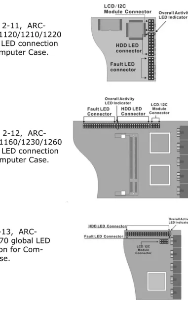
Figure 2-13, ARC-1170/1270 global LED connection for Com-puter Case.
A: Global Indicator Connector
If your system wants to show the global LED in a two-pin LED drive activity connector, use the fist two pin of the activity LED connector. The following diagram shows the connector and setting.
Figure 2-11, ARC-1110/1120/1210/1220 global LED connection for Computer Case.
Figure 2-12, ARC-1130/1160/1230/1260 global LED connection for Computer Case.
HARDWARE INSTALLATION
LED Normal Status Problem Indication Disk Activity When the activity LED is
illu-minated, there is I/O activity on that disk drive. When the LED is dark, there is no activ-ity on that disk drive.
N/A
Fault LED When the fault LED is solid illuminated, there is no disk present.
When the Red LED is slow blinking (2 times/sec), that disk drive has failed and should be hot-swaed immediately. When the Blue LED is illuminated adn Red LED is fast blinking (10 times/sec) there is rebuilding acitivity on that disk drive.
Figure 2-14, ARC-1110/1120/1210/1220 Individual LED indica-tors connector, for each channel drive.
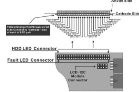
B: Individual LED indicators connector
Insert the cable from drive activity LED or fault LED connector on backplane of cage to the respective connector on the SATA RAID controller. The following table illustrate the fault/activity LED.
Figure 2-15, ARC-1130/1160/1230/1260 Individual LED indica-tors connector, for each channel drive.
HARDWARE INSTALLATION
Figure 2-17, Activity LED I2C connector connected between SATA RAID Controller & SATA HDD Cage backplane.
C: I2C Connector
You can also connect the I2C interface to the SATA proprietary backplane enclosure. This can reduce the number of activity LED or fault LED cable. The I2C interface can also cascade to another SATA backplane enclosure for the additional channel status dis-play.
Figure 2-16,
ARC-1170/1270 Individual LED indicators connector, for each channel drive.
HARDWARE INSTALLATION
Figure 2-18, Activity LED I2C connector con-nected between SATA RAID Con-troller & 2 SATA HDD Cages back-plane.
Step 8. Power up the System
Safety checks the installation, reinstall the computer cover and reconnect the power cord cables. Turn on the AC power switch at the rear of the computer then press the power button at the front of the host computer.
Step 9. Configure volume set
The adapter configures the RAID function through the McBIOS
RAID manager. Please reference the Chapter 3 McBIOS RAID
Manager for the detail configuration. The RAID configuration can also be configured by McRAID storage manager. After ArcHttp
proxy server be installed. Please refernce the Chapter 6 Web
Browser-Based Configuration.
Step 10. Install the controller driver
In a new system:
• Driver installation usually takes places as part of operating sys-tem installation. Please reference the Chapter 4 Diver Installation
HARDWARE INSTALLATION
Step 11. Install ArcHttp proxy Server
The SATA RAID controller firmware has embedded the web-browser RAID manager and SNMP agent function. ArcHttp Proxy driver will enable it. The Browser-based RAID manager provides all of the creation, management, and monitor SATA RAID controller status. Please reference the Chapter 5 for the detail ArcHtt proxy server installation. The SNM agent function please reference appendix C.
Step 12. Determining the Boot sequences
SATA RAID is a bootable controller. If your system already con-tains a bootable device with an installed operating system, you can set up your system to boot a second operating system from the new controller. To add a second bootable controller, you may need to enter Setup and change the device boot sequence so that the SATA RAID controller heads the list. If system BIOS Setup does not allow this change, your system may not be configurable to allow the SATA RAID controller to act as a second boot device.
Summary Of the installation
The flow chart below describes the installation procedures for SATA RAID controller. These procedures included hardware installa-tion, the creation and configuration of a RAID volume through the McBIOS, OS installation and installation of SATA RAID controller software.
Note:
Look for further release version driver of Linux and Free-BSD:
• See the Driver Library at http://www.areca.com.tw for the detail installation procedure.
In an existing system:
• Install the controller driver to the existing operating system. Please reference the Chapter 4 Driver Installation for the detail installation procedure.
HARDWARE INSTALLATION
Configuration Utility Operating System supported McBIOS RAID Manager OS-Independent
McRAID Storage Manager
(Via Archttp proxy server) Windows 2000/XP/2003, Linux and FreeBSD SAP Monitor
(Single Admin portal to scan for mul-tiple RAID units in the network, Via
ArcHttp Proxy Server)
Windows 2000/XP/2003 Java based for Windows.
Linux and FreeBSD (available in Q2, 2005)
SNMP Manager Console Integration
(Via ArcHttp Proxy Server) Windows 2000/XP/2003, Linux. FreeBSD (available in Q2, 2005)
The software components configure and monitor the SATA RAID controller via ArcHttp Proxy Server.
McRAID Storage Manager
Launching the Firmware-embedded web browser McRAID Storage manager, you need first to install the ArcHttp Proxy Server in your server system. If you need additional information about installation and start-up the function, see the McRAID Storage Manager section in the chapter 6.
SNMP Manager Console Integration
Launching the Firmware-embedded SNMP agent, you need first to install the ArcHttp Proxy Server in your server system. If you need additional information about installation and start-up the function, see the SNMP operation & Installation section in the Appendix-C.
HARDWARE INSTALLATION
Single Admin Portal (SAP) Monitor
Scan for multiple RAID units in the network and monitor the con-troller set status. It also includes disks stress test utility to kick out disks meeting marginal spec before the RAID unit is actually put on-line for real business.
For additional information, see the Utility manual in the package CD-ROM or download from the web site http://www.areca.com.tw.
BIOS CONFIGURATION
3. McBIOS RAID Manager
The mainboard BIOS automatically configures the SATA RAID controller parameter at power-up;
• I/O Port Address
• Interrupt channel(IRQ) • Adapter ROM Base Address
Use McBIOS to further configure the SATA RAID adapter to suit your operating system.
3.1 Starting the McBIOS RAID Manager
This section explains how to use the McBIOS Setup Utility to con-figure your RAID system. The BIOS Setup Utility is designed to be user-friendly. It is a menu-driven program, residing in the firm-ware, which allows you to scroll through its various sub-menus and select among the predetermined choices.
When starting the system with an SATA RAID controller installed, the start-up sequence displays the following message appears on your monitor:
The McBIOS configuration manager message remains on your screen for about nine seconds, giving you time to start the
config-ure menu by pressing Tab or F6. If you do not wish to enter
con-figuration menu, press <ESC> to skip configuration. When
acti-vated, the McBIOS window appears showing a selection dialog box listing the SATA RAID controller that are installed in the system. The legend at the bottom of the screen shows you what keys are enabled for the windows.
BIOS CONFIGURATION
Use Up and Down arrow keys to select the adapter you want to
configure. While a desired adapter is highlighted, press the <
En-ter> key to enter the Main Menu of the McBIOS Configuration
Util-ity.
3.2 McBIOS Configuration manager
The McBIOS configuration utility is firmware-based and uses to con-figure raid sets and volume sets. Because the utility resides in the SATA RAID controller firmware, its operation is independent of the operating systems on your computer. Use this utility to:
BIOS CONFIGURATION
3.4 Designating Drives as Hot Spares
All unused disk drive that is not part of a raid set can be created as a Hot Spare. The Quick Volume/Raid Setup configuration will automatically add the spare disk drive with the raid level for user to select. For the Raid Set Function configuration, user can use the Create Hot Spare option to define the hot spare disk drive.
A Hot Spare disk drive can be created when you choose the Cre-ate Hot Spare option in the Raid Set Function, all unused physical devices connected to the current controller appear:
Select the target disk by clicking on the appropriate check box.
Press the Enter key to select a disk drive, and press Yes in the
Create Hot Spare to designate it as a hot spare. • Define volume set,
• Add physical drive, • Modify volume set,
• Modify RAID level/stripe size, • Define pass-through disk drives, • Modify system function, and • Designate drives as hot spares.
3.3 Configuring Raid Sets and Volume Sets
You can configure raid sets and volume sets with McBIOS RAID manager using Quick Volume/Raid Setup automatically, or Raid Set/Volume Set Function manually configuration method. Each configuration method requires a different level of user input. The general flow of operations for raid set and volume set configuration is:
Step Action
1 Designate hot spares/pass-through (optional). 2 Choose a configuration method.
3 Create raid sets using the available physical drives. 4 Define volume sets using the space in the raid set.
5 Initialize the volume sets (logical drives) and use volume sets in the host OS.
BIOS CONFIGURATION
3.5 Using Quick Volume /Raid Setup
Con-figuration
In Quick Volume /Raid Setup Configuration, it collects all drives in the tray and include them in a raid set. The raid set you create is associated with exactly one volume set, and you can modify the default RAID level, stripe size, and capacity of the volume set. Des-ignating Drives as Hot Spares will also show in the raid level selec-tion opselec-tion. The volume set default settings will be:
Parameter Setting
Volume Name Volume Set # 00
SCSI Channel/SCSI ID/SCSI LUN 0/0/0
Cache Mode Write Back
Tag Queuing Yes
The default setting values can be changed after configuration is complete. Follow the steps below to create arrays using Quick Vol-ume /Raid Setup Configuration:
Step Action
1 Choose Quick Volume /Raid Setup from the main menu. The available RAID levels with hot spare for the current volume set drive are displayed. 2 Recommend use drives have same capacity in a specific array. If you use
drives with different capacities in an array, all drives in the raid set will select the lowest capacity of the drive in the raid set.
The numbers of physical drives in a specific array determine the RAID levels that can be implemented with the array.
RAID 0 requires 1 or more physical drives RAID 1 requires at least 2 physical drives RAID 1+Spare requires at least 3 physical drives RAID 3 requires at least 3 physical drives RAID 5 requires at least 3 physical drives RAID 3 +Spare requires at least 4 physical drives RAID 5 + Spare requires at least 4 physical drives RAID 6 requires at least 4 physical drives
RAID 6 + Spare requires at least 5 physical drives
Highlight RAID level for the volume set and press Enter key to confirm. 3 Set the capacity size for the current volume set. After Highlight RAID
level and press Enter key.
The selected capacity for the current volume set is displayed. Using the
UP and DOWN arrow key to create the current volume set capacity size and press Enter key to confirm. The available stripe sizes for the current volume set are displayed.
BIOS CONFIGURATION
3.6 Using Raid Set/Volume Set Function
Method
In Raid Set Function, you can use the Create Raid Set function to generate the new raid set. In Volume Set Function, you can use the Create Volume Set function to generate its associated volume set and parameters.
If the current controller has unused physical devices connected, you can choose the Create Hot Spare option in the Raid Set Func-tion to define a global hot spare. Select this method to configure new raid sets and volume sets. The Raid Set/Volume Set Function configuration option allows you to associate volume set with partial and full raid set.
4 Using UP and DOWN arrow key to select the current volume set stripe size and press Enter key to confirm it. This parameter specifies the size of the stripes written to each disk in a RAID 0, 1, 5 or 6 Volume Set. You can set the stripe size to 4 KB, 8 KB, 16 KB, 32 KB, 64 KB, or 128 KB. A larger stripe size provides better-read performance, especially if your computer does mostly sequential reads. However, if you are sure that your computer does random read requests more often, choose a small stripe size.
5 When you are finished defining the volume set, press Enter key to con-firm the Quick Volume And Raid Set Setup function.
6 Foreground (Fast Completion) Press Enter key to define fast initialization or Selected the Background (Instant Available). In the background Ini-tialization, the initialization proceeds as a background task, the volume set is fully accessible for system reads and writes. The operating system can instantly access to the newly created arrays without requiring a reboot and waiting the initialization complete. In Fast Initialization, the initialization proceeds must be completed before the volume set ready for system accesses.
7 Initialize the volume set you have just configured
8 If you need to add additional volume set, using main menu Create Vol-ume Set function
BIOS CONFIGURATION
Step Action
1 To setup the Hot Spare (option), choose Raid Set Function from the main menu. Select the Create Hot Spare and press Enter key to set the Hot Spare.
2 Choose Raid Set Function from the main menu. Select the Create Raid Set and press Enter key.
3 Select a Drive For Raid Set window is displayed showing the IDE drive connected to the current controller.
4 Press UP and DOWN arrow keys to select specific physical drives. Press the Enter key to associate the selected physical drive with the current raid set.
Recommend use drives has same capacity in a specific raid set. If you use drives with different capacities in an array, all drives in the raid set will select the lowest capacity of the drive in the raid set.
The numbers of physical drives in a specific raid set determine the RAID levels that can be implemented with the raid set.
RAID 0 requires 1 or more physical drives per raid set. RAID 1 requires at least 2 physical drives per raid set. RAID 3 requires at least 3 physical drives per raid set. RAID 5 requires at least 3 physical drives per raid set. RAID 6 requires at least 4 physical drives per raid set.
5 After adding physical drives to the current raid set as desired, press Yes to confirm the Create Raid Set function.
6 An Edit The Raid Set Name dialog box appears. Enter 1 to 15 alphanu-meric characters to define a unique identifier for a raid set. The default raid set name will always appear as Raid Set. #. Press Enter to finish the name editing.
7 Press Enter key when you are finished creating the current raid set. To continue defining another raid set, repeat step 3. To begin volume set configuration, go to step 8.
8 Choose Volume Set Function from the Main menu. Select the Create Volume Set and press Enter key.
9 Choose one raid set from the Create Volume From Raid Set window. Press Enter key to confirm it.
10 Foreground (Fast Completion) Press Enter key to define fast initialization or Selected the Background (Instant Available). In the background Ini-tialization, the initialization proceeds as a background task, the volume set is fully accessible for system reads and writes. The operating system can instantly access to the newly created arrays without requiring a reboot and waiting the initialization complete. In Fast Initialization, the initialization proceeds must be completed before the volume set ready for system accesses.
11 If space remains in the raid set, the next volume set can be configured. Repeat steps 8 to 10 to configure another volume set.
BIOS CONFIGURATION
3.7 Main Menu
The main menu shows all function that enables the customer to execute actions by clicking on the appropriate link.
Note:
User can use this method to examine the existing con-figuration. Modify volume set configuration method provides the same functions as create volume set con-figuration method. In volume set function, you can use the modify volume set function to modify the volume set parameters except the capacity size:
Note:
The manufacture de-fault password is set
at 0000, this
pass-word can be mod-ify by selected the
Change Password
in the section of Raid
System Function.
Option Description
Quick Volume/Raid Setup Create a default configuration which based on num-bers of physical disk installed
Raid Set Function Create a customized raid set Volume Set Function Create a customized volume set Physical Drives View individual disk information Raid System Function Setting the raid system configuration
Ethernet Configuration Ethernet LAN setting (ARC-1x30/1x60/1x70 only) View System Events Record all system events in the buffer
Clear Event Buffer Clear all event buffer information Hardware Monitor Show all system environment status System Information View the controller information
BIOS CONFIGURATION
This password option allows user to set or clear the raid controller’s password protection feature. Once the password has been set, the user can only monitor and configure the raid controller by providing the correct password. The password is used to protect the internal RAID controller from unauthorized entry. The controller will check the password only when entering the Main menu from the initial screen. The RAID controller will automatically go back to the initial screen when it does not receive any command in twenty seconds.
3.7.1 Quick Volume/RAID Setup
Quick Volume/RAID Setup is the fastest way to prepare a raid set and volume set. It only needs a few keystrokes to complete it. Although disk drives of different capacity may be used in the raid set, it will use the smallest capacity of disk drive as the capacity of all disk drives in the raid set. The Quick Volume/RAID Setup option creates a raid set with the following properties:
1. All of the physical drives are contained in a raid set.
2. The raid levels associated with hot spare, capacity, and stripe size are selected during the configuration process.
3. A single volume set is created and consumed all or a portion of the disk capacity available in this raid set.
4. If you need to add additional volume set, using main menu Create Volume set function.
The total physical drives in a specific raid set determine the RAID
levels that can be implemented with the raid set. Press the Quick
Volume/RAID Setup from the main menu; all possible RAID levels screen will be displayed.
BIOS CONFIGURATION
A single volume set is created and consumed all or a portion of the disk capacity available in this raid set. Define the capacity of volume set in the Available Capacity popup. The default value for the volume set is displayed in the selected capacity. To enter a value less than the available capacity, type the value and press the Enter key to accept this value. If it only use part of the raid
set capacity, you can use the Create Volume Set option to
de-fine another volume sets
Stripe size This parameter sets the size of the stripe written to each disk in a RAID 0, 1, 3, or 5 logical drive. You can set the stripe size to 4 KB, 8 KB, 16 KB, 32 KB, 64 KB, or 128 KB.
A larger stripe size produces better-read performance, especially if your computer does mostly sequential reads. However, if you are sure that your computer does random reads more often, se-lect a small stripe size.