International Journal of Research in Engineering & Applied Sciences
Email:- [email protected], http://www.euroasiapub.org
33
Evaluation of Principal strain and its direction due to three dimensional finite
element stresses during Impact of structural dynamic load
Dr Sanjay Gupta
Associate Professor, Department of civil engineering, Faculty of Engineering and Technology, Manav Rachana International University, Faridabad
Abstract:
The significance of the principal strain, principal stress and their direction were estimated while designing the structural dynamics structure. The prediction of the wall could be assessed in advance with the help of the aforesaid case studies. The analysis were made for the three dimensional finite element method and based on the above case studies the finite element strain , stress and direction were estimated were listed in the result and discussion. The Critical strains were estimated of the aforesaid structural dynamic load over the base of the footing. It was observed that the higher depth the clear indication of flatter direction and steeper direction strain were assessed in the case studies just below the excavated boundary, it gave the advance awareness of the stability of the vertical wall of excavated boundary. Hence the foundation structure before that the stabilization of the vertical cut at below the 12 m or so were exactly assessed , however the discretization the continuum or physical bodies in the three dimensional finite element analysis for strain , stress , and direction were became the realistic approaches. Key word: Principal strain, principal strain direction, continuum vibration engineering, vertical motion, mathematical modeling, bearing pressure, three dimensional stresses1.
Introduction of Problem
: An extension of the author international published paper of the structural dynamics problem to the hydro power engineering with two dimensional
stresses analysis . The Turbo generator had been analyzed for the a depth of 12.0 m from
International Journal of Research in Engineering & Applied Sciences
Email:- [email protected], http://www.euroasiapub.org
34
Analytical analysis for the worst possible combination of moment based on vibration , vertical dynamic amplitude ,static and dynamic load condition as under :X
60KN 40KN B3
B1 700KN/35KN
B2 700KN/35KN
60KN 40KN
Y
X-Y Axes 4.4mX7.0m
Z B4
C2
C1 Plate soil Z=6.5mx7.0m Y C3
C1 B C2 C3
International Journal of Research in Engineering & Applied Sciences
Email:- [email protected], http://www.euroasiapub.org
35
2.Methodology of Analysis :2.1 The solution of the above problem gave Bending Moment chart and worst possible combination of moment :2.2 The variation of Sagging Moment for vertical load, UDL,Vertical and Horizontal Dynamic Load ,earth quake ,differential temperature etc
The variation of Hogging Moment for vertical load, UDL,Vertical and Horizontal Dynamic Load ,earth quake ,differential temperature etc
The graphical representation in plate number 01 showed the higher moment in the Mp in KN m were sagging in nature , however at the MB the moment were shown hogging in nature and at MA , the nature of the moment were observed as sagging .These three moment were estimated only for the vertical load . The similar type of the moment were estimated in case of the application of uniformly distributed load .The percentage of variation of 16% of Mp and 20 % of Mp for Moment MA in case of Vertical load and uniformly distributed. The moment due to vertical and horizontal dynamic load over the structure were estimated for all these location such as MA , MB and Mp . The vertical Dynamic load over the above location developed the Hogging as well as sagging moment , the maximum moment due to the above condition were estimated and were shown in the graph for Mp location only . However the moment for the MA and MB were estimated and shown in graph . The nature of the moment were seen as sagging and hogging in nature . The earth quake moment were also estimated. The highest value were estimated and shown in the graph for
0 50 100 150 200 250 300 350 400 450 500 P( Vertical load ) Q,UDL V(Vertical Dynamic load) H(Horizontal Dynamic load)
Earth quake Differential temperature
Shrinkage
MA KN-m
MB KN-m
Mp KN-m
-300 -250 -200 -150 -100 -50 0 P( Vertical load ) Q,UDL V(Vertical Dynamic load) H(Horizontal Dynamic load)
Earth quake Differential temperature
Shrinkage
MA KN-m
MB KN-m
International Journal of Research in Engineering & Applied Sciences
Email:- [email protected], http://www.euroasiapub.org
36
MA . The highest sagging moment were estimated for the MA location due to differential temperature compared to MB . The nature of the moment is sagging in nature . However the nature of the moment other than MA were estimated as Hogging in nature .The Highest Hogging moment were estimated in MA compared to MB and Mp where the moment were estimated as Positive . The combination of all Moment gave an estimation to analyze the most worst and critical condition of moment. The variation of the moment in all three case were estimated and shown in the graph . The highest sagging moment for the case MA were seen in the graph sheet . The MB showed the hogging moment in the graph .2.3 Result of Amplitude and Frequencies
The vertical amplitude were estimated
Variation of the amplitude along the vertical plane shown at the different location of the structure; The highest amplitude at the location B were estimated and showed in the above bar chart . But the amplitude at the location A and P were estimated lower than the location B .
2.4 Variation of the frequency along the plane shown at the different location of the Structure: The highest frequency was observed on the location P , However the lowest Frequency was seen on the location B as shown in the Bar chart. The variation of the frequency on the location B was estimated as 7% less compared to the location P .
0 0.002 0.004 0.006 0.008 0.01 0.012 0.014
Amplitude in mm
AT A
AT B
AT P
2150 2200 2250 2300 2350 2400 2450 2500 2550 2600 2650
Frequencies in rpm
at A
at B
International Journal of Research in Engineering & Applied Sciences
Email:- [email protected], http://www.euroasiapub.org
37
2.5 Worst Possible combination of Bending Moment: Worst possible combinations of the moment along the location P were visualized highest in respect of the maximum value of the moment. However the nature of the moment were estimated as Sagging in nature as shown in the bar chart. The maximum hogging moment were estimated along the location B . However hogging moment were created minimum at the location A as represented in the Bar Chart .The variation of moment maximum and minimum represented in Bar chart.2.6 Varition of minimum Hogging moment at the different locaton A,D AND AT 2 -140
-120 -100 -80 -60 -40 -20 0
Minimum Bending Moment
Bending Moment at A and D
Bending Moment
Bending Moment2
-600 -400 -200 0
Maximum Bending Moment
Bending Moment at A and D
Bending Moment
Bending Moment2 0
100 200 300 400 500 600 700 800
Maximum Bending Moment
Minimum Bending Moment
Bending Moment at A and D
Bending Moment
International Journal of Research in Engineering & Applied Sciences
Email:- [email protected], http://www.euroasiapub.org
38
2.7 Variation of Hogging moment2.8 Service Moment and Shear Forces
Moment MA= +475.129 KN-m,Moment MB = - 492.256 KN-m, Maximum Possible Moment at center of span BC =692.162- 492.256 =199.906 KN-m
Factored Moment were computed as under MUA =1.5 * 475.129 = 712.6935 KN-M MUB=1.5*492.256 = 738.384 KN-m,
Positive B.M. at the center of BC = 1.5* 199.960 = 299.859 KN-m, Factored shear forces at B=1.5 * 907.62 = 1361.43 KN,Working Shear forces at A =(MA + MB)/4 = 241.84625 KN
Factored shear Forces at A =1.58 *241.84 = 362.769 KN
Design of Beam Section
IS: 456-2000 , clause 38.1, The ultimate Moment= 299.859 KN-m The moment of resistance of the T-section assuming the normal axes
MUR = 0.36 fck bf Df *( d-0.42 Df) = 3.581000/6 + 1.2*1000 + 6*120 = 2503 mm
Design of foundation structure using modern techniques based on the result of three dimensional excavation using finite element method : Axial load on column = 1361.43 KN,self wt of column = 1.0*1.0*12*24 = 288 KN, self wt of foundation at 10 % = 164.93 KN,Total load W = 1814.36 KN,Moment at the base =475.129 KN-m, Eccentricity e = M/P,=475.129/1814.36 = 0.26187 m ==261.87 mm.
The worst Possible combination of load at the bottom of the foundation structure
The applications of load over the area were considered as 4000 KN/m2.
3.0 Result and Discussion: The principal strain and direction of principal strain for three dimensional excavation using finite element method:
The graph of the principal strain and direction of principal strain were presented in graph 01 to 05 under the sub head principal strain and direction of strain for three dimensional excavation using finite element method .
0 1000 2000 3000 4000 5000
load KN
Load (Working Load)
Load 2(FS=1.5)
International Journal of Research in Engineering & Applied Sciences
Email:- [email protected], http://www.euroasiapub.org
39
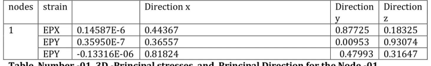
3.1 Three Dimensional -Principal stresses and Principal Direction for the Node -01nodes strain Direction x Direction y
Direction z
1 EPX 0.14587E-6 0.44367 0.87725 0.18325 EPY 0.35950E-7 0.36557 0.00953 0.93074 EPY -0.13316E-06 0.81824 0.47993 0.31647
Table Number -01, 3D -Principal stresses and Principal Direction for the Node -01
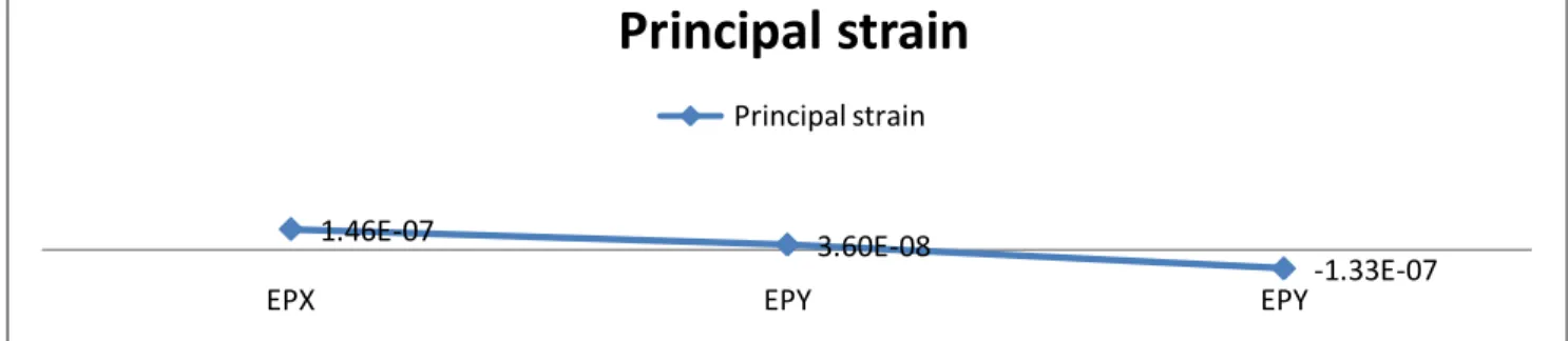
Graphical presentation Plate Number -01, 3D -Principal strain and Principal Direction for the Node -01
The strain EPX of node 01 had magnitude of 0.14587 E-01 .The direction of strain EPX was 0 26’ 28.4’’ along the x-axis . The direction of strain EPX was 0 52’ 38.1’’ along y-axis. The direction of strain EPX was 0 10’ 59.7’’ along z-axis . The strain EPY of node 01 had magnitude of 0.35950e-07 .The direction of strain EPY was 0 26’ 28.4’’ along the major axes . The direction of strain EPY was 0 21’55.8’’ along minor axes. The direction of strain EPY was 0 55’ 48’’ along z-axis. The strain EPZ of node 01 had magnitude of -0.1331e-06 .The direction of strain EPZ was 0 49’ 5.66’’ along the major axes . The direction of strain EPZ was 0 28’ 47.75’’ along minor axes The direction of strain EPX was 0 18’ 59.7’’ along intermediate axes .These values were presented in the table and graph -01 .The principal strain observed for the intermediate axes were negative in nature . The strain direction was estimated as steeper along the major axes than the minor and intermediate axes direction. These values were assessed for the strain along intermediate axes .The higher value of principal strain were estimated along the major axes compared to the intermediate and minor principal axes . Hence during the excavation the extreme care should ve taken for the intermediate strain as the value was estimated as negative .These values were shown in the graph number-01 and table number -01 for the principal strain and direction of principal strain.
1.46E-07 3.60E-08 -1.33E-07
2.8
0.44367 0.36557 0.81824
5
0.87725 0.00953 0.47993
0
0.18325 0.93074 0.31647
0
EPX EPY EPY 4.5
principal strain and Direction of principal strain
International Journal of Research in Engineering & Applied Sciences
Email:- [email protected], http://www.euroasiapub.org
40
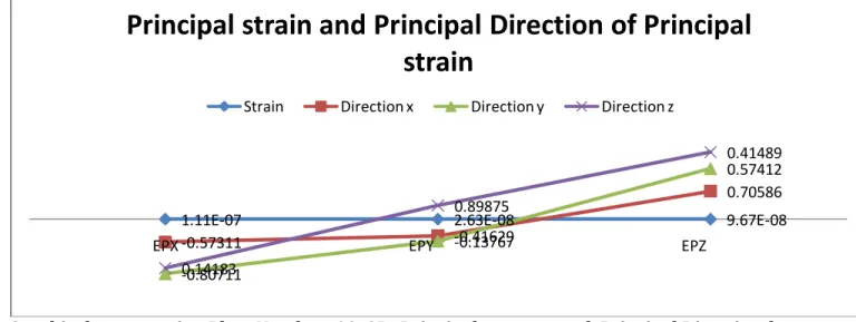
3.2 Graphical presentation Plate Number -02, 3D -Principal strain and Principal Direction for the Node -01 :Graphical presentation Plate Number -02, 3D -Principal strain and Principal Direction for the Node -02
Table Number -02, 3D -Principal stresses and Principal Direction for the Node -02
The strain EPX of node 02 had magnitude of .11056e-06 .The direction of strain EPX was 0 34’ 32.2’’ along the major axes . The direction of strain EPX was 0 48’ 25.6’’ along minor axes. The direction of strain EPX was 0 8’ 30.59’’ along intermediate axes . The strain EPY of node 02 had magnitude of 0.26258E-07 .The direction of strain EPY was 0 24’ 58.64’’ along the major principal axes . The direction of strain EPY was -0 8’ 15.61’’ along minor principal axes. The direction of strain EPY was 0 13’55.5’’along intermediate axes. The strain EPZ of node 02 had magnitude of 0.9671e-07.The direction of strain EPZ was 0 42’21.1’’ along the major principal axes . The direction of strain EPZ was 0 24’ 53.6’’ along minor axes. The direction of strain EPZ was 0 24’ 53.6’’ along intermediate axes. These values were presented in the table and graph -02 .The value of principal strain were estimated as such higher than the value of the strain along the minor principal axes and intermediate axes. The direction of the principal strain was steeper than the strain along the major and intermediate axes for the strain along the principal strain axes. The strain direction was estimated along the minor axes for minor principal axes. Thus the reverse direction was estimated in the case of strain along the minor axes ,but the direction of the strain along the intermediate principal axes was estimated steeper along the major principal strain. Extreme care should be taken during excavation of three dimensional excavation using finite element method along the major principal axes for element number -02 .The values were presented in the graph number -02 for the principal strain and direction of principal strain .
1.46E-07 3.60E-08
-1.33E-07
EPX EPY EPY
Principal strain
Principal strain
Nodes Strain Code
Strain Direction x Direction y Direction z
2 EPX .11056E-06
-0.57311 -0.80711 0.14183
EPY 0.26258E-07
-0.41629 -0.13767 0.89875
EPZ 0.96713E-7
International Journal of Research in Engineering & Applied Sciences
Email:- [email protected], http://www.euroasiapub.org
41
3.3. Graphical presentation Plate Number -03, 3D -Principal stresses and PrincipalDirection for the Node -02:
Graphical presentation Plate Number -03, 3D -Principal stresses and Principal Direction for the Node -03
Nodes Strain Code
Strain Direction x Direction
y
Direction z
3 EPX 0.87914E-7
-0.54452 0.83870 -0.00925
EPY 0.39570E-7
0.23926 0.16589 0.95668
EPZ - 0.13679E-06
0.80390
0.51872
-0.29100
Table Number -03 , 3D -Principal stresses and Principal Direction for the Node -03
The strain EPX of node 03 had magnitude of 0.8791e-07.The direction of strain EPX was 0 32’40.27’’ along the x-axis. The direction of strain EPX was 0 50’ 19.32’’ along y-axis .The direction of strain EPX was 0 0’33.3’’ along intermediate axes .The strain EPY of node 03 had magnitude of 0.39570E-07 .The direction of strain EPY was 0 14’21.34’’ along major axes. The direction of strain EPY was 9’57.2’’ along minor axes. The direction of strin EPY was 0 57’ 24.05’’ along intermediate axes. The strain EPZ of node 03 had a magnitude of -.13679e-06.The direction of strain EPZ was 0 48’14.04’’ along axes. The direction of strain EPZ was 0 31’ 7.39’’ along minor axes .The direction os strain EPX was -0 17’27.6’’ along intermediate axes. It was observed during the vertical excavation the strain along the intermediate axes estimated higher than the strain rate along principal strain and minor principal strain .The steeper gradient were estimate for the minor axes while excavation being carried out along the principal axes. However the directions along the intermediate axes were estimated as flattened compared to the minor axes and major principal axes. The care should be required while excavation along the intermediate axes . These values were presented in the table and graph -03 .
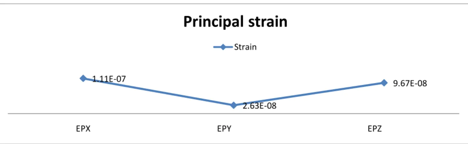
1.11E-07 2.63E-08 9.67E-08
-0.57311 -0.41629
0.70586
-0.80711
-0.13767
0.57412
0.14183
0.89875
0.41489
EPX EPY EPZ
Principal strain and Principal Direction of Principal
strain
International Journal of Research in Engineering & Applied Sciences
Email:- [email protected], http://www.euroasiapub.org
42
3.4 Graphical presentation Plate Number -04, 3D -Principal stresses and Principal Direction for the Node -04;Graphical presentation Plate Number -04, 3D -Principal stresses and Principal Direction for the Node -04
The strain EPX,EPY ,EPZ of number - 04 had a magnitude of 0.131E-06 ,-41519E-07,-01373E-06 respectively. The principal strain for the minor and intermediate axes were estimated as negative .Hence the value of the Intermediate principal strain gave quite higher negative value compared to negative value of the minor principal strain . The principal strain for the major axes was estimated positive for the element number -04 . The direction of strain EPX was 0 37’30.86’’,046’15.49’’,0 7’16.03’’ respectively along principal axes ,minor principal axes and intermediate axes .The direction of principal strain was estimated flatter along the minor axes compared to major and intermediate axes .However the steeper gradient was estimated along the intermediate axes .The direction of strain EPY was 0 5’ 46.5’’,0 13’ 48.65’’ and 0 46’28.09’’ along the principal major axes, minor principal axes and intermediate principal axes .The direction of principal strain for the principal major axes were estimated as steeper compared to the intermediate and minor axes. The direction of strain EPZ was 0 46’28.09’’,035’37.72’’ and -0 13’5.23’’ along x-axes,yaxes,z-axes. The negative direction of intermediate principal axes was estimated and was flatter than the intermediate principal axes .These values were presented in the table and graph -04 .
Nodes Strain Code
Strain Direction x Direction
y
Direction z
4 EPX 0.13135E-6
-0.62524 0.77097 -0.12112
EPY -0.41519E-7
0.09625
0.23018
0.96838
EPZ - 0.10373E-06
0.77447 0.59381 -.21812
Table Number -04, 3D -Principal stresses and Principal Direction for the Node -04 1.11E-07
2.63E-08
9.67E-08
EPX EPY EPZ
Principal strain
International Journal of Research in Engineering & Applied Sciences
Email:- [email protected], http://www.euroasiapub.org
43
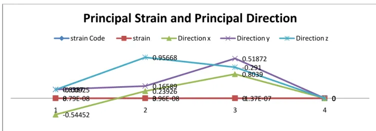
3.5 Graphical presentation Plate Number -05, 3D -Principal stresses and Principal Direction for the Node -05Graphical presentation Plate Number -05, 3D -Principal stresses and Principal Direction for the Node -05
Table Number -05 , 3D -Principal stresses and Principal Direction for the Node -05
The strain EPX,EPY,EPZ of node 04 had magnitude of 0.12040e-06,-.2458e-07,-.10957e-06.The negative value for the intermediate and minor strain were estimated. The vertical excavation at these location were very critical and extreme care should be taken during element number -04 .The direction of strain EPX was 0 43’53.5’’,-0 40’13.82’’,05’44.34’’ respectively along the major principal axes ,minor principal axes, intermediate axes . The steeper gradient was estimated along the intermediate axes .These flatter gradient were estimated for the major and minor principal strain .Hence extreme care should be required in the case of minor principal strain direction as the value of the direction became negative .The direction of strain EPY was 0 7’ 3.14’’,0 15’47.02’’,0 57’27.32’’ along the major principal axes ,minor principal axes, intermediate axes. The direction of strain EPZ was 0 40’17.76’’,0 41’21.37’’.0 16’ 18.41’’ along the major principal axes ,minor principal axes, intermediate axes. These values were presented in the table and graph -05.
0 0 0 0
8.79E-08 3.96E-08 -1.37E-07 0
-0.54452
0.23926
0.8039
0
0.8387 0.16589
0.51872
0 -0.00925
0.95668
-0.291
0
1 2 3 4
Principal Strain and Principal Direction
strain Code strain Direction x Direction y Direction z
Nodes Strain Code
Strain Direction x Direction y Direction z
5 EPX 0.12040E-06
0.73153 -0.67506 0.09565
EPY - 0.24581E-07
0.11754 0.26306 0.95759
EPZ -0.10957E-06
International Journal of Research in Engineering & Applied Sciences
Email:- [email protected], http://www.euroasiapub.org
44
3.6 Graphical presentation Plate Number -06, 3D -Principal stresses and Principal Direction for the Node -06 ;Graphical presentation Plate Number -06, 3D -Principal stresses and Principal Direction for the Node -06
The strain EPX,EPY,EPZ of node 06 had magnitude of 8.7980e-063.968e-08,-1.376e-07.The negative value for the minor principal estimated. The vertical excavation at these location were very critical and extreme care should be taken during element number -06 for minor principal strain .
3.7Graphical presentation Plate Number -07, 3D -Principal stresses and Principal Direction for the Node -04 ;
Graphical presentation Plate Number -07, 3D -Principal stresses and Principal Direction for the Node -07
The strain EPX,EPY,EPZ of node 07 had magnitude of 2.926e-07 ,-0.198e-08, -1.048e-07 .The negative value for the intermediate and minor strain were estimated. The vertical excavation at these location were very critical and extreme care should be taken during element number -07.
8.79E-08
3.96E-08
-1.37E-07
EPX EPY EPZ
Principal Strain
Strain
1.31E-07 -4.15E-08 -1.04E-07
-0.62524
0.09625
0.77447
0.77097 0.23018
0.59381
-0.12112
0.96838 -0.21812
EPX EPY EPZ
Principal strain and Principal Direction
International Journal of Research in Engineering & Applied Sciences
Email:- [email protected], http://www.euroasiapub.org
45
3.8 Graphical presentation Plate Number -08, 3D -Principal stresses and Principal Direction for the Node -05Graphical presentation Plate Number -08, 3D -Principal stresses and Principal Direction for the Node -08
The strain EPX,EPY,EPZ of node 04 had magnitude of 2.207e-07, 2.461e-08, -1.105e-07.The negative value for the intermediate and minor strain were estimated. The vertical excavation at these location were very critical and extreme care should be taken during element number -08. 5.0 Conclusion :
i.. The nature of principal strain were estimated tensile along the minor axes. The directions of the major principal strain obtained based on the finite element were quite higher than intermediate and minor axes.
ii.The negative stresses were developed during the excavation at the higher depth of excavation. The vertical excavation became critical. Hence extreme cares were required. The cohesive strength obtained as such for element showed that the material would have the lower cohesive strength corresponding to higher element layer.
Iii .The major principal strain at the higher depth of excavation had quite higher value and had significant effect over the excavated boundary at the corners and vertical cut compared to minor and intermediate strain. Henceforth extreme cares were needed for vertical excavation.
Iv .The principal strain observed for the intermediate axes were negative in nature. The strain direction was estimated as steeper along the major axes than the minor and intermediate axes direction. These values were assessed for the strain along intermediate axes .The higher value of principal strain were estimated along the major axes compared to the intermediate and minor principal axes. Hence during the excavation the extreme care should ve taken for the intermediate strain as the value was estimated as negative.
v.The values of principal strain were estimated as such higher than the value of the strain along the minor principal axes and intermediate axes. The direction of the principal strain was steeper than the strain along the major and intermediate axes for the strain along the principal strain axes. The strain direction was estimated along the minor axes for minor principal axes. Thus the reverse direction was estimated in the case of strain along the minor axes, but the direction of the strain
1.20E-07 -2.46E-08 0 -1.10E-07
0.73153
0.11754 0
0.6716
-0.67506
0.26306
0
0.68927
0.09565
0.95759
0
0.27178
EPX EPY EPZ
Principal strain and Principal Direction
International Journal of Research in Engineering & Applied Sciences
Email:- [email protected], http://www.euroasiapub.org
46
along the intermediate principal axes was estimated steeper along the major principal strain. Extreme care should be taken during excavation of three dimensional excavation using finite element method along the major principal axes for element number -02 vi It was observed during the vertical excavation the strain along the intermediate axes estimated higher than the strain rate along principal strain and minor principal strain .The steeper gradient were estimate for the minor axes while excavation was being carried out along the principal axes. However the directions along the intermediate axes were estimated as flattened compared to the minor axes and major principal axes. The care should be required while excavation along the intermediate axes
vii. The principal strain for the minor and intermediate axes were estimated as negative .Hence the value of the Intermediate principal strain gave quite higher negative value compared to negative value of the minor principal strain .The direction of principal strain was estimated flatter along the minor axes compared to major and intermediate axes .However the steeper gradient was estimated along the intermediate axes . The direction of principal strain for the principal major axes were estimated as steeper compared to the intermediate and minor axes. . The negative direction of intermediate principal axes was estimated and was flatter than the intermediate principal axes.
viii. The direction of strain EPX was 0 43’53.5’’,-0 40’13.82’’,05’44.34’’ respectively along the major principal axes ,minor principal axes, intermediate axes . The steeper gradient was estimated along the intermediate axes .These flatter gradient were estimated for the major and minor principal strain .Hence extreme care should be required in the case of minor principal strain direction as the value of the direction became negative.
6.0 Reference
1.Kim, S.J. and Elnashai, A.S., (2008). “Seismic assessment of RC structure considering Vertical Ground Motion”, MAE centre report no 08-03, Mid American earthquake center Papazoglou,
2.A.J. and Elnashai, A.S., (1996). “Analytical and Field Evidence of the Damaging Effect of Vertical earthquake Ground Motion”, Earthquake Engineering and Structural Dynamics, Vol. 25, 1109-1137. 3.Kunnath, S.K., Abrahamson, N., Chai, Y.H., Erduran, E., and Yilmaz, Z., (2008).“Development of Guidelines for Incorporation of Vertical Ground Motion Effects inSeismic Design of Highway Bridges”, Technical report CA/UCD-SESM-08-01,University of California at Davis.
4.O. Papadopoulou,(1996) “The effect of vertical excitation on reinforced concrete multi-storey structures”, M.Sc. Dissertation, Imperial College, August 1989 from “Analytical and Field Evidence of the Damaging Effect of Vertical earthquake Ground Motion”,Earthquake Engineering and Structural Dynamics, Vol. 25, 1109-1137
3. M. Georgantzis, (1996) “Effect of vertical motion on behavior factors”, M.ScDissertation,Imperial College, August 1995. from “Analytical and Field Evidence of the Damaging Effect of Vertical earthquake Ground Motion”, Earthquake Engineering and Structural Dynamics, Vol. 25, 1109-1137.
4. S. N. Koukleri,(1996)“The effect of vertical ground excitation on the response of RCstructures”, M.Sc. Dissertation, Imperial College, August 1992. from “Analytical and Field Evidence of the Damaging Effect of Vertical earthquake Ground Motion”,Earthquake Engineering and Structural Dynamics, Vol. 25,-1137.
International Journal of Research in Engineering & Applied Sciences
Email:- [email protected], http://www.euroasiapub.org
47
“Design Provisions for Earthquake Resistance of Structures - Part 5:Foundations, Retaining Structures and Geotechnical Aspects”, ENV 1998-5, CENEuropean Committee for Standardisation,
6. BrusselsElnashai, A.S. and Papazoglou, A.J., (1997).“Procedure and Spectra for Analysis of RCStructures Subjected to Strong Vertical Earthquake Loads”, Journal of Earthquake Engineering, Vol. 1 (1), 121-156.B. Sheathe, (2009)”Effects of near field vertical acceleration on seismic response of the long span cable stayed bridge”, Msc, Dissertation, Pulchok campus IOE,
7.Tribhuwanuniversity.Saadeghvaziri, M A; Foutch, D A (1991); “Dynamic behavior of R/C highway bridgesunder the combined effect of vertical and horizontal earthquake motions”, Earthquakeengrg. and strut, dyn. Vol20,535-549,1991
8. Raheem, S A; Hayashikawa, T; Aly, G A (2001); “Effect of vertical ground motion onseismic response of steel tower of cable-stayed bridge”, proceedings of Hokkaido chapter of Japan society of civil engineers, JSCE, No 58(A), pp.112-115
9.Kalkan ,E; Graizer,V (2007). “Multi component ground motion response spectra for coupled horizontal, vertical, angular acceleration and tilt”, ISET Journal of Earthquake Technology, Paper No. 485, Vol. 44, No. 1, March 2007, pp. 259–284
10. Pamuk, A., Kalkan, E. and Ling, H.I. (2005). “Structural and Geotechnical Impacts of Surface Rupture on Highway Structures during Recent Earthquakes in Turkey”, Soil Dynamics and Earthquake Engineering, Vol. 25, No. 7-10, pp. 581–589.
11. Kalkan, E. and Gülkan, P. (2004b). “Empirical attenuation Equations for Vertical GroundMotion in Turkey”, Earthquake Spectra, Vol. 20, No. 3, pp. 853–882. Newmark, N.M., Blume, J.A. and Kapur, K.K. (1973). “Seismic Design Spectra for Nuclear Power Plants”, Journal of the Power Division,