The Study of the Tensile Strength of AlSi21CuNiMg Silumin
in the Final Stage of Solidification and the Initial Stage of Cooling
Remigiusz Romankiewicz*
University of Zielona Góra, Faculty of Mechanical Engineering, Licealna St. 9, 65-417, Zielona Góra *e-mail: [email protected]
Received: 7 July 2019/Accepted: 17 September 2019/Published online: 30 September 2019 This article is published with open access by AGH University of Science and Technology Press
Abstract
The paper presents the results of tensile strength tests of AlSi21CuNiMg silumin made on a test stand. Silumin was under examination in an unmodified state and after modification with AlCu19P1.4 master alloy in quantity of 0.2% in relation to the mass of the alloy. Using a scanning microscope, the surface fractures obtained from tensile tests were tested. The structure and profiles of fractures were examined using an optical microscope. Modification of the tested silumin resulted in a favorable fragmentation and regular distribution of the crystals of the primary silicon in the alloy structure, which led to an almost twofold increase in the strength of the silumin samples at the final solidification stage from 3.5 to 6.6 MPa. As a result of these changes, the resistance of silumin to hot cracks should increase, which is of great importance when casting hypereutectic silumin in a metal mould that strongly inhibits the shrinkage of the castings.
Keywords:
silumin, solidification, modification, tensile strength
1. INTRODUCTION
The structure of silumin has a significant effect on its me-chanical properties, mainly being formed in both a crystal-lization process [1–4] and a possible heat treatment. This effect is also highly determined by the process of primary crystallization and the morphology of the structure being formed [5]. The state of the casting structure also deter-mines its mechanical properties, especially in the final stage of solidification and the initial stage of self-cooling. Then, the unwanted morphology of the leading phase and the uneven distribution of the remaining structural phase components can significantly reduce the ductility and tensile strength of an alloy, causing the tendency for hot cracking to occur. This is particularly important when casting silumin into metal moulds, in which there is a strong inhibition of the shrinkage of castings, which often causes the formation of hot cracks.
This is the reason why it is desirable to test silumin strength during the transition from a liquid to a solid state.
2. DESCRIPTION OF THE EXPERIMENTS
Tests of tensile strength in the final stage of solidifica-tion and the initial stage of cooling were carried out for AlSi21CuNiMg silumin with the chemical composition given in Table 1.
Melting and modification of the tested alloy was carried out in a chamotte-graphite crucible in a resistance furnace with a vertical heating chamber. The modification was carried out after the metal bath was overheated to a tem-perature of 1003K (730°C). The modifying additive was AlCu19P1.4 master alloy in quantity of 0.2% in relation to the mass of the alloy. The tests were carried out 10 min after adding the modifying master alloy to the liquid alloy.
Table 1
Chemical composition of silumin AlSi21CuNiMg
Element Si Cu Ni Mg Mn Fe Al
The tensile strength tests of solidifying and cooling silumin were carried out at the test stand shown in Figure 1 [6, 7].
In the metal mould, a cylindrical cast with a diameter of
f40 and a height of 70 mm was stretching. The test metal was poured from the top into a two-part mould, which divid-ed half 5 was fixdivid-ed in the base 2. The dividdivid-ed moving upper half 6 was set in motion by the piston rod 14 of the hydraulic cylinder 13. The pump used in the device allowed pressure up to 160 bar to be obtained, and the choice of working pres-sure was carried out with the help of an adjustable prespres-sure valve. The selection of the speed of movement of the hydrau-lic cylinder rod was carried out with the help of an adjust-able valve placed in the control panel 15. The force with
which the cast was stretched was measured by a sensor 17 connecting the movable mould half with the piston rod 14. The elongation of the cast was measured by a displacement sensor 18 by measuring the change in the position of the movable part of the mould. The lower half of the chill mount-ed on the disc 3 in the base socket was fixmount-ed with a retaining ring 4. The metal shield 3, fulfilling the role of the bottom of the mould, had holes enabling the insertion of four mantle thermocouples f1 mm to measure the temperature at the cross-section of the casting.
The AlSi21CuNiMg alloy test casts were stretched at the same speed of the hydraulic cylinder piston v = 3.6 mm/s. Such a high speed, however still within the upper range of speeds is used in continuous casting, allowed to limit the tempera-ture drop of the test cast during the stretching experiment. The stretching experiments of the tested AlSi21CuNiMg silumin were preceded by the TDA test by determining its range of solidifying temperatures. TDA graphs were also used to determine the melt casting temperature for the ten-sile test (TPour = TL + 100°C), as well as the temperature of the
alloy solidification end.
In the TDA measurement, three temperatures were mea-sured at the same time, meamea-sured with 1 mm thermocou-ples of type K (NiCr-NiAl) with an uncovered measuring weld. The metal crystallized in a shell sampler of dimensions
f30 × 40 mm. Three thermocouples were introduced into the sampler from the top so that their measuring welds were on the one third of the height of the sampler. The thermo-couples were placed at equal distances along the radius of the casting, in the center (first), in the middle of the radius (second) and at the wall of the mould (third). The shell sam-pler base ensured a stable setting and sealing of the bottom of the TDA sampler.
Metallographic examinations of the taken fracture samples were carried out using a JSM-5600LV scanning microscope from JEOL equipped with an X-ray EDM 2000 microanalyzer and the NEOPHOT 2 optical microscope from Zeiss.
In order to obtain samples for metallographic examina-tions, a quarter of a disc with a height of 8 mm was cut off to obtain a quarter-circle sample. On the sample thus obtained, using the SEI detector along its radius, the photos of the breakthrough surface in the center of the cast (Fig. 2), on the half of radius and by the shore were made, at magnification of 250×, 500× and 800×.
Fig. 1. The test stand for the examination of the tensile strength of solidifying and cooling metals and alloys with testing mould [6, 7]: l – frame; 2 – base; 3 – mould bottom; 4 – retainer ring; 5 – station-ary bottom part of sectional mould; 6 – upper part of movable sec-tional mould; 7 – pins; 8 – upper holder of force sensor; 9 – bracket connected with bottom holder of force sensor; 10 – pins; 11 – engine with a pump; 12 – oil tank; 13 – hydraulic cylinder; 14 – piston rod; 15 – control panel; 16 – electric wire; 17 – force sensor; 18 – posi-tion sensor; 19 – conductors; 20 – mantle thermocouples; 21 – mi-croprocessor recorder; 22 – microcomputer
Fig. 2. Samples and places where metallographic examinations were performed on a scanning and optical microscope: a) a sample for morphol-ogy of the fracture surface; b) a sample for examination of a breakthrough profile and microstructure; A – center area; B – area of the radius half; C – shore area; D – center area – microstructure research; E – boundary area – microstructure research
3. RESULTS OF EXPERIMENTS
Figure 3 presents a graph of thermal-derivative analysis for AlSi21CuNiMg silumin in the unmodified state, and in Figure 4 an analogous graph for the same alloy, but after modifica-tion with AlCu19P1.4 master alloy in the amount of 0.2%.
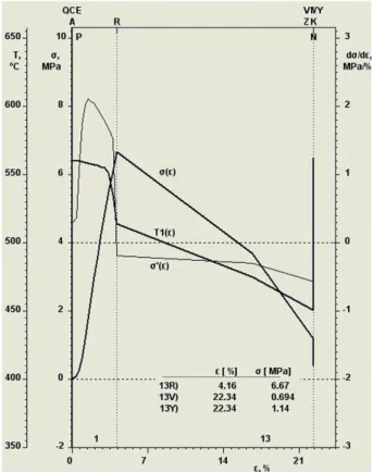
Figures 5 and 6 show changes in tensile stress (σ) and temperature in the center of the cast as a function of the relative elongation (ε) for AlSi21CuNiMg unmodified alloy (Fig. 5) and for the alloy after modification with 0.2% AlCu19P1.4 (Fig. 6). Figure 5 shows that for the unmodified alloy a stress of 3.5 MPa was obtained, corresponding to a negligible elongation.
In the case of the alloy after modification with AlCu19P1.4 master alloy in the amount of 0.2%, the tensile stress increased to 6.6 MPa (Fig. 6) with simultaneous elongation at the level of 4.16%. In the case of unmodified silumin, the structure of the alloy consists of a small eutectic mixture (αAl + βSi) and compact large crystals of primary silicon (Si). The form of the crystals of the primary silicon and their high hardness and brittleness adversely affect the mechanical properties of silumin (tensile strength). The modification with phosphorus in the form of AlCu19P1.4 master alloys resulted in fragmentation (reduction in size) and a change of the form of the crystals of the primary silicon into a com-pact form and their regular distribution in the structure of the tested alloy.
Fig. 3. Thermal-Derivative Analysis (TDA) diagram for silumin AlSi21CuNiMg without modification
Fig. 4. Thermal-Derivative Analysis(TDA) diagram for silumin AlSi21CuNiMg modified with AlCu19P1.4
Fig. 5. Silumin AlSi21CuNiMg without modification – tensile stress (σ) and temperature in the center of the cast as a function of elongation (ε)
Fig. 6. AlSi21CuNiMg silumin modified with AlCu19P1.4 master alloy – tensile stress (σ) and temperature in the center of the cast as a function of elongation (ε)
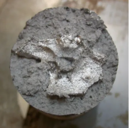
Figures 7 and 8 present the photographs of the break-through of the tested silumin in the unmodified state and after the modification with the master alloys AlCu19P1.4. Images of the fracture surface (from a scanning electron microscope) of the tested alloy samples in the unmod-ified state and after the modification with the addition of AlCu19P1.4 are shown in Figures 9–12.
Figures 9 and 10 show that in the unmodified alloy there is a transcrystalline crack in the eutectics area, by the eutec-tic phase αAl and the eutectic silicon (βSi). The crack also progressed through the crystals of the primary silicon (Si).
The breakthroughs in Figure 11 and Figure 12 for the alloy modified with AlCu19P1.4 master alloy, also show the transcrystalline nature of cracking in the eutectic area. The crystals of the primary silicon were cracking in the cleavage planes, and in a few cases remained intact (Fig. 12). These breakthroughs are characterized by a greater surface devel-opment in relation to the unmodified sample (Figs. 9 and 10).
Fig. 7. Photo of the fracture of silumin AlSi21CuNiMg without modification
Fig. 8. Photo of the fracture of silumin AlSi21CuNiMg modified with AlCu19P1.4 (0.2%)
Fig. 9. The surface of the fracture of silumin AlSi21CuNiMg without modification
Fig. 10. The surface of the fracture of silumin AlSi21CuNiMg without modification
Fig. 11. The surface of the fracture of silumin AlSi21CuNiMg modified witch AlCu19P1.4 (0.2%)
Fig. 12. The surface of the fracture of silumin AlSi21CuNiMg modified witch AlCu19P1.4 (0.2%)
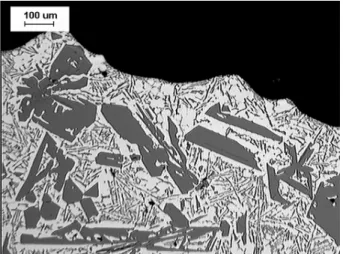
Figures 13 and 14 show the microphotographs of the sample profile (optical microscope) of the AlSi21CuNiMg alloy in the unmodified state and after modification with the addition of AlCu19P1.4 in the amount of 0.2%.
Figure 13 shows that in the structure of the tested alloy, besides the eutectic mixture (αAl + βSi) there are extensive crys-tals of the primary silicon (Si) of large size. Modification with phosphorus in the form of AlCu19P1.4 master alloy result-ed in multiple fragmentation of the crystals in the primary silicon and their more regular distribution in the structure of silumin (Fig. 14). Such a change affected the cracking
profile of AlSi21CuNiMg silumin (Fig. 14) meaning that the main crack now passes mainly through the eutectic mixture (αAl + βSi), and mostly through the brittle crystals of eutectic silicon.
4. CONCLUSIONS
Modification of the tested silumin resulted in a favorable de-fragmentation and regular distribution of the crystals of the primary silicon (Si) in the alloy structure, which as a conse-quence provided almost a twofold increase in the strength of the silumin samples in the final solidification stage from 3.5 to 6.6 MPa. This is related to a favorable change of the morphology of breakthroughs within the tested silumin samples. As a result, the resistance of silumin to hot cracks should increase, which has great applicational importance while casting the hypoeutectic silumin in a metal mould that strongly inhibits the shrinkage of the castings.
Acknowledgment
M.R.D., K.K.D., W.W. acknowledge the financial support from the program of the Polish Minister of Science and Higher Educa
-tion ”Regional Initiative of Excellence” in 2019–2022, project no. 003/RID/2018/19, funding amount 11936596.10 PLN.
REFERENCES
[1] Górny Z. (1992). Odlewnicze stopy metali nieżelaznych. War-szawa: Wydawnictwa Naukowo-Techniczne.
[2] Höner K.E. (1982). Die thermische Analyse als Kontrollver-fahren für die Wirksamkeit einer Schmelzebehandlung von Aluminium-Gusslegierungen durch Veredelung oder Kornfei-nung. Giessereiforschung, 34(1), 1–10.
[3] Pietrowski S. (2001). Siluminy. Łódź: Wydawnictwo Politech-niki Łódzkiej.
[4] Poniewierski Z. (1989). Krystalizacja, struktura i właściwości siluminów. Warszawa: Wydawnictwa Naukowo-Techniczne. [5] Velten B., Rasche C. & Herold-Schmidt U. (1989). Bildung und Ausbreitung von Thermoschockrissen in einer Aluminium- -Gusslegierungen. Practical Metallography – Special Edition, 20, 271–280.
[6] Mutwil J., Romankiewicz R. & Kujawa K. (2005). Nowa wersja stanowiska do badania wytrzymałości na rozciąganie krzep-nących metali i stopów. Archive of Foundry Engineering, 5(17), 183–190.
[7] Romankiewicz R. (2011). Badania nad możliwością szybkiej oceny właściwości technologicznych siluminów w końcowym etapie krzepnięcia i początkowym etapie stygnięcia. Doctoral Dissertation. University of Zielona Góra.
Fig. 13. Microphotography of the profile of the fracture of silumin AlSi21CuNiMg without modification
Fig. 14. Microphotography of the profile of the fracture of silumin AlSi21CuNiMg modified with AlCu19P1.4 (0.2%)
![Fig. 1. The test stand for the examination of the tensile strength of solidifying and cooling metals and alloys with testing mould [6, 7]:](https://thumb-us.123doks.com/thumbv2/123dok_us/8926901.2375974/2.892.102.402.155.511/examination-tensile-strength-solidifying-cooling-metals-alloys-testing.webp)