OSTBC Transmission in MIMO AF Relaying with
M
-FSK Modulation
Ha X. Nguyen
1, Chan Dai Truyen Thai
2, Nguyen N. Tran
31[email protected], School of Engineering, Tan Tao University Tan Duc Ecity, Duc Hoa, Long An Province, Vietnam
2[email protected], Univ Lille Nord de France
F-59000, Lille, IFSTTAR, LEOST, F-59650, Villeneuve d’Ascq, France
3[email protected], Faculty of Electronics and Telecommunications, University of Science Vietnam National University, Ho Chi Minh City, Vietnam
Abstract— This paper investigates orthogonal space-time block
coded (OSTBC) transmission for multiple-input multiple-output (MIMO) amplify-and-forward (AF) relaying networks composed of one source, K relays, and one destination and with M -ary frequency-shift-keying (FSK) modulation. A non-coherent detection scheme is proposed and analyzed in a situation where the fading channels undergo temporal correlation. Specifically, by properly exploiting the implicit pilot-symbol-assist property of FSK transmission, the destination estimates the overall channels based on the linear minimum mean square error (LMMSE) estimation algorithm. It then utilizes the maximal ratio combining (MRC) to detect the transmitted information. An upper bound on the probability of errors is derived for a network with arbitrary numbers of transceiver antennas and relays. Based on the obtained bit-error-rate, the full achievable diversity order is verified. Simulation results are presented to show the validity of the analytical results.
I. INTRODUCTION
Noncoherent transmission techniques have received a lot of attention due to their potential improvement in complexity by elimating the need of channel state information at the receiver. Consequently, employing those non-coherent techniques is preferable in wireless relay networks since there are many wireless fading channels involved in the networks [1], [2], which makes the task of channel estimation very complex and expensive to implement.
In recent years, much more research works has focused on non-coherent wireless relay networks [3]–[10], i.e., the wireless relay networks in which channel state information (CSI) is assumed to be unknown at the receivers (relays and destination). Among them, non-coherent amplify-and-forward (AF) has received more attention since it further puts a less processing burden on the relays due to the AF protocol [3]–[10]. However, only suboptimal non-coherent AF receivers have been studied due to the complicated deployment in practice [5], [8]. Especially, when the channels undergo temporally-correlated Rayleigh flat fading, reference [9] is the only work to develop a detection scheme for non-coherent amplify-and-forward (AF) relay networks. It would be em-phasized that all the above-mentioned works assume that all nodes in the network are equipped with a single antenna.
Multiple-input multiple-output (MIMO) relaying tech-niques, that use multiple antennas at all nodes in the network,
have been known to improve considerably performance in terms of data transmission rates as well as reliablity over wireless channels. However, most existing works assume the availability of CSI of all the transmission links propagated by the received signals at the receivers to perform a detection [11]. Hence, non-coherent MIMO relaying networks are studied in this paper to make the MIMO relaying techniques more applicable. In fact, the work in [12] preliminarily develops a detection framework for multi-antenna AF relay networks. However, the work only considers a special network in which the source is equipped with two transmit antennas, the multiple relays and destination are equipped with a single antenna and an Alamouti space-time block code is employed.
This work studies a more generalized multi-antenna AF relay network, i.e., all the nodes in the network are equipped with multiple antennas. OSTBC is employed at the source to transmit a signal to the destination. Basically, the technique employed in this work is similar in [9], [12]. By using the linear minimum mean square error (LMMSE) estimation algorithm, the destination first estimates the overall channels based on the pilot symbol inherent in FSK transmission. Then it employs the maximal ratio combining (MRC) to detect the transmitted information. The main contribution of this paper is to develop a general framework for a network with arbi-trary numbers of nodes and arbiarbi-trary numbers of transceiver antennas equipped at each node. Moreover, a unified upper-bound BER expression is derived. It is further shown that the proposed detection scheme achieve a full diversity order.
II. SYSTEMMODEL
Consider a wireless relay network in which the source, de-noted by node0, communicates with the destination, denoted by nodeK+ 1, with the assistance of K half-duplex relays, denoted by node i, i = 1, . . . , K. It is assumed that the K
broadcasts an OSTBC designed forN0 antennas to the relays and destination. In the second phase, i.e., the nextPKi=1NiTc
time slots1, the relays amplify the received signals and forward to the destination. The destination then estimate the overall channels of all the links from the source to the destination and performs a MRC withPKi=1Ni+ 1NK+1Tc received signals for the final detection decision based on the estimated overall channels.
For convenience, let us adopt the convention that epoch
k is a period of time to complete a signal transmission from the source to the destination. With the above-mentioned transmission protocol, epoch k starts at t = k(PKi=1Ni+ 1)TcT and ends at(k+ 1)(PKi=1Ni+ 1)TcT whereT is the symbol duration (or time slot duration). The channel fading coefficient between the mth transmit antenna of node i and the nth receive antenna of nodej at epochk is denoted by
hm,ni,j [k]. Those channel coefficients are modeled as circularly symmetric complex Gaussian random variables and assumed to be constant over (PKi=1Ni+ 1)Tc time slots but varies
dependently every period of(PKi=1Ni+ 1)Tctime slots. The temporally-correlated fading environment is modeled with the following Jake’s autocorrelation
φm,ni,j [p] = σi,jm,n2J0 2πfi,jm,np (1) wherefi,jm,nand σi,jm,n2are the maximum Doppler frequency and the average signal strength of the channel corresponding the connection between the mth transmit antenna of node i
and the nth receive antenna of nodej, respectively.
The received signal during thelth (l= 1, . . . , Tc) time slot of the first phase at thenth antenna of nodej,n= 1, . . . , Ni,
j = 1, . . . , K+ 1, at epochk is written as
yn,l0,j(t) = r
E0 N0
N0
X
m=1
hm,n0,j [k]xlj(t) +w n,l
0,j(t), t∈Tk,l (2)
whereTk,l=
h
k(PK
i=1Ni+ 1)TcT + (l−1)T, k( PK
i=1Ni+ 1)TcT +lT) denotes the interval of time slot l of epoch k,wn,l0,j(t) is zero-mean additive white Gaussian noise (AWGN) at the nth antenna of node j with two-sided power spectral density (PSD) of M0/2 during thelth time slot. In the above expression,E0represent the average symbol energy available at the source andxl
j(t)is the transmitted waveform sent from
the jth antenna of node 0 during time slot l. This waveform is chosen from an M-ary FSK constellation and therefore is written in complex baseband as
xl j(t) =
1 √
T exp
iπt
T (2m−M −1)
, m= 1, . . . , M
The following amplifying factor is chosen at thenth antenna of relay node j before retransmitting:
βjn = s
Ej/Nj
E0/N0PN0
m=1 σ m,n 0,j
2
+M0, (3)
1Without loss of generality, the orthogonal channels are assumed to be made by means of time-division multiplexing.
whereEj is the average transmitted symbol energy allocated to node j. The received signal at the gth antenna of the destination via the nth antenna of relay node j at epoch k, i.e., during the time interval t ∈ Tk,l, l = Tc + 1, Tc +
2, . . . ,(PKi=1Ni+ 1)Tc, can be written as
yj,Kn,g,l+1(t) =
N0
X
m=1 βn
j p
E0hm,n,g0,j,K+1[k]xl−( Pj−1
i=1Ni+1)Tc j (t−
(l−(
j−1 X
i=1
Ni+ 1)Tc)T) +w0,j,K+1n,g,l (t), (4)
wherehm,n,g0,j,K+1[k] =hm,n0,j [k]hn,gj,K+1[k]is the overall channels from themth antenna of the source to thegth antenna of the destination via thenth antenna of nodejat epochk. The
wave-formw0,j,K+1n,g,l (t) =βn jh
n,g j,K+1[k]w
n,l−(Pj−1
i=1Ni+1)Tc
0,j (t−(l−
(Pj−1
i=1Ni+ 1)Tc)T) +w g,l
j,K+1(t) is the total additive noise
corrupting the received signal. The noisewj,Kg,l +1(t)is also a zero-mean AWGN with two-side PSD ofM0/2.
III. DATADETECTION
A. Channel Estimation
The destination correlates the received signals in (2) and (4) with the following sum waveformr(t)to estimate the overall channels [9], [13]:
r(t) =
M
2
X
l=1
2 √
T cos
(2l−1)πt
T
(5)
The output of the correlators can be stacked and re-organized as2
y0,K+1(E) =
r E0 N0X
(E)
0,K+1h0,K+1+ w(E)0,K+1,
y(E)j,K+1=
r E0 N0X
(E)
j,K+1h0,j,K+1+ w(E)j,K+1, j= 1, . . . , K
where the channel vectors h0,K+1 ∈ CN0NK+1×1 and
h0,j,K+1∈CN0NjNK+1×1 are
h0,K+1=
h1,10,K+1 · · · hN0,1
0,K+1 · · · h
N0,NK+1
0,K+1 t
,
h0,j,K+1=
h1,1,10,j,K+1 · · · h N0,1,1
0,j,K+1 h 1,1,2
0,j,K+1 · · · hN0,1,NK+1
0,j,K+1 h 1,2,1
0,j,K+1 · · · h
N0,Nj,NK+1
0,j,K+1 t
.
The noise vectors w(E)0,K+1 ∈ CNK+1Tc×1 and w(E) j,K+1 ∈
CNjNK+1Tc×1 are
w(E)0,K+1=
w0,K+11,1 · · · w1,Tc
0,K+1 · · · w NK+1,Tc 0,K+1
t ,
w(E)j,K+1= w1,1,1j,K+1 · · · w1,1,Tc j,K+1 w
1,2,1 j,K+1 · · · w1,NK+1,Tc
j,K+1 w 2,1,1
j,K+1 · · · w
Nj,NK+1,Tc j,K+1
t .
Meanwhile, the signal vectors y(E)0,K+1 ∈ CNK+1Tc ×1 and
yj,K(E)+1∈CNjNK+1Tc ×1are
y(E)0,K+1= y1,10,K+1 · · · y1,Tc
0,K+1 · · · y NK+1,Tc 0,K+1
t ,
y(E)j,K+1=
yj,K+11,1,1 · · · y1,1,Tc j,K+1 y
1,2,1 j,K+1 · · · y1,NK+1,Tc
j,K+1 y 2,1,1
j,K+1 · · · y
Nj,NK+1,Tc j,K+1
t .
On the other hand, X0,K+1(E) and X (E)
j,K+1 are defined as two NK+1 and NjNK+1 block diagonal matrices, respectively, i.e.,
X0,K+1(E) = diag{X, X, . . . , X
| {z }
NK+1elements },
Xj,K+1(E) = diag{β1jX, . . . , βj1X
| {z }
NK+1elements
, . . . , βNj
j X, . . . , β Nj j X},
where blockX is theTc×N0matrix code with the elements of 1 or −1. For example, if an Alamouti code is employed at
the source, then X =
1 1
−1 1
.
Using LMMSE estimators, the LMMSE estimations of h0,K+1[k] andh0,i,K+1[k]can be obtained as follows [14]:
ˆ
h0,K+1= Ψh
0,K+1y(0E,K)+1
Φy(E) 0,K+1y
(E) 0,K+1
−1
y(E)0,K+1
ˆ
h0,j,K+1= Ψh
0,j,K+1y(0E,j,K) +1
Φy(E) 0,j,K+1y
(E) 0,j,K+1
−1
y(E)0,j,K+1.
In the above expressions, y(E)0,K+1 ∈ C(2P+1)NK+1Tc ×1 and
y(E)0,j,K+1 ∈ C(2P+1)NjNK+1Tc×1, j = 1, . . . , K, are formed
by stacking 2P + 1 consecutive vectors y(E)0,K+1[k+l] and y0,j,K+1(E) [k+l],l =−P, . . . , P, respectively. Ψhy(E) denotes
the correlation matrix between h and y(E). Φy(E)y(E) is the
auto-correlation matrix of y(E). As mentioned in [9], there
is a trade-off between complexity and performance, i.e., in-creasing P may improve the performance but also increase the complexity.
The matricesΨh
0,K+1y(0E,K)+1
andΨh
0,j,K+1y(0E,j,K) +1
are com-puted, respectively, as follows
Ψh
0,K+1y(0E,K)+1 =
r E0
N0(Θ0,K+1[k−P]
Θ0,K+1[k−P+ 1] . . . Θ0,K+1[k+P]), (6)
Ψh
0,j,K+1y(0E,j,K) +1=
r E0
N0(Θ0,j,K+1[k−P]
Θ0,j,K+1[k−P+ 1] . . . Θ0,j,K+1[k+P]), (7)
where
Θ0,K+1[l] = diag n
φ1,10,K+1[l], φ2,10,K+1[l], . . . , φN0,NK+1
0,K+1 [l] o
X0,K+1(E) t, (8)
Θ0,j,K+1[l] = diag n
φ1,1,10,j,K+1[l], . . . , φ N0,1,1
0,j,K+1[l], . . . , φN0,NjNK+1
0,j,K+1 [l] o
X0,j,K+1(E) t, (9) whereφm,n,g0,j,K+1[l]is the auto-correlation function of the overall channelhm,n,g0,j,K+1. One has
φm,n,g0,j,K+1[l] =σm,n0,j σj,K+1n,g 2
J0 2πf0,jm,nl
J02πfj,K+1n,g l
Meanwhile, the matrices Φy(E) 0,K+1y
(E) 0,K+1
and Φy(E)
0,j,K+1y (E) 0,j,K+1
can be presented as
Φy(E) 0,K+1y
(E)
0,K+1 =
h
(S0,K+1)p,q i
(2P+1)×(2P+1) and
Φy(E) 0,j,K+1y
(E)
0,j,K+1 =
h
(S0,j,K+1)p,q i
(2P+1)×(2P+1) where
(S0,K+1)p,q =
diagnΛ1
0,K+1,Λ20,K+1, . . . ,Λ NK+1
0,K+1 o
p,q
,
(S0,j,K+1)p,q=
diagnΛ1
0,j,K+1,Λ20,j,K+1, . . . ,Λ NK+1
0,j,K+1 o
p,q
where
Λg0,K+1
p,q and
Λg0,j,K+1
p,q are computed as (24)
and (25).
The estimation errorse0,K+1[k] = h0,K+1[k]−ˆh0,K+1[k]
and e0,j,K+1[k] = h0,j,K+1[k]−hˆ0,j,K+1[k] are zero-mean
with covariance matrices given as [14]
Ce0,K+1e0,K+1=Ch0,K+1h0,K+1 −Ψh
0,K+1y(0E,K)+1
Φy(E) 0,K+1y
(E) 0,K+1
−1
ΨH
h0,K+1y(0E,K)+1
(27)
Ce0,j,K+1e0,j,K+1=Ch0,j,K+1h0,j,K+1 −Ψh
0,j,K+1y(j,KE)+1
Φy(E)
j,K+1y (E)
j,K+1
−1
ΨHh
0,j,K+1y(j,KE)+1
. (28)
It is clear that Ce0,K+1e0,K+1 and Ce0,j,K+1e0,K+1 are
diagonal matrices. Let eσ0,K+1m,n 2 and eσ0,j,K+1m,n,g 2
be the variances of the estimation errors em,n0,K+1[k] = hm,n0,K+1[k] − ˆhm,n0,K+1[k] and em,n,g0,j,K+1[k] = hm,n,g0,j,K+1[k] − ˆ
hm,n,g0,j,K+1[k], respectively, one has eσ0,K+1m,n 2 =
Ce0,K+1e0,K+1
(n−1)N0+m,(n−1)N0+m and
e
σm,n,g0,j,K+12 =
Ce0,j,K+1e0,j,K+1
((n−1)NK+1+(g−1))N0+m,((n−1)NK+1+(g−1))N0+m
where[A]i,i represents theith diagonal element of matrixA.
B. Data Detection
The destination correlates the received waveforms in (2) and (4) with the following vector x(t) to detect the transmitted data:
x(t) = x∗
1(t) x∗2(t) . . . x∗M(t) t
. (29)
The outputs of the correlators can be written as
yn,l0,K+1[k] =
r E0 N0
N0
X
m=1
ˆ
hm,n0,K+1[k] +em,n0,K+1[k]xl m[k]
Λg0,K+1
p,q=Xdiag
E0
N0φ 1,g
0,K+1[p−q], . . . , E0 N0φ
N0,g
0,K+1[p−q]
Xt+M N0δ[p
−q]IN0×N0, (24)
Λg0,j,K+1
p,q= diag
Λ1,g0,j,K+1
p,q,
Λ2,g0,j,K+1
p,q, . . . ,
ΛNj,g 0,j,K+1 p,q , (25)
Λn,g0,j,K+1
p,q=Xdiag
βjn 2E0
N0φ 1,n,g
0,j,K+1[p−q], . . . , βnj 2 E0
N0φ N0,n,g
0,j,K+1[p−q]
Xt
+βn
jσ n,g j,K+1
2
M N0δ[n−m] +M N0δ[p−q]
IN0×N0, g= 1, . . . , NK+1 andn= 1, . . . , Nj. (26)
yn,g,lj,K+1[k] = N0
X
m=1 βjn
r E0 N0
ˆ
hm,n,g0,j,K+1[k] +e m,n,g 0,j,K+1[k]
xlm[k]
+ wn,g,l0,j,K+1[k], (31) wherexl
m[k]is the M×1 vector that represents the transmit
symbol from the mth antenna of node 0 at epoch k. Note thatxl
m[k]has 1 at an element and 0 at others. The elements
of noise vectors wn,l0,j[k] and w0,j,K+1n,g,l [k] with size M ×1 are i.i.d. zero-mean random variables with variance M0 and
(βn iσ
n,g
j,K+1)2+ 1
M0, respectively.
By using the property of complex orthogonal designs, one can stack and rewrite the input/output relations as
y1 0,K+1 y2 0,K+1 · · · yNK+1
0,K+1 = r E0 N0 ˆ H1 0,K+1 ˆ H20,K+1
· · · ˆ HNK+1
0,K+1 x + r E0 N0
E10,K+1
E2 0,K+1
· · · ENK+1
0,K+1 x+
w10,K+1
w2 0,K+1
· · · wNK+1
0,K+1 , (32)
y0,j,K+1n,1
y0,j,K+1n,2 · · · yn,NK+1
0,j,K+1 =β
n j r E0 N0 ˆ Hn,10,j,K+1
ˆ Hn,20,j,K+1
· · · ˆ Hn,NK+1
0,j,K+1 x
+βnj r E0 N0
En,10,j,K+1 En,20,j,K+1
· · · En,NK+1
0,j,K+1 x+
w0,j,K+1n,1 w0,j,K+1n,2
· · · wn,NK+1
0,j,K+1 , (33)
where y0,K+1g = ˜yg,10,K+1 . . . ˜yg,Tc 0,K+1
t
∈ CM Tc×1
and yn,g0,j,K+1 =
˜
yn,g,10,j,K+1 . . . ˜yn,g,Tc 0,j,K+1
t
∈ CM Tc×1, g = 1, . . . , NK+1, represent the output of the correlators at the gth antenna of the destination. Similarly, wg0,K+1 =
˜
wg,10,K+1 . . . w˜g,Tc 0,K+1
t
∈CM Tc×1 and
wn,g0,j,K+1 = w˜n,g,10,j,K+1 . . . w˜ n,g,Tc 0,j,K+1
t
∈ CM Tc×1 are
the noise vectors. Note that y˜g,l0,K+1 = y g,l
0,K+1 ory˜ g,l 0,K+1 =
y0,K+1g,l
∗
depends on the structure of OSTBCs. It is similar
to ˜yn,g,l0,j,K+1,˜eg,l0,K+1 and ˜en,g,l0,j,K+1. Hˆg0,K+1 (or Eg0,K+1) and ˆ
Hn,g0,j,K+1 (or E n,g
0,j,K+1) denote the M Tc ×M C matrices
containing estimated channel gains (or channel estimation errors). Note that the matrices are uniquely obtained from any OSTBC.
The vector x[k] is defined as x[k] = x1[k] . . . xC[k]
t
where xc[k], c = 1, . . . , C is
the M ×1 vector that represents the cth data symbol that enter the OSTBC encoder at epoch k. Note thatxc[k] is an
unit vector.
Giving the estimated (overall) channels, the maximum SNR detector at the destination is of the following form
r[k] =
NXK+1
g=1
εg0,K+1Hbg0,K+1H[k]y0,K+1g [k]+
K X
j=1 NXK+1
g=1 Nj X
n=1 εn,gj,K+1
b
Hn,g0,j,K+1H[k]yn,gj,K+1[k], (34)
where the combining weights are
εg0,K+1 = E0
N0 N0 X m=1 e
σm,g0,K+12+N0M0 !−1
(35)
εn,gj,K+1=
βn j 2 E0 N0 N0 X m=1 e
σ0,j,K+1m,n,g 2
+N0 βn
j 2
σn,gj,K+12M0+N0M0 −1
(36)
Finally, due to the orthogonal property of OSTBCs, the transmitted symbols are decided by
( ˆm,ˆxc[k]) = arg max
m=1,...,MRe(rm+cM[k]), c= 1, . . . , C
(37) whereri[k]is theith element of theM C×1vectorr[k].ˆxc[k]
is aM×1unit vector with 1 at themth element, i.e., thecth transmit waveform that enter the OSTBC encoder is decoded as using themthM-FSK tone’s frequency.
IV. UPPERBOUND ONBER PERFORMANCE AND
DIVERSITYORDER
output can be written as
γ=
NXK+1
g=1
ˆ
γ0,K+1g +
K X
j=1 Nj X
n=1
ˆ
γj,K+1n (38)
where
ˆ
γg0,K+1=
E0
N0
εg0,K+1 N0 X
m=1
ˆ
hm,g0,K+1
2!
(39)
ˆ
γj,Kn +1= NK+1
X
g=1
E0
N0
βjn
2
εn,gj,K+1 N0 X
m=1
ˆ
hm,n,g0,j,K+1
2!
(40)
To simplify our analysis, we assume that BFSK is employed at the source, i.e., M = 2 and the average signal strength between any two antennas of two particular nodes is iden-tical, i.e., σi,jm,n2 = (σi,j)2, i = 1, . . . , K. It means that the average signal strength between any two antennas of the source-destination link via a relay is also identical, i.e.,
σm,n,g0,j,K+12= (σ0,j,K+1)2. The MGF ofγˆ0,K+1g is
Mˆγg0,K+1(s) =
1 + E0
N0 σ 2
0,K+1−σe20,K+1
εg0,K+1s −N0
.
(41) Meanwhile, the MGF ofˆγn
j,K+1can be computed as Appendix
I. Since γˆ0,K+1g and ˆγn
j,K+1 are statistically independent,
the average BER for the OSTBC with BFSK in MIMO-AF relaying can be upper-bounded as
Pe≤ 1 π
Z π
2
0 Mγ
g
sin2θ
dθ= 1
π Z π
2
0 NYK+1
g=1
Mγˆg0,K+1(s)
g
sin2θ
j=K,n=NY j
j=1,n=1 Mγˆn
j,K+1(s)
g
sin2θ
dθ (42)
whereg= 1
2 for BFSK. One can obtain an upper-bound BER
expression of the network by substituting (41) and the result from Appendix I into (42). Under the high SNR assumption,
e σ2
0,K+1 (i = 0, . . . , K), and σe20,j,K+1 (i = 1, . . . , K)
approach 0. It then can be verified that a maximum diversity order ofN0NK+1+max{N0, NK+1}KPKj=1Njis achieved.
V. SIMULATIONRESULTS
In conducting the simulations, it is assumed that the source and relays have an equal transmit power, i.e., Ei =E, i = 0, . . . , K. The noise components at the receivers, i.e., relays and destination are modeled as i.i.d. CN(0,1) random vari-ables. The path-loss follows the exponential-decay model, i.e.,
σ(k)i,j2=d−ν
i,j wheredi,jis the distance between nodeiand
node j. All the simulations are reported with the path loss exponentν= 4. In addition, all the relays are assumed to have the same distances to the source and to the destination, i.e.,
d0,1 =d0,2 =· · · =d0,K =d1,d1,K+1 =d2,K+1 =· · · =
dK,K+1=d2, andd0,K+1=d0. The Doppler frequencies are set as10f0,iT =fi,K+1T =f0,K+1T = 0.01,i= 1, . . . , K. BFSK modulation is employed at the source.
0 4 8 12 16 20
10−6
10−5
10−4
10−3
10−2
10−1
100
Average Power per Node (dB)
BER
Coherent
Proposed (simulation), P = 0 Proposed (upper−bound), P = 0 Proposed (simulation), P = 2 Proposed (upper−bound), P = 2
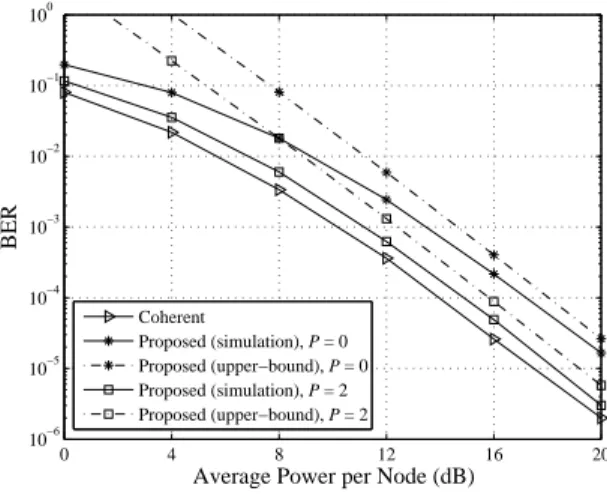
Fig. 1. Error performance of a single-relay network with Alamouti space-time code whenM = 2(BFSK),N0 = 2,N1 =N2 = 1(the source is
equipped with two antennas, the relay and destination are equipped with a single antenna),d0= 0.8, d1= 1, d2= 1.
Fig. 1 shows the average BER of the proposed scheme by simulation for a single relay network. In this setup, the source is equipped with two antennas, the relay and destination are equipped with a single antenna. Naturally, an Alamouti space-time block code is used at the source. One can observe the tightness of the derived upper-bound BER of the proposed scheme. Also, the diversity order of 3 is confirmed3.
0 4 8 12 16
10−8
10−6
10−4
10−2
100
Average Power per Node (dB)
BER
Coherent
Proposed (simulation), P = 0 Proposed (simulation), P = 1 Proposed (simulation), P = 2 Proposed (simulation), P = 3 Proposed (simulation), P = 4
Fig. 2. Error performance of a single-relay network with orthogonal space-time code whenM = 2(BFSK),N0 = 3,N1 =N2 = 2(the source is equipped with three antennas, the relay and destination are equipped with two antennas),d0= 1, d1= 0.5, d2= 1.5.
The BER performance of the proposed scheme and the coherent scheme is illustrated in Fig. 2 for the case of a single-relay network in which the source is equipped with three antennas, the relay and destination are equipped with two antennas. The orthogonal space-time code for three transmit
antennas is employed at the source. In this simulation, the relays are placed close to the source. The figure again confirms that one can get the estimations of the (overall) channels in MIMO AF relaying networks employed M-FSK modulation without the explicit pilot symbols to perform a detection. Note that the performance gap to the coherent scheme of the proposed scheme becomes smaller when P increases.
VI. CONCLUSION
A detection scheme for multiple-input multiple-output (MIMO) amplify-and-forward (AF) relaying networks has been proposed. The investigated networks compose of one source,K relays, and one destination. Orthogonal space-time block code (OSTBC) is employed at the source together with
M-ary frequency-shift-keying (FSK) modulation to transmit the signals to the destination. By using the orthogonal property of FSK signalling, we have discussed an overall channel estimation method without the explicit pilot symbols. With the estimated overall channels, a maximal ratio combiner is employed to detect the transmitted information. An upper-bound expression on the probability of errors is obtained for a general network with K relays and arbitrary numbers of transceiver antennas at the source, relays, and destination. In addition, we have derived that the proposed detection scheme can achieve a full diversity order. Simulation results are also presented to validate the analytical results.
APPENDIXI
DERIVATION OFMGFOFˆγnj,K+1IN(40)
Let Y = PNK+1
g=1 PN0
m=1
ˆhm,n,g0,j,K+1 2
=
PN0
m=1
ˆhm,n0,j 2 PNK+1
g=1
ˆhn,gj,K+12
= X1X2 where
X1 = PN0
m=1
hˆm,n0,j 2 and X2 = PNK+1
g=1
ˆhn,gj,K+12. Due to the fact that
ˆhm,n0,j and
ˆhn,gj,K+1 are the estimates of
hm,n0,j and
hn,gj,K+1, one can approximate that the pdfs of
ˆhm,n0,j and
ˆhn,gj,K+1 have the same form as the pdfs of hm,n0,j and
hn,gj,K+1, respectively. Since hm,n0,j and
hn,gj,K+1 are Rayleigh distributed, the pdfs of
hˆm,n0,j
and
hˆn,gj,K+1 can be approximated as f
|ˆhm,n
0,j |
2(x) = 1
ˆ σ2
0,j
e−
x
ˆ
σ02,j
and f
|hˆn,g j,K+1|
2(x) = 1
ˆ σ2
j,K+1e
− x
ˆ
σj,K2 +1
, respectively. It is clear that
fX1(x) =
xN0−1e− x
ˆ
σ20,j
(ˆσ0,j)2N0
Γ(N0), (43)
fX2(x) =
xNK+1−1e− x
ˆ
σ2j,K+1
(ˆσj,K+1)2NK+1Γ(NK+1) (44)
The MGF ofY can then be computed as follows:
Case 1 (N0> NK+1):
MY(s) =
Z ∞
0
fX1(x)MX2(sx)dx
≃ Z ∞
0
xN0−NK+1−1e− x
ˆ
σ02,j
Γ(N0) (ˆσ0,j)2N0
1
(ˆσj,K+1)2NK+1sNK+1dx
=Γ(N0−NK+1)(ˆσ
2
0,j)N0−NK+1
Γ(N0)(ˆσ2 0,j)N0σˆ
2NK+1
j,K+1s
= Γ(N0−NK+1)
Γ(N0)ˆσ2NK+1
0,j,K+1s Case 2 (N0< NK+1): Similar to Case 1, butN0andNK+1
are interchanged.
Case 3 (N0=NK+1):
MY(s) =
Z ∞
0
xNK+1−1e− x
ˆ
σ2j,K+1
Γ(NK+1) (ˆσj,K+1)2NK+1
1 (1 + ˆσ2
0,jsx)N0
dx
≃ Z ∞
q
e
q
ˆ
σ2j,K+1 p−1e−
p
ˆ
σj,K2 +1
Γ(NK+1) (ˆσ0,j,K+1)2NK+1
sNK+1dp
≤ log ˆσ
2 0,j,K+1
Γ(NK+1) (ˆσ0,j,K+1)2NK+1sNK+1
REFERENCES
[1] A. Sendonaris, E. Erkip, and B. Aazhang, “User cooperation diversity, Part I: System description,” IEEE Trans. Commun., vol. 51, no. 11, pp. 1927–1938, November 2003.
[2] J. Laneman, D. Tse, and G. Wornell, “Cooperative diversity in wireless networks: Efficient protocols and outage behavior,” IEEE Trans. Inform. Theory, vol. 50, pp. 3062–3080, December 2004.
[3] T. Himsoon, W. Pam Siriwongpairat, W. Su, and K. Liu, “Differential modulations for multinode cooperative communications,” IEEE Trans. Signal Process., vol. 56, pp. 2941–2956, July 2008.
[4] Q. Zhao and H. Li, “Differential modulation for cooperative wireless systems,” IEEE Trans. Signal Process., vol. 55, pp. 2273–2283, May 2007.
[5] R. Annavajjala, P. Cosman, and L. Milstein, “On the performance of optimum noncoherent amplify-and-forward reception for cooperative diversity,” Proc. IEEE Military Commun. Conf., pp. 3280–3288, October 2005.
[6] Y. Zhu, P.-Y. Kam, and Y. Xin, “Non-coherent detection for amplify-and-forward relay systems in a Rayleigh fading environment,” Proc. IEEE Global Telecommun. Conf., pp. 1658–1662, November 2007. [7] M. R. Souryal, “Non-coherent amplify-and-forward generalized
like-lihood ratio test receiver,” IEEE Trans. Wireless Commun., vol. 9, pp. 2320–2327, July 2010.
[8] G. Farhadi and N. Beaulieu, “A low complexity receiver for noncoher-ent amplify-and-forward cooperative systems,” IEEE Trans. Commun., vol. 58, pp. 2499–2504, September 2010.
[9] H. Nguyen, H. Nguyen, and T. Le-Ngoc, “Amplify-and-forward relaying with M-FSK modulation and coherent detection,” IEEE Trans. Com-mun., vol. 60, no. 6, pp. 1555–1562, 2012.
[10] P. Liu, S. Gazor, I. Kim, and D. Kim, “Noncoherent amplify-and-forward cooperative networks: Robust detection and performance analysis,” to appear in IEEE Trans. On Communications.
[11] S. Muhaidat, J. Cavers, and P. Ho, “Transparent amplify-and-forward relaying in MIMO relay channels,” IEEE Trans. Wireless Commun., vol. 9, pp. 3144–3154, October 2010.
[12] H. Nguyen, H. Nguyen, and T. Le-Ngoc, “Wireless relay networks with alamouti space-time code and M-FSK modulation,” in 2012 Fourth International Conference on Communications and Electronics (ICCE), pp. 161–165, 2012.
[13] P. Ho, Z. Songhua, and K. P. Yuen, “Space-time FSK: An implicit pilot symbol assisted modulation scheme,” IEEE Trans. Wireless Commun., vol. 6, pp. 2602–2611, July 2007.