Image Forensic Analyses that Elude the
Human Visual System
Hany Farid
aand Mary J. Bravo
b aDepartment of Computer Science, Dartmouth College, Hanover NH 03755, USA
bPsychology Department, Rutgers University, Camden, NJ 08102, USA
ABSTRACT
While historically we may have been overly trusting of photographs, in recent years there has been a backlash of sorts and the authenticity of photographs is now routinely questioned. Because these judgments are often made by eye, we wondered how reliable the human visual system is in detecting discrepancies that might arise from photo tampering. We show that the visual system is remarkably inept at detecting simple geometric inconsistencies in shadows, reflections, and perspective distortions. We also describe computational methods that can be applied to detect the inconsistencies that seem to elude the human visual system.
Keywords: Photo Forensics
1. INTRODUCTION
In an attempt to quell rumors regarding the health of North Korea’s leader Kim Jong-Il, the North Korean gov-ernment released a series of photographs in the Spring of 2008 showing a healthy and active Kim Jong-Il. Shortly after their release theBBC∗ andUK Times† reported that the photographs might have been doctored. One of
the reported visual discrepancies was a seemingly incongruous shadow. Because such claims of inauthenticity are often made by eye, we wondered how reliable the human visual system is in detecting discrepancies that might arise from photo tampering.
In many ways, the visual system is remarkable, capable of hyperacuity,1 rapid scene understanding,2 and robust face recognition.3 In other arenas, however, the visual system can be quite inept. For example, the visual system can be insensitive to inconsistencies in lighting,4 viewing position,5 and certain judgments of lightness and color.6 There is also some evidence that observers cannot reliably interpret shadows,7 reflections,8 and perspective distortion.9 These last three cues can provide evidence of photo-tampering, and so, as the example above illustrates, it is important to understand how well observers can utilize these cues. Here we report three experiments that compare the performance of human observers with that of computational methods in detecting inconsistencies in shadows, perspective and reflections.
2. SHADOWS
2.1 Human Performance
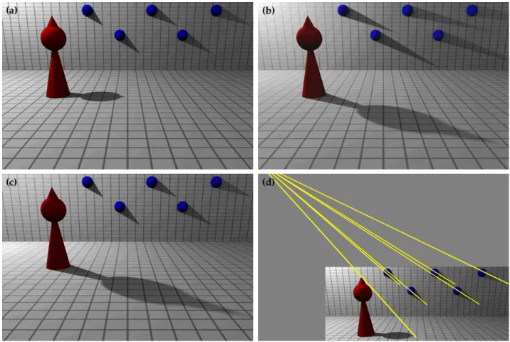
Figure 1(a) is a rendered 3-D scene illuminated by a single light that produces cast shadows on the ground plane and back wall. Panel (b) of this figure is the same scene with the light moved to a different location. Panel (c) is a composite created by combining the back wall from panel (a) and the ground plane from panel (b) to create a scene with shadows that are inconsistent with a single light. One hundred and forty rendered scenes were created such that the cast shadows were either consistent or inconsistent with a single light. For the consistent scenes, the light was positioned either on the left or right side of the room and in one of nine different locations that varied in distance from the ground plane and from the back wall. For the inconsistent scenes, the back walls from scenes with different lighting were interchanged. Twenty observers were each given unlimited time to judge whether the original and composite scenes were consistent with a single light. Their performance was
Contact: [email protected] and [email protected]
∗“’Fake photo’ revives Kim rumours”, BBC, November 12, 2008
Figure 1. The cast shadows in panels (a) and (b) are consistent with a single light. The scene in panel (c) is a composite of the back wall from panel (a) and the ground plane from panel (b). In this case, the cast shadows are inconsistent with a single light. The yellow lines in panel (d) connect points on each object to their projected shadow. The intersection of these lines is the 2-D location of the light.
nearly perfect (95.5%) for inconsistent scenes that were the combination of lights from opposites sides of the room (i.e., the cast shadows ran in opposite directions). For all other cases, however, observer accuracy was near chance (52.8%). The average response time was 4.9 seconds, indicating that observers spent a reasonable amount of time inspecting each scene.
2.2 Geometry of Shadows
Although observers have considerable difficulty detecting inconsistencies in cast shadows, there is a simple image-based technique for making this judgment. Since light travels in a straight line, a point on the shadow, its corresponding point on the object, and the light source all lie on a single line. Therefore, the light source will always lie on a line that connects every point on a shadow with its corresponding point on an object, regardless of scene geometry. In an image, the projection of these lines will always intersect at the 2-D projection of the light position.
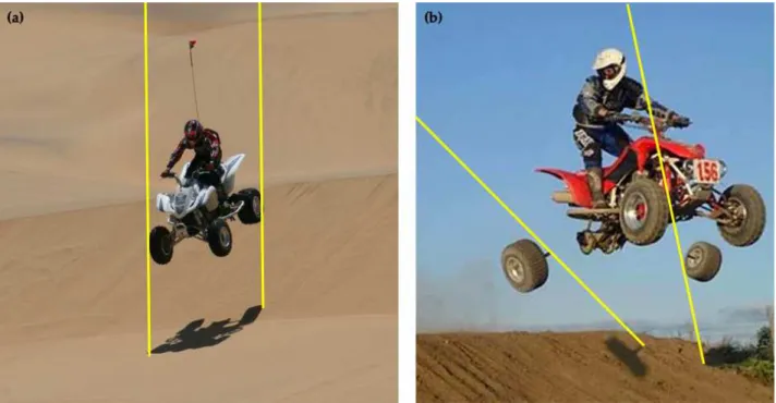
In practice, there are some limitations to this geometric analysis of light position. Care must be taken to select appropriately matched points on the shadow and the object; this is best achieved when the object has a distinct shape (e.g., the tip of a cone). If the dominant light is the sun, then the lines may be nearly parallel, making the computation of their intersection vulnerable to numerical instability. For example, Figure 2(a) is an authentic image where the sun is directly above the vehicle. The yellow lines, connecting shadow and object, are nearly parallel, making it difficult to determine if these lines intersect at a single point. On the other hand, the image in Figure 2(b) must be a fake because the lines clearly diverge. Even if the intersection is difficult to
Figure 2. An (a) authentic and (b) fake image. The yellow lines, connecting shadow and object, should intersect at the location of the light. The diverging lines on the right reveal that the cast shadows are inconsistent with a single light.
compute, this analysis can still be employed to determine if an object’s shadow is inconsistent with a single light. We also note that this simple geometric analysis could be used to condition the estimation of light direction as described in.12, 13
3. PLANAR PERSPECTIVE
3.1 Human Performance
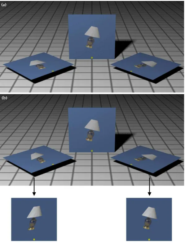
Figure 3(a) is a rendered scene with three planar surfaces texture-mapped with the same 2-D image. Panel (b) of this figure is the same scene with the texture map on the left-most panel skewed relative to the central panel. Three planar surfaces were placed in the configuration shown in Figure 3, with only one of the three planes texture-mapped with one of six images of familiar objects. The image was texture-mapped with no distortion or with horizontal skew. The horizontal skew was created by applying the affine matrix [1s; 0 1] to the image, where the amount of skewsvaried from±2 to ±8. For the left plane in Figure 3, a negative skew counteracted some of the perspective planar distortion, while a positive skew exaggerated the perspective distortion. On the other hand, a positive skew would have exaggerated the perspective distortion.
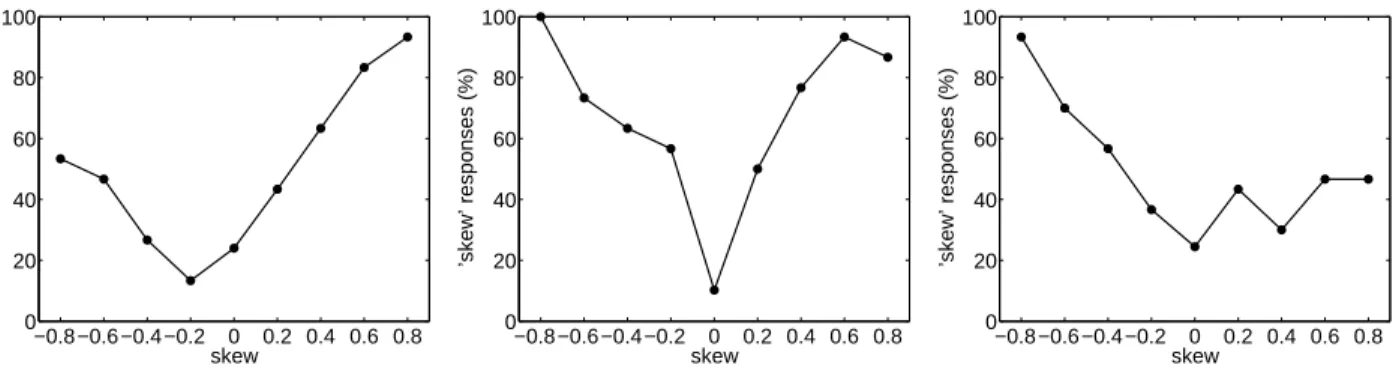
Twenty observers were each shown examples of undistorted and skewed images, and instructed that their task would be to determine if an image was skewed. In the center panel condition, there was minimal perspective distortion and we expected all observers to accurately detect skew in the image. Nonetheless, five observers performed below 70% overall and their data were eliminated from this analysis. The remaining observers showed the expected pattern of results for the center panel, reliably detecting large positive and negative skews (center panel of Figure 4). Of interest is how these observers performed when the panel was viewed obliquely and the image was subjected to perspective distortions (left and right panels). Here the pattern of results is asymmetrical depending on whether the skew in the image exaggerated or counteracted the perspective distortion. When the skew exaggerated the perspective distortion (positive image skew, left panel; negative image skew, right panel) performance was good. When the skews counteracted the perspective distortion, performance was at or below chance. That is, observers were unable to detect even a large skew when the effects of perspective distorted counteracted the skew. These results suggest that observers underestimate or possibly even ignore the effects of
Figure 3. The image on each of the planes in panel (a) are the same. The image on the left-most plane in panel (b) is a skewed version of the image on the central plane, as shown in the rectified images below.
−0.8−0.6−0.4−0.2 0 0.2 0.4 0.6 0.8 0 20 40 60 80 100 skew
’skew’ responses (%)
−0.8−0.6−0.4−0.2 0 0.2 0.4 0.6 0.8 0 20 40 60 80 100 skew
’skew’ responses (%)
−0.8−0.6−0.4−0.2 0 0.2 0.4 0.6 0.8 0 20 40 60 80 100 skew
’skew’ responses (%)
Figure 4. Skew estimation accuracy for each of three planar panels (left, center, right, respectively) shown in Figure 3.
perspective projection. Averaging over all conditions, observer accuracy for the left and right panel was 63.1% and 64.4%, compared to 82.6% on the center panel. The average response time was 2.8 seconds, indicating that observers spent a reasonable amount of time inspecting each scene.
3.2 Geometry of Planar Perspective
Observers routinely underestimate the amount of distortion caused by planar perspective distortion. From a computational point of view, the perspective transformation of a planar surface is relatively easy to model and estimate.14, 15 The mapping from points in 3-D world coordinates to 2-D image coordinates can be expressed by the projective imaging equation: ~x = P ~X, where the 3×4 matrixP embodies the projective transform, the vectorX~ is a 3-D world point in homogeneous coordinates, and the vector~x is a 2-D image point also in homogeneous coordinates. In the case when all of the world pointsX~ lie on a single plane, the transform reduces to a 3×3 planar projective transformH, also known as a homography:
~x = H ~X, (1)
where the worldX~ and image points~xare now represented by 2-D homogeneous vectors.
In order to estimate the homographyH, we begin with a cross production formulation of Equation (1): ~x×[H ~X] = 0
x1 x2 x3 ×
h1 h2 h3 h4 h5 h6 h7 h8 h9
X1 X2 X3
= 0. (2)
Evaluating the cross product yields:
x2(h7X1+h8X2+h9X3)−x3(h4X1+h5X2+h6X3) x3(h1X1+h2X2+h3X3)−x1(h7X1+h8X2+h9X3) x1(h4X1+h5X2+h6X3)−x2(h1X1+h2X2+h3X3)
= 0. (3)
This constraint is linear in the unknown elements of the homography hi. Re-ordering the terms yields the
following system of linear equations:
0 0 0 −x3X1 −x3X2 −x3X3 x2X1 x2X2 x2X3
x3X1 x3X2 x3X3 0 0 0 −x1X1 −x1X2 −x1X3
−x2X1 −x2X2 −x2X3 x1X1 x1X2 x1X3 0 0 0
h1 h2 h3 h4 h5 h6 h7 h8 h9 = 0
Figure 5. The face of each cigarette box in panel (a) is rectified using the known dimensions of the box face. Shown in panels (b) and (c) are the rectified images, revealing an inconsistency in the cartoon character and text.
A matched set of worldX~ and image~xcoordinates appears to provide three constraints on the eight unknown elements of H (the homography is defined up to an unknown scale factor, reducing the number of unknowns from nine to eight). The rows of the matrix A, however, are not linearly independent (the third row is a linear combination of the first two rows). As such, this system provides only two constraints in the eight unknowns. Therefore, a total of four or more points with known world and image coordinates are required to estimate the homography. From these points, standard least-squares techniques can be used to solve for~h: the minimal eigenvalue eigenvector of ATA is the unit vector~h that minimizes the least-squares error kA~hk2. The inverse homographyH−1 is applied to the image to remove planar perspective distortion.
Figure 5(a) is a forgery of our creation – two boxes of Marlboro cigarettes were doctored to read “Marlboro kids” with an image of the cartoon character Tweety Bird. On both boxes, the “kids” text and the character were manually adjusted to give the appearance of correct perspective. Figure 5(b) and (c) are the results of planar rectification based on the known shape of the rectangle on the front of the box (1 11/16×3 1/8 inches, determined by measuring an actual box of cigarettes). Note that after rectification the text and character on the boxes are inconsistent with one another, clearly revealing the image to be a fake.
4. REFLECTIONS
4.1 Human Performance
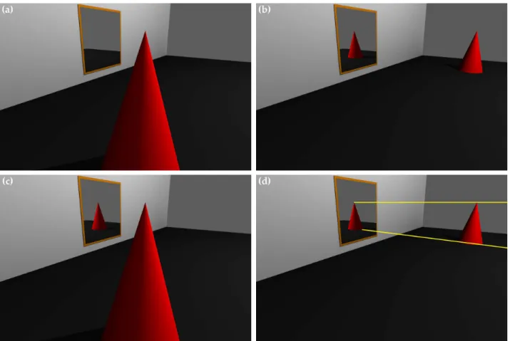
Figure 6(a) is a rendered 3-D scene containing a red cone and a mirror. Panel (b) of this figure is the same scene with the cone displaced relative to the mirror. Panel (c) is a composite created by replacing the correct reflection in panel (a) with that from panel (b) to create a physically impossible scene. Three-dimensional rendered scenes were generated such that the reflection was either consistent or inconsistent with the scene geometry, Figure 6. The scenes were rendered with the viewer in one of three locations relative to the reflective mirror, either 10◦
(nearly fronto-parallel) or ±60◦ relative to the mirror. For each viewing direction, the object (red cone) was
moved to one of three locations along the ground plane. The inconsistent scenes were generated by combining the reflection from one scene with the object from another, always taken from scenes with the same viewing direction. Twenty observers were each presented with these scenes (14 consistent and 28 inconsistent) and given unlimited time to determine if the reflection in each was correct. The average accuracy over all viewing conditions was only 55.7%, slightly better than chance. The average response time was 7.6 seconds, indicating that observers spent a reasonable amount of time inspecting each scene.
4.2 Geometry of Reflections
Observers were largely unable to predict the location of an object’s reflection in a planar mirror. This failure might not seem surprising given that the task requires knowledge of 3-D scene geometry. However, if the reflective
Figure 6. The reflections in the planar mirror in panels (a) and (b) are consistent with the scene geometry. The scene in panel (c) is a composite of the object from panel (a) and the reflection from panel (b). In this case, the reflection and scene geometry are inconsistent The yellow lines in panel (d) constrain the location of the object relative to the reflection.
surface is planar with known dimensions, there is sufficient information in the image to constrain the relationship between an object and its reflection. The law of reflection states that a light ray reflects from a surface at an angle of reflectionθrequal to the angle of incidenceθi, measured with respect to the surface normal. Assuming
unit-length vectors, the direction from the reflection to the object Z~ can be described in terms of the view direction V~ and surface normalN~ as:
~
Z = 2 cos(θi)N~ −V~ = 2(V~TN~)N~ −V .~ (5)
In order to estimate the view direction and surface normal in a common coordinate system, we must first determine the homographyH that maps the reflective planar surface from world to image coordinates. This estimation is the same as that described in Section 3. Once estimated, the homography is factored as:
H = λK(~r1 ~r2 ~t), (6)
where λ is a scale factor, the matrix K embodies the internal camera parameters, and where the rigid body transformation from world to camera coordinates is specified by a translation vector~t, and a rotation matrix
Rwhose first two columns are~r1 and~r2. The full rotation matrix is (~r1 ~r2 ~r1×~r2).If we assume that the camera has unit aspect ratio and zero skew (i.e., square pixels), and that the principle point is the image center, then the intrinsic matrix simplifies to:
K =
f 0 0 0 f 0 0 0 1
, (7)
wheref is the focal length. Substituting this intrinsic matrix into Equation (6) gives:
H = λ
f 0 0 0 f 0 0 0 1
(~r1 ~r2 ~t). (8)
Left-multiplying byK−1 yields:
1
f 0 0
0 1
f 0
0 0 1
H = λ(~r1 ~r2 ~t)
1
f 0 0
0 1
f 0
0 0 1
h1 h2 h3 h4 h5 h6 h7 h8 h9
= λ(~r1 ~r2 ~t) (9)
Because ~r1 and~r2 are the first two columns of a rotation (orthonormal) matrix, their inner product,~rT
1 ·~r2, is zero, leading to the following constraint:
1
f 0 0
0 1
f 0
0 0 1
h1 h4 h7 T · 1
f 0 0
0 1
f 0
0 0 1
h2 h5 h8
= 0
(h1 h4 h7)
1
f2 0 0
0 1
f2 0
0 0 1
h2 h5 h8
= 0. (10)
The focal length is estimated by solving the above linear system for f:
f =
r
−h1h2+h4h5
h7h8 . (11)
The additional constraint that~r1and~r2 are each unit length,~rT
1 ·~r1=~r
T
2 ·~r2, can also be used to estimate the focal length.14 The scale factor λis determined by enforcing unit norm on the columns of the rotation matrix:
λ = 1 kK−1~h1k =
1
k~r1k (12)
where~h1 is the first column of the matrixH.
With the homography factored, the desired view direction and surface normal can each be estimated in a common coordinate system. The view direction, in camera coordinates, is given by:
~
V = 1 λK
−1H(X Y 1 )T
, (13)
where (X Y) is the location of the reflection in world coordinates. These coordinates are determined by first applyingH−1to the image, in order to planar rectify the reflective surface. A point (X Y ) on the reflection is then selected. Without loss of generality, we assume that the world plane is positioned at unit length from the
Figure 7. Flamingos from Miami’s MetroZoo seek shelter from Hurricane Georges (Joe Cavaretta / Associated Press / Sept. 1998). On the right is a magnified view of the flamingos and their reflection. The yellow lines show that the position of the reflections are consistent with the scene geometry.
origin (i.e.,Z = 1). The surface normal in world coordinates is ( 0 0 −1 )T (i.e., along theZ-axis and facing the origin), and in camera coordinates:
~
N = R( 0 0 −1 )T. (14)
WithV~ andN~ estimated, the directionZ~ to the object is then determined from Equation (5).
Note that all of these directions and normals are specified in the camera coordinate system. As such, they can each be projected into image coordinates and used to determine if an object and its reflection are consistent. Specifically, in the original image, a line is drawn from a point on the reflection toK(V~ +Z~), Figure 6(d). Note, however, that this constraint does not uniquely define the location of the object, as the reflection is consistent with an object anywhere along the constraint line.
Figure 7 is a seemingly improbable, albeit authentic image. The right panel is a magnified view of the flamingos and their reflection. Because the tiles surrounding the mirror are square, they were used to estimate the aspect ratio of the mirror. This known aspect ratio of 0.65 was used to estimate the homographyH, from which the object location of a reflection was estimated. Figure 7 are two such estimates, where the yellow lines connect points in the mirror with their corresponding real-world locations. Any inconsistencies in these locations could be used as evidence of tampering.
5. DISCUSSION
The human visual system is, at times, remarkably inept at detecting simple geometric inconsistencies that might result from photo tampering. We described three experiments that show that the human visual system is unable to detect inconsistencies in shadows, reflections, and planar perspective distortions. At the same time, we have described computational methods that can be applied to detect the inconsistencies that seem to elude the human visual system. These results suggest that care should be taken when making judgments of photo authenticity based solely on visual inspection.
ACKNOWLEDGMENTS
Thanks to Christopher Kapsales for his help with the data collection. This work was supported by a gift from Adobe Systems, Inc., a gift from Microsoft, Inc., and a grant from the National Science Foundation (CNS-0708209).
REFERENCES
[1] Westheimer, G. and McKee, S., “Visual acuity in the presence of retinal-image motion,” Journal of the Optical Society of America65, 847–850 (1975).
[2] Potter, M., “Short-term conceptual memory for pictures,” Journal of Experimental Psychology: Human Learning and Memory2, 509–522 (1976).
[3] Sinha, P., Balas, B., Ostrovsky, Y., and Russell, R., “Face recognition by humans: 19 results all computer vision researchers should know about,”Proceedings of the IEEE94(11), 1948–1962 (2006).
[4] Ostrovsky, Y., Cavanagh, P., and Sinha, P., “Perceiving illumination inconsistencies in scenes,” Percep-tion 34, 1301–1314 (2005).
[5] Vishwanath, D., Girshick, A., and Banks, M., “Why pictures look right when viewed from the wrong place,” Nature Neuroscience10(8), 1401–1410 (2005).
[6] Adelson, E. H., [The New Cognitive Neurosciences, 2nd Edition], ch. Lightness Perception and Lightness Illusions, 339–351, MIT Press (2000).
[7] Jacobson, J. and Werner, S., “Why cast shadows are expendable: Insensitivity of human observers and the inherent ambiguity of cast shadows in pictorial art,”Perception33(11), 1369–1383 (2004).
[8] Bertamini, M., Spooner, A., and Hecht, H., “Predicting and perceiving reflections in mirrors,” Journal of Experimental Psychology: Human Perception and Performance39, 982–1002 (2003).
[9] Bravo, M. and Farid, H., “Texture perception on folded surfaces,”Perception30(7), 819–832 (2001). [10] Ritschel, T., Okabe, M., Thorm¨ahlen, T., and Seidel, H.-P., “Interactive reflection editing,” ACM Trans.
Graph. (Proc. SIGGRAPH Asia 2009) 28(5) (2009).
[11] Zhang, W., Cao, X., Zhang, J., Zhu, J., and Wang, P., “Detecting photographic composites using shadows,” in [IEEE International Conference on Multimedia and Expo], 1042–1045 (2009).
[12] Johnson, M. and Farid, H., “Exposing digital forgeries by detecting inconsistencies in lighting,” in [ACM Multimedia and Security Workshop], (2005).
[13] Johnson, M. and Farid, H., “Exposing digital forgeries in complex lighting environments,” IEEE Transac-tions on Information Forensics and Security3(2), 450–461 (2007).
[14] Hartley, R. and Zisserman, A., [Multiple View Geometry in Computer Vision], Cambridge University Press (2004).
[15] Johnson, M. and Farid, H., “Metric measurements on a plane from a single image,” Tech. Rep. TR2006-579, Department of Computer Science, Dartmouth College (2006).