Layer 3+ Chassis Switch
AT-SBx81CFC960
Controller Fabric Card
AT-SBx8112 Chassis
AT-SBx81GT24 Ethernet Line Card
AT-SBx81GT40 Ethernet Line Card
AT-SBx81GP24 Ethernet PoE Line Card
AT-SBx81GS24a Ethernet SFP Line Card
AT-SBx81XS6 Ethernet SFP+ Line Card
AT-SBx81XS16 Ethernet SFP+ Line Card
AT-SBxPWRSYS1 AC and DC Power
Supplies
AT-SBxPWRPOE1 PoE Power Supply
Allied Telesis, AlliedWare Plus, VCStack Plus, and the Allied Telesis logo are trademarks of Allied Telesis, Incorporated. All other product names, company names, logos or other designations mentioned herein are trademarks or registered trademarks of their respective owners.
Allied Telesis, Inc. reserves the right to make changes in specifications and other information contained in this document without prior written notice. The information provided herein is subject to change without notice. In no event shall Allied Telesis, Inc. be liable for any incidental, special, indirect, or consequential damages whatsoever, including but not limited to lost profits, arising out of or related to this manual or the information contained herein, even if Allied Telesis, Inc. has
This product meets the following standards
EMI/RFI Emissions: FCC Class A, EN55022 Class A, EN61000-3-2, EN61000-3-3, CISPR Class A, VCCI Class A, AS/NZS Class A
Immunity: EN55024
Electrical Safety: EN60950-1 (TUV), UL 60950-1 (CULUS), EN60825 Safety Agency Approvals: CULUS, TUV, C-TICK, CE
U.S. Federal Communications Commission
Radiated Energy
Note: This equipment has been tested and found to comply with the limits for a Class A digital device pursuant to Part 15 of FCC Rules. These limits are designed to provide reasonable protection against harmful interference when the equipment is operated in a commercial environment. This equipment generates, uses, and can radiate radio frequency energy and, if not installed and used in accordance with this instruction manual, may cause harmful interference to radio communications. Operation of this equipment in a residential area is likely to cause harmful interference in which case the user will be required to correct the interference at his own expense.
Note: Modifications or changes not expressly approved of by the manufacturer or the FCC, can void your right to operate this equipment.
Industry Canada
This Class A digital apparatus complies with Canadian ICES-003.
Cet appareil numérique de la classe A est conforme à la norme NMB-003 du Canada.
European Union Restriction of the Use of Certain Hazardous Substances (RoHS) in Electrical and Electronic Equipment
This Allied Telesis RoHS-compliant product conforms to the European Union Restriction of the Use of Certain Hazardous Substances (RoHS) in Electrical and Electronic Equipment. Allied Telesis ensures RoHS conformance by requiring supplier Declarations of Conformity, monitoring incoming materials, and maintaining manufacturing process controls.
Warning: In a domestic environment this product may cause radio interference in which case the user may be required to take adequate measures.
Translated Safety Statements
Important: The indicates that a translation of the safety statement is available in a PDF document titled “Translated Safety Statements” on our web site at
Preface ...15
Structure of the Installation Guide ...16
Safety Symbols Used in this Document ...17
Contacting Allied Telesis ...18
Section I: Hardware Overview ... 19
Chapter 1: Chassis and Power Supplies ...21
Introduction...22
AT-SBx8112 Chassis ...24
Slots for the Ethernet Line and Controller Cards...26
Slots for the Power Supplies ...27
AT-SBxPWRSYS1 Power Supply ...28
LEDs ...28
AT-SBxPWRPOE1 Power Supply ...30
LEDs ...30
AT-SBxPWRSYS1 DC Power Supply ...32
LEDs ...33
AT-SBxFAN12 Module ...34
LED ...34
Power Supply Interfaces (Opto-couplers)...35
LED ...35
Chapter 2: Ethernet Line Cards ...37
Ethernet Line Cards...38
AT-SBx81GT24 Line Card...39
LEDs ...39
AT-SBx81GT40 Line Card...41
LEDs ...42
AT-SBx81GP24 PoE Line Card...44
LEDs ...45
AT-SBx81GS24a SFP Line Card ...47
LEDs ...47
AT-SBx81XS6 SFP+ Line Card...49
LEDs ...49
AT-SBx81XS16 SFP+ Line Card...51
LEDs ...51
10/100/1000Base-T Twisted Pair Ports...53
Connector Type...53
Speed...53
Duplex Mode ...53
Maximum Distance...53
Cable Requirements ...54
Automatic MDIX Detection ...55
Powered Device Classes... 56
Power Budget ... 57
PoE Wiring... 57
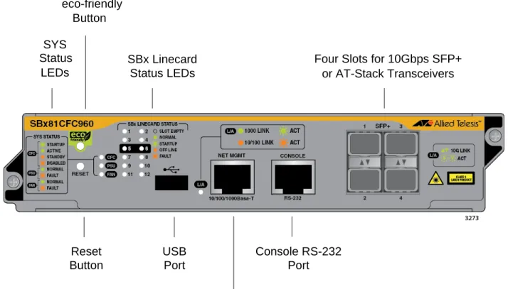
Chapter 3: AT-SBx81CFC960 Controller Fabric Card ... 59
Hardware Components ... 60
Guidelines ... 62
Dual Controller Cards ... 64
SYS Status LEDs ... 66
eco-friendly Button ... 68
SBx Linecard Status LEDs... 69
SFP+ Slots ... 70
Console (RS-232) Port... 72
Ethernet Management Port (NET MGMT) ... 73
NET MGMT LED ... 73
USB Port ... 75
Reset Button ... 76
AlliedWare Plus Software Releases for the Hardware Components ... 78
Section II: Installing the Chassis ... 79
Chapter 4: Safety Precautions and Site Requirements ... 81
Reviewing Safety Precautions ... 82
Selecting a Site for the SwitchBlade x8112 ... 86
Installation Tools and Material ... 88
Chapter 5: Installing the Chassis in an Equipment Rack ... 89
Required Tools and Material ... 90
Preparing the Equipment Rack ... 91
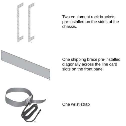
Unpacking the AT-SBx8112 Chassis ... 94
Adjusting the Equipment Rack Brackets ... 96
Installing the AT-SBx8112 Chassis in the Equipment Rack... 98
Removing the Shipping Brace ... 101
Installing the Chassis Grounding Wire ... 102
Chapter 6: Installing the Power Supplies ... 105
Protecting Against Electrostatic Discharge (ESD) ... 106
Installing the AT-SBxPWRSYS1 AC System Power Supply... 107
Installing the AT-SBxPWRPOE1 PoE Power Supply... 113
Installing the AT-SBxPWRSYS1 DC System Power Supply... 119
Chapter 7: Installing the AT-SBx81CFC960 Control Card and Ethernet Line Cards ... 125
Guidelines to Handling the Controller and Line Cards ... 126
Installing the AT-SBx81CFC960 Controller Fabric Card... 128
Installing the Ethernet Line Cards ... 134
Installing the Blank Slot Covers ... 139
Chapter 8: Installing the Transceivers and Cabling the Ports ... 141
Cabling Guidelines for the Twisted Pair Ports on the AT-SBx81GT24, AT-SBx81GT40, and AT-SBx81GP24 Line Cards ... 142
Connecting Cables to the AT-SBx81GT40 Line Card ... 143
Guidelines to Installing SFP and SFP+ Transceivers ... 145
Installing SFP Transceivers in the AT-SBx81GS24a Line Card ... 146
Installing SFP+ Transceivers in the AT-SBx81XS6 Line Card... 150
Installing AT-SP10TW Cables in the AT-SBx81XS16 Line Card ...160
Cabling the NET MGMT Port on the AT-SBx81CFC960 Card ...162
Installing SFP+ Transceivers in the AT-SBx81CFC960 Card ...164
Chapter 9: Powering On the Chassis ...169
Verifying the Installation ...170
Powering On the AT-SBxPWRSYS1 AC System Power Supply...171
Powering On the AT-SBxPWRPOE1 Power Supply ...174
Powering On the AT-SBxPWRSYS1 DC System Power Supply ...177
Choosing a Method for Attaching the Grounding Wire...179
Connecting the Grounding Wire with the Grounding Terminal...179
Connecting the Grounding Wire with Bare Wire ...182
Choosing a Method for Attaching the Power Wires ...184
Connecting the DC Power Wires with the Straight Terminals...184
Connecting the DC Power Wires with the Right Angle Terminals...193
Connecting Bare DC Power Wires...199
Monitoring the Initialization Process ...203
Using the LEDs to Monitor the Initialization Process ...203
Using the Console Port to Monitor the Initialization Process ...203
Chapter 10: Verifying the Hardware Operations of the Chassis ...207
Using the LEDs to Verify the Chassis...208
Using Local Management to Verify the Chassis...210
Starting a Local Management Session ...210
Entering the AlliedWare Plus Operating System Commands ...211
Chapter 11: Troubleshooting ...213
AT-SBxPWRSYS1 and AT-SBxPWRPOE1 AC Power Supplies ...214
AT-SBxPWRSYS1 DC System Power Supply ...215
Ethernet Line Cards...217
Twisted Pair Ports ...219
Power Over Ethernet ...221
Fiber Optic or Twisted Pair Transceivers ...223
AT-SBx81CFC960 Controller Fabric Card ...224
AT-SBxFAN12 Fan Module ...225
Local (Console) Management Session...226
Power Supply Interfaces (Opto-couplers)...227
Chapter 12: Replacing Modules ...229
Replacing the AT-SBxPWRSYS1 AC or AT-SBxPWRPOE1 Power Supply ...230
Replacing the AT-SBxPWRSYS1 DC Power Supply ...235
Replacing Ethernet Line Cards...246
Replacing the AT-SBx81CFC960 Controller Fabric Card ...248
Replacing the AT-SBxFAN12 Fan Module ...251
Removing the AT-SBxFAN12 Fan Module ...251
Installing a New AT-SBxFAN12 Fan Module ...255
Chapter 13: Upgrading the Controller Fabric Card ...259
Before You Begin ...260
Upgrading the Controller Fabric Card...262
Section III: Building a Stack with VCStack Plus ... 267
Chapter 14: VCStack Plus Overview ...269
Overview...270
Stack Trunk and Stacking Transceivers ...271
Two Controller Cards Per Chassis ... 274
VCStack Plus Feature License ... 276
Optional Feature Licenses ... 277
Chassis ID Numbers ... 278
Priority Numbers ... 279
Stacking Guidelines ... 281
Chapter 15: Building a Stack ... 283
Before You Begin ... 284
Displaying the Management Software Version Number ... 285
Activating the VCStack Plus Feature License... 287
Enabling the Stacking Feature ... 289
Displaying the Feature Licenses ... 291
Setting the ID Number ... 293
Setting the Priority Number ... 297
Powering Off the Chassis ... 298
Configuring the Second Chassis... 299
Installing and Cabling the Stacking Transceivers ... 300
Powering On the Stack ... 303
Controlling the Selection of the Initial Active Master Controller Card ... 303
Powering On the Switches ... 304
Monitoring the Boot Up Sequence... 304
Verifying the Stack ... 307
Installing Optional Feature Licenses ... 309
Troubleshooting the Stack ... 310
Appendix A: Technical Specifications ... 313
Physical Specifications ... 313
Environmental Specifications ... 315
Power Specifications... 316
Safety and Electromagnetic Emissions Certifications ... 318
Port Pinouts ... 319
Figure 1: AT-SBx8112 Chassis ... 22
Figure 2: Power Supply Units ... 23
Figure 3: Fan Module ... 23
Figure 4: Front View of the AT-SBx8112 Chassis ... 24
Figure 5: Rear View of the AT-SBx8112 Chassis... 25
Figure 6: AT-SBx8112 Chassis with Line Cards, Controller Cards, and Power Supplies ... 25
Figure 7: Ethernet Line and Controller Cards Slots ... 26
Figure 8: Power Supply Slots ... 27
Figure 9: AT-SBxPWRSYS1 Power Supply ... 28
Figure 10: AT-SBxPWRPOE1 Power Supply ... 30
Figure 11: AT-SBxPWRSYS1 DC Power Supply ... 32
Figure 12: AT-SBxFAN12 Module ... 34
Figure 13: Power Supply Interfaces (Opto-couplers)... 35
Figure 14: Ethernet Line Cards ... 38
Figure 15: AT-SBx81GT24 Line Card... 39
Figure 16: Port LEDs on the AT-SBx81GT24 Line Card ... 40
Figure 17: AT-SBx81GT40 Line Card... 41
Figure 18: Port LEDs on an RJ Point 5 Cable Connector for the AT-SBx81GT40 Line Card ... 42
Figure 19: Port LEDs on an RJ Point 5 Cable Connector for the AT-SBx81GT40 Line Card ... 42
Figure 20: AT-SBx81GP24 PoE Line Card... 44
Figure 21: Port LEDs on the AT-SBx81GP24 PoE Line Card ... 45
Figure 22: AT-SBx81GS24a SFP Line Card ... 47
Figure 23: Port LEDs on the AT-SBx81GS24a SFP Line Card ... 48
Figure 24: AT-SBx81XS6 Line Card... 49
Figure 25: SFP+ Slot LEDs on the AT-SBx81XS6 Line Card... 49
Figure 26: AT-SBx81XS16 Line Card... 51
Figure 27: SFP+ Slot LEDs on the AT-SBx81XS16 Line Card... 52
Figure 28: AT-SBx81CFC960 Controller Fabric Card ... 60
Figure 29: 100 - 125 VAC 125 V NEMA 5-20 Plug and Receptacle... 87
Figure 30: Reserving Vertical Rack Space ... 92
Figure 31: Rack Mounting Hole Locations... 93
Figure 32: Components of the AT-SBx8112 Chassis ... 94
Figure 33: Components of the AT-SBx8112 Chassis (Continued) ... 95
Figure 34: Rack Mounting Bracket Locations ... 97
Figure 35: Rack Bracket Locations for Reverse Position of Chassis... 97
Figure 36: Lifting the AT-SBx8112 Chassis into the Equipment Rack... 99
Figure 37: Installing the Rack Mount Screws ... 100
Figure 38: Removing the Shipping Brace ... 101
Figure 39: Stripping the Grounding Wire ... 102
Figure 40: Removing the Grounding Lug... 102
Figure 41: Attaching the Grounding Wire to the Grounding Lug... 103
Figure 42: Installing the Grounding Lug and Wire ... 103
Figure 43: ESD Socket and Wrist Strap ... 106
Figure 44: Power Supply Slots ... 107
Figure 45: Removing the Blank Slot Cover from Power Supply Slot C ... 108
Figure 46: Items Included with the AT-SBxPWRSYS1 Power Supply Module... 109
Figure 47: Verifying the AT-SBxPWRSYS1 Power Supply ... 110
Figure 48: Unlocking the Handle on the AT-SBxPWRSYS1 Power Supply ... 110
Figure 51: Removing the Blank Slot Cover from Power Supply Slot A... 114
Figure 52: Items Included with the AT-SBxPWRPOE1 Power Supply Module... 115
Figure 53: Verifying the AT-SBxPWRPOE1 PoE Power Supply ... 116
Figure 54: Unlocking the Handle on the AT-SBxPWRPOE1 Power Supply ... 116
Figure 55: Inserting the AT-SBxPWRPOE1 Power Supply ... 117
Figure 56: Locking the Handle on the AT-SBxPWRPOE1 Power Supply ... 118
Figure 57: Removing the Blank Slot Cover from Power Supply Slot C... 120
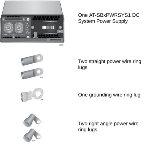
Figure 58: Items Included with the AT-SBxPWRSYS1 DC Power Supply Module... 121
Figure 59: On/Off Switch on the AT-SBxPWRSYS1 DC Power Supply ... 122
Figure 60: Loosening the Handle locking Screw on the AT-SBxPWRSYS1 DC System Power Supply ... 122
Figure 61: Raising Handle on the AT-SBxPWRSYS1 DC Power Supply ... 123
Figure 62: Inserting the AT-SBxPWRSYS1 DC System Power Supply... 123
Figure 63: Locking the Handle on the AT-SBxPWRSYS1 DC System Power Supply... 124
Figure 64: Aligning a Card in a Slot ... 127
Figure 65: Slots 5 and 6 for the AT-SBx81CFC960 Card ... 128
Figure 66: Items Included with the AT-SBx81CFC960 Controller Card... 129
Figure 67: Removing the AT-SBx81CFC960 Controller Fabric Card from the Anti-static Bag ... 129
Figure 68: Removing the Battery Insulator ... 130
Figure 69: Opening the Locking Handles on the AT-SBx81CFC960 Controller Fabric Card ... 130
Figure 70: Aligning the AT-SBx81CFC960 Card in the Chassis Slot... 131
Figure 71: Closing the Locking Levers on the AT-SBx81CFC960 Controller Fabric Card ... 132
Figure 72: Tightening the Thumb Screws on the AT-SBx81CFC960 Card ... 133
Figure 73: Slots 1 to 4 and 7 to 12 for the Ethernet Line Cards... 134
Figure 74: Removing an Ethernet Line Card from the Anti-static Bag ... 135
Figure 75: Aligning an Ethernet Line Card in a Chassis Slot ... 136
Figure 76: Seating an Ethernet Line Card on the Backplane Connector ... 137
Figure 77: Tightening the Thumb Screws on an Ethernet Line Card... 137
Figure 78: Installing a Blank Slot Cover... 139
Figure 79: Tightening the Thumbscrews on a Blank Slot Cover... 139
Figure 80: RJ Point 5 Cable Connector for AT-SBx81GT40 Line Card ... 143
Figure 81: Connecting Cables to Ports on the AT-SBx81GT40 Line Card ... 144
Figure 82: Removing the Dust Cover from an SFP Slot in the AT-SBx81GS24a Line Card ... 146
Figure 83: Handle on SFP Transceiver... 147
Figure 84: Inserting the SFP Transceiver in the AT-SBx81GS24a Line Card ... 147
Figure 85: Removing the Dust Cover from the SFP Transceiver in the AT-SBx81GS24a Line Card... 148
Figure 86: Verifying the Position of the Handle on an SFP Transceiver in the AT-SBx81GS24a Line Card... 148
Figure 87: Attaching a Fiber Optic Cable to an SFP Transceiver in the AT-SBx81GS24a Line Card ... 149
Figure 88: Removing the Dust Cover from an SFP+ Slot in the AT-SBx81XS6 Line Card ... 150
Figure 89: Handle on SFP+ Transceiver ... 151
Figure 90: Installing an SFP+ Transceiver in the AT-SBx81XS6 Line Card ... 151
Figure 91: Removing the Dust Cover from an SFP+ Transceiver in the AT-SBx81XS6 Line Card ... 152
Figure 92: Verifying the Position of the Handle on the SFP+ Transceiver in the AT-SBx81XS6 Line Card ... 152
Figure 93: Attaching a Fiber Optic Cable to an SFP+ Transceiver in the AT-SBx81XS6 Line Card ... 153
Figure 94: Removing the Dust Cover From an SFP+ Slot in the AT-SBx81XS6 Line Card ... 154
Figure 95: Installing the AT-SP10TW Cable in the AT-SBx81XS6 Line Card ... 155
Figure 96: Removing the Dust Cover from a Transceiver Slot in the AT-SBx81XS16 Line Card... 156
Figure 97: Installing a Transceiver in the AT-SBx81XS16 Line Card ... 157
Figure 98: Removing the Dust Cover from a Transceiver in the AT-SBx81XS16 Line Card ... 157
Figure 99: Verifying the Position of the Handle on the Transceiver in the AT-SBx81XS16 Line Card ... 158
Figure 100: Attaching a Fiber Optic Cable to a Transceiver in the AT-SBx81XS16 Line Card ... 159
Figure 101: Removing the Dust Cover From an SFP+ Slot on the AT-SBx81XS16 Line Card ... 160
Figure 102: Installing the AT-SP10TW Cable in the AT-SBx81XS16 Line Card ... 161
Figure 103: Removing a Dust Cover from an SFP+ Slot in the AT-SBx81CFC960 Controller Fabric Card ... 164
Figure 104: Handle on an SFP+ Transceiver ... 165
Figure 105: Installing an SFP+ Transceiver in the AT-SBx81CFC960 Controller Fabric Card... 165
Figure 106: Removing the Dust Cover from an SFP+ Transceiver in the AT-SBx81CFC960 Controller Fabric Card ... 166
Figure 107: Positioning the Handle on the Transceiver ... 167
Figure 110: Connecting the AC Power Cord for the AT-SBxPWRSYS1 AC Power Supply ... 172
Figure 111: Securing the Power Cord for the AT-SBxPWRSYS1 AC Power Supply to an Anchor... 173
Figure 112: Connecting the AC Power Cord for the AT-SBxPWRPOE1 Power Supply... 174
Figure 113: Securing the Power Cord for the AT-SBxPWRPOE1 Power Supply to an Anchor ... 175
Figure 114: Dress and Secure AC Power Cords ... 176
Figure 115: Components of the AT-SBxPWRSYS1 DC Power Supply... 178
Figure 116: Grounding Wire Terminal ... 179
Figure 117: Stripping the Stranded Grounding Wire... 179
Figure 118: Attaching the Stranded Grounding Wire to the Grounding Terminal ... 179
Figure 119: Removing the Nut and Washer from the Grounding Post ... 180
Figure 120: Installing the Grounding Wire ... 181
Figure 121: Stripping the solid or Stranded Grounding Wire ... 182
Figure 122: Attaching the Bare Grounding Wire to the Grounding Post... 182
Figure 123: Securing the Bare Grounding Wire to the Grounding Post... 183
Figure 124: Power Wire Terminals ... 184
Figure 125: Stripping the Power Wires ... 185
Figure 126: Attaching the Power Wires to the Straight Terminal Lugs ... 185
Figure 127: On/Off Switch on the AT-SBxPWRSYS1 DC Power Supply ... 186
Figure 128: Opening the Plastic Cover... 187
Figure 129: Removing the Terminal Screws... 188
Figure 130: Connecting the Positive (+) Power Wire with a Straight Terminal... 189
Figure 131: Connecting the Negative (-) Power Wire with a Straight Terminal ... 190
Figure 132: Closing the Plastic Cover over the Terminal Connectors ... 191
Figure 133: Tightening the Handle Locking Screw ... 192
Figure 134: Stripping the Power Wires ... 193
Figure 135: Attaching the Power Wires to the Right Angle Terminals... 193
Figure 136: Removing the Plastic Cover ... 194
Figure 137: Removing the Terminal Screws... 195
Figure 138: Connecting the Positive (+) Power Wire with a Right Angle Terminal... 196
Figure 139: Connecting the Negative (-) Power Wire with a Right Angle Terminal ... 197
Figure 140: Tightening the Handle Locking Screw ... 198
Figure 141: Stripping Solid or Stranded DC Power Wires ... 199
Figure 142: Connecting the Positive Wire With Bare Wire ... 200
Figure 143: Connecting the Negative Lead Wire with Bare Wire ... 201
Figure 144: Initialization Messages for a Stand-alone Switch ... 204
Figure 145: Initialization Messages for a Stand-alone Switch (Continued) ... 205
Figure 146: Connecting the Management Cable to the Console RS-232 Port ... 210
Figure 147: SHOW VERSION Command... 211
Figure 148: SHOW CARD Command... 212
Figure 149: Disconnecting the AC Power Cord from the AC Socket on the Back Panel... 230
Figure 150: Lifting the Locking Handle on the Power Supply ... 231
Figure 151: Removing the Power Supply from the Chassis ... 232
Figure 152: Installing a Blank Power Supply Slot Cover ... 233
Figure 153: Lowering the Locking Handle on the Power Supply Slot Cover ... 234
Figure 154: Loosening the Screw on the Locking Handle ... 235
Figure 155: Opening the Plastic Window over the Terminal Block... 236
Figure 156: Removing the Negative Lead Wire... 237
Figure 157: Removing the Positive Lead Wire from the Terminal Block ... 238
Figure 158: Reinstalling the Screws on the Positive and Negative Terminals... 239
Figure 159: Closing the Plastic Cover ... 240
Figure 160: Removing the Grounding Wire ... 241
Figure 161: Reinstalling the Nut and Washer on the Grounding Post ... 242
Figure 162: Lifting the Locking Handle and Removing the Power Supply... 243
Figure 163: Installing a Blank Power Supply Slot Cover ... 244
Figure 164: Lowering the Locking Handle on the Power Supply Slot Cover ... 245
Figure 165: Loosening the Screw on the AT-SBxFAN12 Fan Module ... 252
Figure 166: Loosening the AT-SBxFAN12 Fan Module from the Backplane Connector... 253
Figure 167: Withdrawing the AT-SBxFAN12 Fan Module 51 mm (2 In.) from the Chassis... 254
Figure 168: Removing the AT-SBxFAN12 Fan Module from the Chassis... 255
Figure 171: Tightening the Screw on the AT-SBxFAN12 Fan Module ... 258
Figure 172: Cabling the Stacking Transceivers When Both Switches have One Controller Card ... 273
Figure 173: Cabling the Stacking Transceivers When Both Switches have Two Controller Cards ... 274
Figure 174: Chassis ID Number in the Numbering Format... 278
Figure 175: SHOW SYSTEM Command ... 285
Figure 176: LICENSE Command... 288
Figure 177: LICENSE Command Message with Two Controller Cards... 288
Figure 178: LICENSE Command Message with One Controller Card... 288
Figure 179: STACK ENABLE Command Messages... 289
Figure 180: SHOW LICENSE BRIEF Command ... 291
Figure 181: SHOW STACK Command ... 293
Figure 182: STACK RENUMBER Command Messages ... 294
Figure 183: SHOW STACK Command ... 296
Figure 184: Removing the Dust Cover from an SFP+ Slot on the AT-SBx81CFC960 Controller Fabric Card ... 300
Figure 185: Handle on the AT-StackOP/0.3 and AT-StackOP/9.0 Transceivers... 300
Figure 186: Installing the AT-StackOP/0.3 or AT-StackOP/9.0 Transceiver... 301
Figure 187: Removing the Dust Cover from a Stacking Transceiver... 301
Figure 188: Positioning the Handle on the Transceiver ... 302
Figure 189: Connecting a Fiber Optic Cable to a Stacking Transceiver ... 302
Figure 190: Initialization Messages for the Stack ... 305
Figure 191: Initialization Messages for the Stack (Continued)... 306
Figure 192: SHOW STACK Command ... 307
Table 1. AT-SBxPWRSYS1 Power Supply LEDs ... 28
Table 2. AT-SBxPWRPOE1 Power Supply LEDs ... 31
Table 3. LEDs on the AT-SBxPWRSYS1 DC Power Supply ... 33
Table 4. AT-SBxFAN12 Module LED ... 34
Table 5. Power Supply Interface LED ... 36
Table 6. Port LEDs on the AT-SBx81GT24 Line Card ... 40
Table 7. Port LEDs on the AT-SBx81GT40 Line Card ... 43
Table 8. Port LEDs on the AT-SBx81GP24 PoE Line Card ... 45
Table 9. Port LEDs on the AT-SBx81GS24a SFP Line Card ... 48
Table 10. SFP+ Slot LEDs on the AT-SBx81XS6 Line Card ... 50
Table 11. SFP+ Slot LEDs on the AT-SBx81XS16 Line Card ...52
Table 12. Twisted Pair Cable for the AT-SBx81GT24 and AT-SBx81GT40 Line Cards ... 54
Table 13. Twisted Pair Cable for the AT-SBx81GP24 Line Card ... 54
Table 14. IEEE802.3af and IEEE802.3at Powered Device Classes ... 56
Table 15. Maximum Number of Powered Devices ... 57
Table 16. Components on the AT-SBx81CFC960 Controller Fabric Card ... 60
Table 17. SYS (System) Status LEDs ... 66
Table 18. SBx Linecard Status LEDs ... 69
Table 19. LEDs for the SFP+ Slots on the AT-SBx81CFC960 Controller Card ... 71
Table 20. NET MGMT Port LED ... 74
Table 21. AlliedWare Plus Operating System Releases for the Hardware Components ... 78
Table 22. Front Panel to Rack Rail Dimensions ... 96
Table 23. Stacking Transceivers ...271
Table 24. Descriptions of the STACK ENABLE Command Messages ...289
Table 25. Descriptions of the STACK RENUMBER Command Messages ...295
Table 26. Product Dimensions ...313
Table 27. Product Weights ...313
Table 28. Environmental Specifications ...315
Table 29. Acoustic Noise Test Components ...315
Table 30. AC Voltage and Frequency Requirements ...316
Table 31. DC Voltage Requirements ...316
Table 32. Typical Power Savings in eco-friendly Mode ...316
Table 33. Maximum Power Consumption ...316
Table 34. Maximum Power Efficiency ...317
Table 35. Heat Dissipation ...317
Table 36. Available Power Over Ethernet with One PoE Power Supply ...317
Table 37. Available Power Over Ethernet with Two PoE Power Supplies ...318
Table 38. PoE Mode on the AT-SBx81GP24 PoE Line Card ...318
Table 39. Safety and Electromagnetic Emissions ...318
Table 40. MDI Pin Signals (10Base-T or 100Base-TX) ...319
Table 41. MDI-X Pin Signals (10Base-T or 100Base-TX) ...319
Table 42. 1000Base-T Connector Pinouts ...320
Table 43. Fiber Optic Port Specifications for the AT-StackOP/0.3 Module ...321
This guide contains the hardware installation instructions for the Layer 3+ SwitchBlade x8112 Chassis Switch. The preface contains the following sections:
“Structure of the Installation Guide” on page 16
“Safety Symbols Used in this Document” on page 17
“Contacting Allied Telesis” on page 18
Note
This version of the installation guide applies to release 5.4.4 of the AlliedWare Plus
™
Operating System for the SwitchBlade x8112 Chassis Switch and AT-SBx81CFC960 Controller Fabric Card.Structure of the Installation Guide
This guide has the following three sections:
Section I: Hardware Overview
The chapters in this section describe the hardware components of the product, including the Ethernet line cards, AT-SBx81CFC960
Controller Fabric Card, and power supplies. You should start here if you are unfamiliar with the switch. A basic understanding of the hardware may help you avoid making mistakes during the installation procedures.
Section II: Installing the Chassis
The chapters in this section contain the hardware installation
instructions for the device. They explain how to select a site, assemble the hardware components, cable the ports, power on the unit, and confirm the hardware operations of the various components. After completing the instructions in this section, you may either begin to configure the operating parameters and features of the chassis with the commands in the command line interface of the AlliedWare Plus
™
operating systems, as described in the Software Reference for SwitchBlade x8100 Series Switches, or proceed to Section III to build a stack of two chassis with the VCStack Plus
™
feature. Section III: Building a Stack with the VCStack Plus Feature
The chapters in this section describe the VCStack Plus feature and the additional hardware and software components required to build a stack. The section also contains step-by-step instructions on how to configure the AlliedWare Plus operating systems on the switches for the stacking feature. You should perform these instructions after you have installed the two chassis of the stack at their respective sites and confirmed their operations with the instructions in the chapters in Section II of this guide. You might want to review the information in Chapter 14, “VCStack Plus Overview” on page 269 prior to installing the chassis to acquaint yourself with the feature and guidelines.
Safety Symbols Used in this Document
This document uses the following conventions.
Note
Notes provide additional information.
Caution
Cautions inform you that performing or omitting a specific action may result in equipment damage or loss of data.
Warning
Warnings inform you that performing or omitting a specific action may result in bodily injury.
Warning
Laser warnings inform you that an eye or skin hazard exists due to the presence of a Class 1 laser device.
Contacting Allied Telesis
If you need assistance with this product, you may contact Allied Telesis technical support by going to the Support & Services section of the Allied Telesis web site at www.alliedtelesis.com/support. You can find links for the following services on this page:
24/7 Online Support — Enter our interactive support center to search for answers to your product questions in our knowledge database, to check support tickets, to learn about RMAs, and to contact Allied Telesis technical experts.
USA and EMEA phone support — Select the phone number that best fits your location and customer type.
Hardware warranty information — Learn about Allied Telesis warranties and register your product online.
Replacement Services — Submit a Return Merchandise Authorization (RMA) request via our interactive support center.
Documentation — View the most recent installation and user guides, software release notes, white papers, and data sheets for your products.
Software Downloads — Download the latest software releases for your managed products.
For sales or corporate information, go to www.alliedtelesis.com/ purchase and select your region.
Hardware Overview
This section contains the following chapters:
Chapter 1, “Chassis and Power Supplies” on page 21
Chapter 2, “Ethernet Line Cards” on page 37
Chassis and Power Supplies
This chapter describes the Layer 3+ SwitchBlade x8112 Chassis Switch in the following sections:
“Introduction” on page 22
“AT-SBx8112 Chassis” on page 24
“Slots for the Ethernet Line and Controller Cards” on page 26
“Slots for the Power Supplies” on page 27
“AT-SBxPWRSYS1 Power Supply” on page 28
“AT-SBxPWRPOE1 Power Supply” on page 30
“AT-SBxPWRSYS1 DC Power Supply” on page 32
“AT-SBxFAN12 Module” on page 34
“Power Supply Interfaces (Opto-couplers)” on page 35
Note
This version of the installation guide applies to release 5.4.4 of the AlliedWare Plus
™
Operating System for the SwitchBlade x8112 Chassis Switch and AT-SBx81CFC960 Controller Fabric Card.Introduction
The SwitchBlade x8112 product is a modular Layer 3+ Ethernet switch. The main components are the AT-SBx8112 Chassis, Ethernet line cards, a controller card, system power supply, Power over Ethernet Plus (PoE+) power supply, and fan module. The AT-SBx8112 Chassis is shown in Figure 1.
Figure 1. AT-SBx8112 Chassis Figure 2 on page 23 illustrates the power supply modules.
The chassis has slots for ten Ethernet line cards, two controller cards, two system power supplies, and two PoE+ power supplies.
Figure 2. Power Supply Units Figure 3 illustrates the fan module.
Figure 3. Fan Module
AT-SBxPWRSYS1 AC Power Supply for the Ethernet line cards, controller card, and fan module.
AT-SBxPWRPOE1 AC Power Supply with 1200 W PoE budget for the ports on the AT-SBx81GP24 PoE Ethernet Line Card.
AT-SBxPWRSYS1 DC Power Supply for the Ethernet line cards, controller card, and fan module.
AT-SBxFAN12 Module Cooling module for the chassis.
AT-SBx8112 Chassis
The AT-SBx8112 Chassis is a 7RU unit with slots for ten Ethernet line cards, two controller cards, two system power supply modules, and two PoE power supply modules. The chassis components are identified in Figure 4 here and Figure 5 on page 25.
Figure 4. Front View of the AT-SBx8112 Chassis
Note
Do not remove the shipping brace from the front of the chassis until after the unit is installed in the equipment rack. You might bend the chassis and cause misalignment of the slots and card guides if you lift the chassis into the equipment rack without the shipping brace. Shipping Brace
Slots for Ethernet Line Cards and Controller Cards
PoE Power Supply Slots
Slots for Ethernet Line Cards and Controller Cards System Power
Supply Slots
AT-SBxFAN12 Module ESD Wrist
Figure 5. Rear View of the AT-SBx8112 Chassis Figure 6 is an example of a fully populated chassis.
Figure 6. AT-SBx8112 Chassis with Line Cards, Controller Cards, and Power Supplies
Grounding Lug
AC Power Cord Sockets
Power Supply Interfaces (Opto-couplers)
Slots for the Ethernet Line and Controller Cards
The chassis has slots for ten Ethernet line cards and two
AT-SBx81CFC960 Controller Cards. The slot definitions are predefined and may not be changed. Figure 7 identifies the slots.
Figure 7. Ethernet Line and Controller Cards Slots
Slots 1 to 4 and 7 to 12 are for the Ethernet line cards. The cards may be installed in any order or variety in the slots. The only exception is the AT-SBx81XS16 Line Card, which is supported in slots 1 to 4, 7 and 8, but not slots 9 to 12.
Slots 5 and 6 are for the AT-SBx81CFC960 Controller Fabric Card, of which there must be at least one in the chassis. You may add a second controller to add redundancy or to increase the available traffic bandwidth of the chassis. The chassis has a backplane bandwidth of up to 40 Gbps for each Ethernet line card slot with one controller card and up to 80 Gbps for each slot with two cards.
Slot 1 - Line Card Slot 3 - Line Card Slot 5 - Controller Card
Slot 2 - Line Card Slot 4 - Line Card Slot 6 - Controller Card Slot 7 - Line Card
Slot 9 - Line Card
Slot 8 - Line Card Slot 10 - Line Card
Slots for the Power Supplies
The chassis has four power supply slots, labelled A to D, across the top of the front of the chassis, as shown in Figure 8.
Figure 8. Power Supply Slots
Slots A and B are for the AT-SBxPWRPOE1 AC Power Supply, shown in Figure 2 on page 23. The power supply is used to provide power to the PoE ports on the AT-SBx81GP24 Line Card. (These slots are not used if the chassis does not have AT-SBx81GP24 Line Cards.) There are two slots for AT-SBxPWRPOE1 AC Power Supplies. You may install two modules to increase the available PoE power for the powered devices or to add power redundancy. For more information, refer to “Power over Ethernet on the AT-SBx81GP24 Line Card” on page 56.
Slots C and D are for the AT-SBxPWRSYS1 Power Supply, which powers all the hardware components of the chassis, except for the PoE feature on the ports of the AT-SBx81GP24 PoE Line Card. The chassis must have at least one AT-SBxPWRSYS1 Power Supply. One module can power a fully populated chassis. However, you may install two power supplies to add power redundancy to the chassis.
There are AC and DC versions of the AT-SBxPWRSYS1 Power Supply. Refer to Figure 2 on page 23 for illustrations of the modules.
Note
The AT-SBxPWRSYS1 DC Power Supply is not compatible with the AT-SBxPWRSYS1 AC or AT-SBxPWRPOE1 AC Power Supply. You should not operate the chassis with both AC and DC power supplies. You may, however, operate the chassis for a short period of time with AC and DC power supplies if you are converting it from one type of power supply to another, such as from AC to DC. This allows you to transition the chassis without having to power it off.
AT-SBxPWRPOE1 Power Supply Slots
A B
AT-SBxPWRSYS1 Power Supply Slots
AT-SBxPWRSYS1 Power Supply
The AT-SBxPWRSYS1 Power Supply, shown in Figure 9, is the power supply unit for the chassis. The unit supplies power to all the hardware components in the chassis, except for the PoE feature on the ports on the SBx81GP24 Line Cards. The PoE feature is powered by the AT-SBxPWRPOE1 Power Supply.
Figure 9. AT-SBxPWRSYS1 Power Supply
A single AT-SBxPWRSYS1 Power Supply can support a fully populated chassis, with any combination of Ethernet line cards. The chassis can have two AT-SBxPWRSYS1 Power Supplies for power redundancy. Power supply modules are not included with the chassis and must be purchased separately.
The AT-SBxPWRSYS1 Power Supplies are installed in the two right hand slots, labeled C and D, at the top of the front of the chassis. If you are installing just one power supply, you may install it in either slot. The locations of the slots are shown in Figure 6 on page 25.
The AT-SBxPWRSYS1 Power Supply is hot swappable. If a chassis has two power supplies and one of them fails, you may replace the failed unit without having to power off the chassis.
LEDs
The LEDs on the AT-SBxPWRSYS1 are described in Table 1. Table 1. AT-SBxPWRSYS1 Power Supply LEDsLED State Description
AC
Solid Green The power supply is receiving AC power that is within the normal operating range.
Off The power supply is not receiving power from the AC power source.
DC
Solid Green The power supply is providing DC power that is within the normal operating range.
Off The power supply is not generating DC power or the power is outside the normal operating range.
Fault
Solid Amber A power supply has detected a fault condition, such as an under-voltage, or over-temperature condition.
Off The power supply is operating normally or is powered off.
Table 1. AT-SBxPWRSYS1 Power Supply LEDs (Continued)
AT-SBxPWRPOE1 Power Supply
The AT-SBxPWRPOE1 Power Supply, shown in Figure 10, provides the PoE power for the ports on the AT-SBx81GP24 PoE Line Cards. You may install either one or two PoE power supplies in the chassis.
The AT-SBxPWRPOE1 Power Supply provides 1200 watts of power for PoE. You may install two power supplies in the chassis for a total of 2,400 watts of power.
The total number of powered devices the chassis can support depends on the number of AT-SBxPWRPOE1 Power Supplies in the chassis and the power requirements of the devices. For instance, a chassis can support 40 ports of Class 4, PoE+ (IEEE 802.3at) powered devices with one power supply or 80 ports with two power supplies. For further information, refer to Table 15 on page 57.
Figure 10. AT-SBxPWRPOE1 Power Supply
Power supply modules are not included with the chassis and must be purchased separately.
The AT-SBxPWRPOE1 Power Supplies are installed in the two left hand slots, labeled A and B, at the top of the front of the chassis. If you are installing only one power supply, you may install it in either slot. The locations of the slots are shown in Figure 6 on page 25.
The AT-SBxPWRPOE1 Power Supply is hot swappable. You do not have to power off the chassis to install or remove the power supply.
LEDs
The LEDs on the AT-SBxPWRPOE1 Power Supply are described in Table 2 on page 31.Table 2. AT-SBxPWRPOE1 Power Supply LEDs
LED State Description
AC
Solid Green The power supply is receiving AC power that is within the normal operating range.
Off The power supply is not receiving power from the AC power source.
DC
Solid Green The DC power provided by the power supply to the line cards over the backplane is within the normal operating range.
Off The power supply is not providing any DC power or the power is not within the normal operating range.
Fault
Solid Amber The power supply has detected a fault condition, such as an under-voltage or over-temperature condition.
Off The power supply is operating normally or is powered off.
AT-SBxPWRSYS1 DC Power Supply
The AT-SBxPWRSYS1 DC Power Supply, shown in Figure 11, is a DC version of the power supply unit for the chassis and may be used in place of the AT-SBxPWRSYS1 AC Power Supply in network environments that have DC wiring. Like the AC power supply, the module supplies power to all the hardware components in the chassis, except for the PoE feature on the ports on the AT-SBx81GP24 Line Cards.
Figure 11. AT-SBxPWRSYS1 DC Power Supply
A single AT-SBxPWRSYS1 Power Supply can support a fully populated chassis, with any combination of Ethernet line cards. The chassis can have two AT-SBxPWRSYS1 Power Supplies for power redundancy. Power supply modules are not included with the chassis and must be purchased separately.
The AT-SBxPWRSYS1 Power Supplies are installed in the two right hand slots, labeled C and D, at the top of the front of the chassis. If you are installing just one power supply, you may install it in either slot. The locations of the slots are shown in Figure 8 on page 27.
The AT-SBxPWRSYS1 Power Supply is hot swappable. If a chassis has two power supplies and one of them fails, you may replace the failed unit without having to power off the chassis.
Note
The AT-SBxPWRSYS1 DC Power Supply is not compatible with the AT-SBxPWRSYS1 AC and AT-SBxPWRPOE1 AC Power Supplies. Consequently, the chassis should not contain both AC and DC power supplies. You may, however, operate the chassis for a short period of time with AC and DC power supplies if you are converting it from one type of power supply to another, such as from AC to DC. This allows you to transition the chassis without having to power it off.
Note
To avoid installing both AC and DC power supplies in the same chassis, you should use the AT-SBxPWRSYS1 AC Power Supply, and not the DC module, as the system power unit if the chassis contains one or more AT-SBx81GP24 PoE Line Cards.
LEDs
The LEDs on the power supply are described in Table 3.Table 3. LEDs on the AT-SBxPWRSYS1 DC Power Supply
LED State Description
DC IN
Solid Green The power supply is receiving DC power that is within the normal operating range.
Off The power supply is not receiving power from the DC power source.
DC OUT
Solid Green The DC power that the module is providing to the chassis components is within the normal
operating range.
Off The power supply is not generating DC power or the power is outside the normal operating range.
Fault
Solid Amber The power supply has detected a fault condition, such as an under-voltage, or over-temperature condition.
Off The power supply is operating normally or is powered off.
AT-SBxFAN12 Module
The AT-SBxFAN12 Module, shown in Figure 12, is the cooling unit for the chassis. It is a field- replaceable assembly that is factory installed and shipped with the AT-SBx8112 Chassis.
The module is controlled by the AT-SBx81CFC960 Controller Fabric Card. The fan speeds are automatically adjusted according to the internal operating temperature of the switch. The fans are at their lowest speed when the ambient temperature coming into the fan is approximately 20° C. The fan speeds increase to provide additional cooling as the ambient temperature rises.
Figure 12. AT-SBxFAN12 Module
Note
Only an authorized service technician should replace the fan module.
LED
The POWER LED on the AT-SBxFAN12 Module is described in Table 4. Table 4. AT-SBxFAN12 Module LEDLED State Description
Power
Solid Green The AT-SBxFAN12 Module is receiving power.
OFF The AT-SBxFAN12 Module is not receiving power or has failed.
Power Supply Interfaces (Opto-couplers)
The chassis has two power supply interfaces, also referred to as opto-couplers, in the lower right corner on the rear panel. The interfaces, labeled Power Supply Interface, are used by the active master controller card to obtain status information from the power supplies. The interfaces are shown in Figure 13.
Figure 13. Power Supply Interfaces (Opto-couplers)
The controller card uses the top interface to communicate with the power supplies in slots A and C, and the bottom interface to communicate with the power supplies in slots B and D.
Caution
Power supply modules are hot swappable, but power supply interfaces are not hot swappable. Power supply interfaces should only be serviced by an authorized service technician.
LED
Each interface has one LED, labeled Power. The LED is described in Table 5 on page 36.Table 5. Power Supply Interface LED
LED State Description
Power
Solid Green The interface is operating normally.
Off Here are the possible conditions for this LED state:
The corresponding power supply slots of the interface are empty.
The power supplies in the power supply slots are powered off or have failed.
The power supplies in the power supply slots are powered on and functioning normally, but the power supply interface has failed.
Ethernet Line Cards
This chapter describes the Ethernet line cards for the SwitchBlade x8112 Chassis Switch in the following sections:
“Ethernet Line Cards” on page 38
“AT-SBx81GT24 Line Card” on page 39
“AT-SBx81GT40 Line Card” on page 41
“AT-SBx81GP24 PoE Line Card” on page 44
“AT-SBx81GS24a SFP Line Card” on page 47
“AT-SBx81XS6 SFP+ Line Card” on page 49
“AT-SBx81XS16 SFP+ Line Card” on page 51
“10/100/1000Base-T Twisted Pair Ports” on page 53
Ethernet Line Cards
The Ethernet line cards are shown in Figure 14.
Figure 14. Ethernet Line Cards
AT-SBx81GT24 Ethernet Line Card with 24 10/100/1000Base-T twisted pair ports.
AT-SBx81GT40 Ethernet Line Card with 40 10/100/1000Base-T twisted pair ports, with RJ point 5
connectors.
AT-SBx81GP24 Ethernet Line Card with 24 10/100/1000Base-T twisted pair ports, with PoE+.
AT-SBx81GS24a SFP Ethernet Card with 24 slots for 100 or 1000Mbps, fiber optic or twisted pair SFP transceivers.
AT-SBx81XS6 SFP+ Ethernet Card with six slots for 10Gbps, fiber optic SFP+ transceivers, or Twinax direct connect cables.
AT-SBx81XS16 Ethernet Card with sixteen slots for 10Gbps SFP+ fiber optic transceivers or Twinax direct connect cables.
AT-SBx81GT24 Line Card
The AT-SBx81GT24 Line Card, shown in Figure 15, is a Gigabit Ethernet switch.
Figure 15. AT-SBx81GT24 Line Card Here are the main features of the line card:
24 10/100/1000Base-T ports
RJ-45 connectors
100 meters (328 feet) maximum operating distance per port
Auto-Negotiation for speed and duplex mode
Automatic MDIX detection for ports operating at 10/100Base-TX, (Automatic MDIX detection does not apply to 1000Base-T operation.)
Port Link/Activity (L/A) LEDs
16K entry MAC address table
12 Mb buffer memory
Jumbo frame support:
– 9710 bytes for ports operating at 10 or 100 Mbps. – 10240 bytes for ports operating at 1000 Mbps
Non-blocking full wire speed switching on all packet sizes, with two AT-SBx81CFC960 Controller Fabric Cards
Hot swappable
The cable requirements for the ports on the AT-SBx81GT24 Line Card are listed in Table 12 on page 54.
LEDs
Each port on the AT-SBx81GT24 Line Card has two LEDs. The LEDs are shown in Figure 16 on page 40 and described in Table 6 on page 40.Figure 16. Port LEDs on the AT-SBx81GT24 Line Card Table 6. Port LEDs on the AT-SBx81GT24 Line Card
LED State Description
L/A
Solid Green The port has established an 1000 Mbps link to a network device.
Flashing Green
The port is transmitting or receiving data at 1000 Mbps.
Solid Amber The port has established a 10 or 100 Mbps link to a network device.
Flashing Amber
The port is transmitting or receiving data at 10 or 100.
Off The port has not established a link with another network device or the LEDs are turned off. To turn on the LEDs, use the eco-friendly button.
Duplex Mode
Solid Green The port is operating in full duplex mode. Solid Amber The port is operating in half duplex mode. Flashing
amber
The port is operating in half duplex mode, with collisions.
Off The port has not established a link with another network device or the LEDs are turned off. To turn on the LEDs, use the eco-friendly button.
AT-SBx81GT40 Line Card
The AT-SBx81GT40 Line Card, shown in Figure 17, is a Gigabit Ethernet switch.
Figure 17. AT-SBx81GT40 Line Card Here are the main features of the line card:
40 10/100/1000Base-T ports
RJ point 5 connectors
100 meters (328 feet) maximum operating distance per port
Auto-Negotiation for speed
Full-duplex mode only
Automatic MDIX detection for ports operating at 10/100Base-TX, (Automatic MDIX detection does not apply to 1000Base-T operation.)
Port Link/Activity (L/A) LEDs
32K entry MAC address table
32 Mb buffer memory
Jumbo frame support:
– 10240 octets for tagged and untagged traffic between ports on the same line card
– 10232 octets for untagged traffic between ports on different line cards
– 10236 octets for tagged traffic between ports on different line cards
Non-blocking full wire speed switching on all packet sizes, with two AT-SBx81CFC960 Controller Fabric Cards
Hot swappable
Note
The ports on the line card do not support half-duplex operation.
The cable requirements for the ports on the AT-SBx81GT40 Line Card are listed in Table 12 on page 54.
LEDs
The LEDs for a port on the AT-SBx81GT40 Line Card are found on the RJ point 5 cable connector. The LEDs are shown in Figure 18.Figure 18. Port LEDs on an RJ Point 5 Cable Connector for the AT-SBx81GT40 Line Card
Only the left LED is active. Refer to Figure 19. It displays link and activity information about a port. The states of the LED are defined in Table 7 on page 43.
Figure 19. Port LEDs on an RJ Point 5 Cable Connector for the AT-SBx81GT40 Line Card
LEDs
Table 7. Port LEDs on the AT-SBx81GT40 Line Card
LED State Description
L/A
Solid Green The port has established an 1000 Mbps link to a network device.
Flashing Green
The port is transmitting or receiving data at 1000 Mbps.
Solid Amber The port has established a 10 or 100 Mbps link to a network device.
Flashing Amber
The port is transmitting or receiving data at 10 or 100.
Off The port has not established a link with another network device or the LEDs are turned off. To turn on the LEDs, use the eco-friendly button.
AT-SBx81GP24 PoE Line Card
The AT-SBx81GP24 PoE Line Card, shown in Figure 20, is a Gigabit Ethernet switch with Power over Ethernet Plus (PoE+) on all the ports.
Figure 20. AT-SBx81GP24 PoE Line Card Here are the main features of the line card:
24 10/100/1000Base-T ports
RJ-45 connectors
100 meters (328 feet) maximum operating distance per port
Auto-Negotiation for speed and duplex mode
Automatic MDIX detection for ports operating at 10/100Base-TX, (Automatic MDIX detection does not apply to 1000Base-T
operation.)
Port Link/Activity (L/A) and PoE+ LEDs
16K entry MAC address table
12 Mb buffer memory
PoE+ on all ports
Up to 30W per port for PoE+
PoE device classes 0 to 4
Jumbo frame support:
– 9710 bytes for ports operating at 10 or 100 Mbps. – 10240 bytes for ports operating at 1000 Mbps
Non-blocking full wire speed switching on all packet sizes, with two AT-SBx81CFC960 Controller Fabric Cards
Hot swappable
The cable requirements of the PoE ports on the AT-SBx81GP24 Ethernet Line Card are listed in Table 13 on page 54.
LEDs
Each port on the AT-SBx81GP24 PoE Line Card has two LEDs. The LEDs are shown in Figure 21 and described in Table 8.Figure 21. Port LEDs on the AT-SBx81GP24 PoE Line Card Table 8. Port LEDs on the AT-SBx81GP24 PoE Line Card
LED State Description
L/A
Solid Green The port has established an 1000 Mbps link to a network device.
Flashing Green
The port is transmitting or receiving data at 1000 Mbps.
Solid Amber The port has established a 10 or 100 Mbps link to a network device.
Flashing Amber
The port is transmitting or receiving data at 10 or 100 Mbps.
Off The port has not established a link with another network device or the LEDs are turned off. To turn on the LEDs, use the eco-friendly button.
PoE
Green The switch is detecting a powered device (PD) on the port and is delivering power to it.
Solid Amber The switch has shutdown PoE+ on the port because of a fault condition.
Flashing Amber
The switch is detecting a PD on the port but is not delivering power to it because the maximum power budget has been reached.
PoE Off This LED state can result from the following conditions:
The port is not connected to a PD.
The PD is powered off.
The port is disabled in the management software.
PoE is disabled on the port.
The LEDs on the Ethernet line cards are turned off. To turn on the LEDs, use the eco-friendly button.
Table 8. Port LEDs on the AT-SBx81GP24 PoE Line Card (Continued)
AT-SBx81GS24a SFP Line Card
The AT-SBx81GS24a SFP Line Card, shown in Figure 22, is a Gigabit Ethernet switch.
Figure 22. AT-SBx81GS24a SFP Line Card Here are the main features of the line card:
24 slots for small form-factor pluggable (SFP) transceivers
Supports 100Base-FX and 1000Base-SX/LX fiber optic transceivers
Supports 100Base-BX and 1000Base-LX bidirectional (BiDi) fiber optic transceivers
Supports 10/100/1000Base-T and 1000Base-T twisted pair transceivers
Port Link/Activity (L/A) LEDs
32K entry MAC address table
24 Mb buffer memory
Jumbo frame support:
– 9710 bytes for ports operating at 10 or 100 Mbps. – 10240 bytes for ports operating at 1000 Mbps
Non-blocking full wire speed switching on all packet sizes, with two AT-SBx81CFC960 Controller Fabric Cards.
Hot swappable
Contact your Allied Telesis sales representative for a list of supported transceivers.
LEDs
The SFP slots on the AT-SBx81GS24a SFP Line Card have one LED each, as shown in Figure 23 on page 48 and described in Table 9 on page 48.Figure 23. Port LEDs on the AT-SBx81GS24a SFP Line Card Table 9. Port LEDs on the AT-SBx81GS24a SFP Line Card
LED State Description
Solid Amber The SFP transceiver in the slot has established a 10 or 100 Mbps link to a network device.
Blinking Amber The SFP transceiver is transmitting and/or receiving data at 10 or 100 Mbps.
Solid Green The SFP transceiver in the slot has established an 1000 Mbps link to a network device.
Blinking Green The SFP transceiver is transmitting and/or receiving data at 1000 Mbps.
Off The slot is empty or the SFP transceiver has not established a link to a network device.
AT-SBx81XS6 SFP+ Line Card
The AT-SBx81XS6 Line Card, shown in Figure 24, is a 10Gbps Ethernet switch.
Figure 24. AT-SBx81XS6 Line Card Here are the main features of the line card:
Six slots for 10Gbps SFP+ transceivers
Supports 10GBase-SR/LR fiber optic transceivers
Supports AT-SP10TW direct connect twinax cables with SFP+ transceiver-style connectors
Port Link/Activity (L/A) LEDs
32K entry MAC address table
24 Mb buffer memory
Jumbo frame support:
– 9710 bytes for ports operating at 10 or 100 Mbps. – 10240 bytes for ports operating at 1000 Mbps
Hot swappable
Contact your Allied Telesis sales representative for a list of supported transceivers.
LEDs
The AT-SBx81XS6 Line Card has one LED for each SFP+ slot. The LED is shown in Figure 25 and described in Table 10 on page 50.Table 10. SFP+ Slot LEDs on the AT-SBx81XS6 Line Card
LED State Description
L/A
Solid Green The transceiver has established a link with a network device.
Flashing Green
The transceiver is transmitting or receiving data at 10 Gbps.
Off This LED state can result from the following conditions:
The transceiver slot is empty.
The transceiver has not established a link with a network device.
The LEDs on the Ethernet line cards are turned off. To turn on the LEDs, use the eco-friendly button.
AT-SBx81XS16 SFP+ Line Card
The AT-SBx81XS16 Line Card, shown in Figure 26, is an Ethernet switch that supports 10Gbps SFP+ transceivers.
Figure 26. AT-SBx81XS16 Line Card Here are the main features of the line card:
Sixteen slots for 10Gbps SFP+ transceivers
Supports 10GBase-SR/LR fiber optic transceivers
Supports AT-SP10TW direct connect twinax cables with SFP+ transceiver-style connectors
Port Link/Activity (L/A) LEDs
32K entry MAC address table
32 Mb buffer memory
Jumbo frame support of up to 10240 bytes
Hot swappable
Contact your Allied Telesis sales representative for a list of supported transceivers.
Note
The AT-SBx81XS16 Line Card is supported in slots 1 to 4, 8, and 10 in the AT-SBx8112 Chassis. The card is not supported in slots 7, 9, 11, and 12.
Note
The line card is not supported by the AT-SBx81CFC400 Controller Fabric Card.
LEDs
The AT-SBx81XS16 Line Card has one LED for each SFP+ slot. The LED is shown in Figure 27 on page 52 and described in Table 11 on page 52.Figure 27. SFP+ Slot LEDs on the AT-SBx81XS16 Line Card Table 11. SFP+ Slot LEDs on the AT-SBx81XS16 Line Card
LED State Description
L/A
Solid Green The transceiver has established a 10 Gbps link with a network device.
Flashing Green
The transceiver is transmitting or receiving data at 10 Gbps.
Off This LED state can result from the following conditions:
The transceiver slot is empty.
The transceiver has not established a link with a network device.
The LEDs on the Ethernet line cards are turned off. To turn on the LEDs, use the eco-friendly button.
Top SFP+ Slot LED
Bottom SFP+ Slot LED
10/100/1000Base-T Twisted Pair Ports
This section applies to the 10/100/1000Base-T ports on the
AT-SBx81GT24, AT-SBx81GT40, and AT-SBx81GP24 PoE Ethernet Line Cards.
Connector Type
The ports on the AT-SBx81GT24 and AT-SBx81GP24 Line Cards havepin RJ-45 connectors. The ports on the AT-SBx81GT40 Line Card have 8-pin RJ point 5 connectors. The ports use four 8-pins at 10 or 100 Mbps and all eight pins at 1000 Mbps. The pin assignments are listed in “Port Pinouts” on page 319.
Speed
The ports can operate at 10, 100, or 1000 Mbps. The speeds can be set automatically through Auto-Negotiation, the default setting, or manually with the AlliedWare Plus Operating System.Note
Twisted-pair ports have to be set to Auto-Negotiation to operate at 1000 Mbps. You cannot manually set twisted-pair ports to 1000 Mbps.
Duplex Mode
The twisted-pair ports on the AT-SBx81GT24 and AT-SBx81GP24 LineCards can operate in either half- or full-duplex mode at 10 or 100 Mbps. Ports operating at 1000 Mbps can only operate in full-duplex mode. The twisted-pair ports are IEEE 802.3u-compliant and Auto-Negotiate the duplex mode setting.
You can disable Auto-Negotiation on the ports and set the duplex mode manually.
Note
Switch ports that are connected to 10 or 100 Mbps end nodes that are not using Auto-Negotiation should not use Auto-Negotiation to set their speed and duplex mode settings, because duplex mode mismatches might occur. You should disable Auto-Negotiation and set the speed and duplex mode settings manually with the
AlliedWare Plus Operating System.
Note
The ports on the AT-SBx81GT40 Line Card only support full-duplex mode.
Maximum
Distance
Cable
Requirements
The cable requirements for the ports on the SBx81GT24 and AT-SBx81GT40 Line Cards are listed in Table 12.
Note
Patch cables for the AT-SBx81GT40 Line Card, in lengths of 1 meter and 3 meters with RJ point 5 and RJ-45 connectors, are available from Allied Telesis. Contact your Allied Telesis sales representative for information.
The cable requirements for the PoE ports on the AT-SBx81GP24 Ethernet Line Card are given in Table 13 on page 54.
Table 12. Twisted Pair Cable for the AT-SBx81GT24 and AT-SBx81GT40 Line Cards
Cable Type 10Mbps 100Mbps 1000Mbps
Standard TIA/EIA 568-B-compliant Category 3 shielded or unshielded cabling with 100 ohm impedance and a
frequency of 16 MHz.
Yes Yes No
Standard TIA/EIA 568-A-compliant Category 5 or TIA/ EIA 568-B-compliant Enhanced Category 5 (Cat 5e) shielded or unshielded cabling with 100 ohm impedance and a frequency of 100 MHz.
Yes Yes Yes
Standard TIA/EIA 568-B-compliant Category 6 or 6a shielded cabling.
Yes Yes Yes
Table 13. Twisted Pair Cable for the AT-SBx81GP24 Line Card
Cable Type
10Mbps 100Mbps 1000Mbps
Non-PoE PoE PoE+
Non-PoE PoE PoE+
Non-PoE PoE PoE+
Standard TIA/EIA 568-B-compliant Category 3 shielded or unshielded cabling with 100 ohm impedance and a frequency of 16 MHz.
Automatic MDIX
Detection
The 10/100/1000 Mbps twisted-pair ports on the SBx81GT24, AT-SBx81GT40, and AT-SBx81GP24 Line Cards are IEEE 802.3ab compliant and feature automatic MDIX detection when operating at 10 or 100 Mbps. (Automatic MDIX detection does not apply to 1000 Mbps.) This feature automatically configures the ports to MDI or MDI-X depending on the wiring configurations of the end nodes.
Ports connected to network devices that do not support automatic MDIX detection default to MDIX.
You may disable automatic MDIX detection on the individual ports and configure the MDI/MDI-X settings manually with the POLARITY command.
Port Pinouts
Refer to Table 40 on page 319 for the pinouts of the twisted-pair ports when they operate at 10 or 100 Mbps in the MDI configuration and Table 41 on page 319 for the MDI-X configuration. For the port pinouts when they operate at 1000 Mbps, refer to Table 42 on page 320. Standard TIA/EIA568-A-compliant Category 5 shielded or unshielded cabling with 100 ohm impedance and a frequency of 100 MHz.
Yes Yes No Yes Yes No Yes No No
Standard TIA/EIA 568-B-compliant Enhanced Category 5 (Cat 5e) shielded or unshielded cabling with 100 ohm impedance and a frequency of 100 MHz.
Yes Yes Yes Yes Yes Yes Yes Yes Yes
Standard TIA/EIA 568-B-compliant Category 6 or 6a shielded cabling.
Yes Yes Yes Yes Yes Yes Yes Yes Yes Table 13. Twisted Pair Cable for the AT-SBx81GP24 Line Card (Continued)
Cable Type
10Mbps 100Mbps 1000Mbps
Non-PoE PoE PoE+
Non-PoE PoE PoE+
Power over Ethernet on the AT-SBx81GP24 Line Card
This section applies to the AT-SBx81GP24 PoE Line Card. The twisted-pair ports on the line card support Power over Ethernet (PoE). PoE is a mechanism by which the ports supply power to network devices over the twisted pair cables that carry the network traffic. This feature can simplify network installation and maintenance because it allows you to use the switch as a central power source for other network devices.
Devices that receive their power over Ethernet cables are called powered devices (PD), examples of which include wireless access points, IP telephones, web cams, and even other Ethernet switches. A PD
connected to a port on the switch receives both network traffic and power over the same twisted-pair cable.
The AT-SBx81GP24 Line Card automatically determines whether a device connected to a port is a PD. A PD has a signature resistor or signature capacitor that the line card can detect over the Ethernet cabling. If the resistor or capacitor is present, the switch assumes that the device is a PD.
A port connected to a network node that is not a PD (that is, a device that receives its power from another power source) functions as a regular Ethernet port, without PoE. The PoE feature remains enabled on the port but no power is delivered to the device.
Powered Device
Classes
The IEEE 802.3af and 802.3at standards define five powered device classes. The classes are defined by the power requirements of the powered devices. The classes are shown in Table 14. The AT-SBx81GP24 Line Card supports all five classes.
Table 14. IEEE802.3af and IEEE802.3at Powered Device Classes
Class Usage
Maximum Power Output
on the PoE Port
PD Power Range
0 Default 15.4W .044W to
12.95W
1 Optional 4.0W 0.44W to 3.84W
2 Optional 7.0W 3.84W to 6.49W
3 Optional 15.4W 6.49W to
12.95W
Power Budget
The power for PoE on the ports on the AT-SBx81GP24 Line Card is provided by the AT-SBxPWRPOE1 Power Supply. It can provide up to 1200 watts of power for powered devices. You may install up to two power supplies in the chassis for a total of 2400 watts for the powered devices. The number of powered devices the chassis can support at one time depends on the number of AT-SBxPWRPOE1 Power Supplies in the chassis and the power requirements of the powered devices in your network. Table 15 lists the maximum number of powered devices by class, for one or two power supplies. The numbers assume that the powered devices require the maximum amount of power for their classes.Note
The maximum number of PoE ports in the SwitchBlade x8112 Switch is 240 ports.
PoE Wiring
The IEEE 802.3af and 802.3at standards define two methods for delivering power to powered devices over the four pairs of strands that comprise a standard Ethernet twisted-pair cable. The methods are called Alternatives A and B. In Alternative A, power is supplied to powered devices on strands 1, 2, 3, and 6, which are the same strands that carry the 10/100Base-TX network traffic. In Alternative B, power is delivered on strands 4, 5, 7, and 8. These are the unused strands.Note
1000BASE-T cables carry the network traffic on all eight strands of the Ethernet cable.
The PoE implementation on the AT-SBx81GP24 Line Card is Alternative A. Power is transmitted on strands 1, 2, 3, and 6. Thus, the line card can
Table 15. Maximum Number of Powered Devices
Class
Maximum Number of Ports with One PoE PSU
(1200 W)
Maximum Number of Ports with Two PoE PSU’s
(2400 W)
0 77 155
1 240 240
2 171 240
3 77 155
support PDs that receive power using Alternative A.
PDs that comply with the IEEE 802.3af and 802.3at standards are
required to support both power delivery methods. However, non-standard PDs and PDs that were manufactured before the completion of the IEEE 802.3af and 802.3at standards and that support only Alternative B will not work with the AT-SBx81GP24 PoE Line Card.