Institute of Software Technology University of Stuttgart
Universitätsstraße 38 D–70569 Stuttgart
Diploma Thesis Nr. 3467
Tool Support for Software
Architecture Documentation
Dimitrij Pankratz
Course of Study: Software Engineering
Examiner: Prof. Dr. rer. nat. Stefan Wagner Supervisor: Dipl.-Inf. Ivan Bogicevic
Commenced: 2013-03-01 Completed: 2013-08-31
Abstract
Large and complex software systems cannot be created in one piece. They need to be separated into manageable units, i.e., modules, which can be developed independently from each other. Precise definition and documentation of the modules and other software artifacts is essential for a successful software project. The module documentation is part of the overall software architecture documentation.
However, nowadays most of the utilized tools for documenting software architectures (e.g., word processors) are not fully sufficient for this task. This thesis provides a concept for an extensible tool, which is specialized for documenting software architectures and modules. The concept supports management and visualization of explicitly definable relations, e.g., dependencies among modules or references to external implementation artifacts. Moreover, this thesis suggests a template for module documentation based on its concept. Finally, a proof of concept prototype is implemented and evaluated with promising results.
Contents
List of Abbreviations 7 List of Figures 8 List of Tables 9 List of Listings 9 1 Introduction 11 1.1 Motivation . . . 11 1.2 Problem Statement . . . 12 1.3 Research Design . . . 12 1.4 Outline . . . 132 State of the Art 15 2.1 Software Module . . . 15
2.1.1 Modules in Java . . . 16
2.1.2 Software Modules Conclusion . . . 22
2.2 Software Architecture Documentation . . . 24
2.3 Templates and Tools for Software Architectures . . . 25
2.4 J-PaD . . . 27
3 Requirements and Design 29 3.1 Requirements . . . 29 3.1.1 Functional Requirements . . . 29 3.1.2 Non-functional Requirements . . . 31 3.1.3 Stakeholders . . . 31 3.2 Design . . . 32 3.2.1 Concepts . . . 32 3.2.2 Data Model . . . 41 3.2.3 Module Metadata . . . 43
4 Implementation and Results 47 4.1 Implementation . . . 47
4.1.1 Data Format . . . 47
4.1.2 Application Flow . . . 52
4.2.2 Module Template . . . 61 5 Evaluation 65 5.1 Initial Goals . . . 65 5.2 Experiment Type . . . 66 5.3 Parameters . . . 66 5.4 Adjusted Goals . . . 67 5.5 Experiment Design . . . 68 5.5.1 Introduction . . . 68
5.5.2 First Assignment Part . . . 68
5.5.3 First Feedback . . . 70
5.5.4 Second Assignment Part . . . 70
5.5.5 Second Feedback . . . 71
5.6 Experiment Overview . . . 71
5.7 Validity of the Experiment . . . 72
5.7.1 Internal Validity . . . 72
5.7.2 External Validity . . . 74
5.8 Pilot Experiment and Execution . . . 74
5.9 Results . . . 75
5.10 Interpretation of the Results and Conclusion . . . 78
6 Conclusion and Future Work 81 6.1 Conclusion . . . 81
6.2 Future Work . . . 82
A Appendix 85
List of Abbreviations
ADL Architecture Description Language . . . 25
API Application Programming Interface . . . 19
CaC Component-and-Connector . . . 25
CLI Common Language Infrastructure . . . 22
CSV Comma-separated values . . . 47
DOM Document Object Model. . . .48
DSM Dependency Structure Matrix . . . 24
ER Entity-Relationship . . . 11
GUI Graphical User Interface . . . 29
HTML Hypertext Markup Language . . . 37
IDE Integrated Development Environment . . . 27
JAR Java Archive . . . 17
Java EE Java Platform, Enterprise Edition . . . 17
JAXB Java Architecture for XML Binding. . . .48
JCP Java Community Process . . . 20
JRE Java Runtime Environment . . . 22
JSR Java Specification Request . . . 20
JSON JavaScript Object Notation . . . 47
JVM Java Virtual Machine . . . 17
J-PaD Java Package Documentation . . . 12
MVC Model–View–Controller . . . 52
OOP Object Oriented Programming . . . 22
OSF Open Software Foundation . . . 54
PDF Portable Document Format . . . 33
SEI Software Engineering Institute . . . 24
SQL Structured Query Language . . . 23
SVN Apache Subversion . . . 12
UML Unified Modeling Language . . . 11
UniMoDoc Universal Module Documenter . . . 29
URL Uniform Resource Locator . . . 38
USB Universal Serial Bus . . . 70
UUID Universally Unique Identifier . . . 54
2.1 OSGi architecture . . . 19
2.2 Publish-Find-Bind interaction pattern . . . 20
2.3 Bathtub Curve from [Kircher, 2012] . . . 27
2.4 Bathtub Curve from [Ludewig and Lichter, 2007] . . . 28
3.1 Document and Chapters in UniMoDoc . . . 33
3.2 Sections and Widgets in UniMoDoc . . . 35
3.3 Relation and Relation Types in UniMoDoc . . . 36
3.4 External References in UniMoDoc . . . 38
3.5 Editing Document Structure in UniMoDoc . . . 40
3.6 Simplified Data Model in UniMoDoc . . . 42
4.1 UML Sequence Diagram of Adding New Chapters . . . 53
4.2 UniMoDoc GUI Overview . . . 55
4.3 Editing Document Structure in UniMoDoc . . . 57
4.4 Section Configuration . . . 58
4.5 RelationList Widget Settings . . . 58
4.6 RelationList Widget . . . 59
4.7 Creating Templates . . . 60
4.8 Using Templates . . . 60
4.9 Module Template - Design . . . 62
4.10 Module Template - Implementation . . . 63
List of Tables
2.1 Module interpretations in different programming languages . . . 23
A.1 Stakeholders of software architecture documentation from [Garlan et al., 2010] 87
List of Listings
2.1 Example OSGi manifest definition . . . 182.2 Example Project Jigsaw module definition in a module-info.java file. . . 22
4.1 Example JAXB Usage . . . 49
4.2 XML Output from Listing 4.1 . . . 50
1 Introduction
Nowadays, a great number of people work together on the development of large and sophisti-cated software systems. These systems cannot be built in one piece due to the high complexity and enormous communication effort. In contrast, they need to be divided in discrete and manageable parts. These parts are often referred to as modules. Modules hide the complexity and implementation idiosyncrasies internally, while exposing only an interface to the outside world. The interfaces act as contracts between the modules. Thus with respect to the interfaces, modules can be developed fully independent from each other.
However, modules are not a new invention but known in software engineering since the early 1970s [Parnas, 1972]. As well as all the other software artifacts, they need to be precisely defined and documented. For these reasons, it is more astonishing that only little attention is paid to the tool support for documenting modules as of this writing. The module docu-mentation can be considered as a part of the software architecture docudocu-mentation. Typically software architecture is documented with word processors, formal notation (e.g., Unified Modeling Language (UML), Entity-Relationship (ER), etc.) tools, or a combination of both but specialized tools are hard to find.
1.1 Motivation
Using only UML or other formal notation tools for documenting software architectures is not sufficient. These notations support mainly the documentation of the solution. However, architecture documentation needs to provide a detailed description of the issue, its solution, argumentation about the validity of the solution, rejected alternatives, etc. Although, it needs to structure and link this information.
Compared to formal notation tools, word processors make it possible to describe all of the required information and structure it in a document. However, architecture documentation contains various relations among the single parts. These relations are necessary for, e.g., revealing the dependencies among the modules, finding an implementation unit for a specific requirement, or detecting the test cases for a module. Word processors provide very limited functionality for defining these relations. They do not support any central management or visualization for the relations. Since the architecture documentation is not a single artifact in a software project, it is necessary to describe the relations to external resources. Word processors support external references only rudimentarily.
Furthermore, the architecture documentation needs to be put together with the other software artifacts under revision control. However, word processors are poorly compatible with common revision control tools like Apache Subversion (SVN) due to their typically binary data formats and rudimentary referencing of external resources.
Additionally, the free text input in word processors requires further structuring and is less comfortable compared to form-based input.
A previous diploma thesis [Kircher, 2012] at the University of Stuttgart examined the lack of tool support for module documentation. As a result it suggests a form-based tool for module documentation on the source code level named Java Package Documentation (J-PaD) [J-PaD, 2013]. Still, J-PaD solves not all of the previously described issues. Especially, it does not provide any explicit definition, management, and visualization for relations. Moreover, J-PaD is limited to the documentation of Java packages. Though Java packages can be interpreted as modules, there are far more possible module constructs in Java only.
1.2 Problem Statement
The goal of this thesis is examining the current state of the art and creating a concept for software architecture documentation tool support. In contrast to [Kircher, 2012], the resulting concept needs to be programming language independent and applicable for various module constructs. Moreover, it should support templates, explicit relation definitions, relation management, and their visualization. Furthermore, it is necessary to build a prototype as a proof of concept and evaluate it.
1.3 Research Design
This thesis is created in a close co-operation with another diploma thesis [Casciato, 2013] on purpose. Both theses work on the same concept and prototype with partially different goals. In the concept and implementation phases, this thesis focuses primarily on the module documentation. It keeps an eye on the big picture, i.e., it provides the interfaces, pays attention to the extensibility, etc. This thesis defines a design for the overall application with a common data model and implements it. Additionally, it provides a module documentation template based of the resulting prototype.
[Casciato, 2013] plugs in into the overall design and implementation, focusing on the test aspects of module documentation and the relations, their semantics, management, and visual-ization.
However, it is not possible to simply draw a clear line between both theses. Many con-cepts were created in teamwork. Furthermore, the complete evaluation was planned and executed together with [Casciato, 2013].
1.4 Outline
1.4 Outline
This thesis is structured as follows:
Chapter 1 – Introduction: High-level overview and motivation of this thesis.
Chapter 2 – State of the Art: Definitions, technologies, and programs which are state of
the art and related to this thesis.
Chapter 3 – Requirements and Design: Firstly, this chapter defines the requirements
resulted from Chapter 2. Then it presents the ideas, concepts, and the resulting design with consideration of the defined requirements.
Chapter 4 – Implementation and Results: Constructing on top of the general design,
this chapter describes the implementation details of this research. The second part of the chapter shows the results of the implementation.
Chapter 5 – Evaluation: Evaluation of the results of this thesis.
Chapter 6 – Conclusion and Future Work Summary, conclusion and an outlook of this
2 State of the Art
This chapter describes the foundations, provides an overview of the related work, and introduces relevant technologies.
2.1 Software Module
Building large software systems requires dividing them into smaller parts. These parts are usually called modules. Parnas provides the foundation for software modularization in his research [Parnas, 1972] in the early 1970s. Instead of separating the software in single blocks of the processing order (like single blocks of a flowchart), he proposes to decompose the software in modules with the consideration of difficult design decisions and possible changes in the future. One of the key aspects of this approach is information hiding. Hiding a difficult to understand design inside a module and exposing well defined external interfaces results in several benefits:
• It is not necessary to understand the implementation details in order to use the module.
• It is easier and faster to get the big picture of the whole system by understanding the interfaces of the modules and skipping the implementation details.
• Potential changes in the implementation of a module do not affect the implementation of other modules and cause changes inherently.
• The communication effort among the developers of different modules is reduced to the interfaces.
While the benefits of modularization in software engineering are well known and accepted, there is room for interpretation what is actually a module. This thesis focuses on a tool for structured documentation and specification of modules. Therefore, it is essential to clarify this term and its main aspects. There are many different definitions around on this topic.
module - (1) A program unit that is discrete and identifiable with respect to
compiling, combining with other units, and loading; for example, the input to, or output from, an assembler, compiler, linkage editor, or executive routine.
(2) A logically separable part of a program.
The definition of the IEEE standard glossary of software engineering terminology [IEEE-610.12, 1990] is very vague. It makes use of the term “unit” which is vaguely de-fined, too. In fact, there is a note beneath the module definition with the following contents:
Note: The terms “module”, “component”, and “unit” are often used interchangeably
or defined to be sub-elements of one another in different ways depending upon the context. The relationship of these terms is not yet standardized.
[IEEE-610.12, 1990] In addition there is a newer joint definition of ISO, IEC, and IEEE from 2010 [ISO/IEC/IEEE, 2010]. Still, instead of being more precise, it only adds additional vari-ants to the existing definition. The relationship of the terms “module”, “component”, and “unit” are not yet standardized.
module - 1. a program unit that is discrete and identifiable with respect to
compiling, combining with other units, and loading. 2. a logically separable part of a program.
3. a set of source code files under version control that can be manipulated together as one.
4. a collection of both data and the routines that act on it
[ISO/IEC/IEEE, 2010] These definitions provide almost no criteria for clear identification or specification of soft-ware parts as modules. Other definitions mention some criteria, e.g., information hiding in [Ludewig and Lichter, 2007]. With these definitions in practice it is a question of interpretation what is a module and what is not. In order to illustrate this dilemma, the following chapters will describe the possible interpretations for a concrete programming language, namely Java.
A module is a set of operations and data which are only externally visible to the
extent defined by a programmer explicitly.
[Ludewig and Lichter, 2007]
2.1.1 Modules in Java
At first glance, it seems to be simpler to find a definition of a module for a specific programming language. This chapter will show that this is not true, using the example of Java. There are different constructs in Java, which can be seen as modules. Some constructs are built-in parts of the language and some are not. The next sections will present those constructs in detail, provide the current state of the art for modularity in Java today, and show an outlook about future development.
2.1 Software Module
Classes
There are good reasons to assume Java classes as modules themselves. In fact, modularity and object orientation have similar objectives and benefits, e.g., you can easily ensure information hiding with Java classes. While it is reasonable to argue due to the upper definitions that Java classes are modules, there are some limitations. The granularity of Java classes is relatively fine. Java projects tend to have thousands of classes and this usually requires additional structuring with coarse granularity on top, e.g., packages, OSGi bundles, etc. Referring to the module definition from [Ludewig and Lichter, 2007] and according to [Garlan et al., 2010] information models, e.g., configuration files, Extensible Markup Language (XML) files, etc. can be seen as modules, too. Java classes provide no functionality to group such information models to single modules. This again requires additional constructs on top of Java classes. Finally, Java classes are not deployable units.
Packages
Compared to Java classes, packages provide a coarse granularity and allow to group source code and information models. Still, Java packages have some limitations. Their initial purposes are namespaces in order to prevent naming clashes and simple structuring. Still, they provide almost no information hiding. Used and exposed interfaces can be only found on the class level. Thus, packages provide no explicit interfaces at all. Like classes they can not be deployed on their own.
OSGi
OSGi [OSGi, 2013] is a module platform on the top of the Java Virtual Machine (JVM). Formerly OSGi stood for “Open Services Gateway initiative” but since 2003 the acronym meaning is officially dropped. The specification is managed by the OSGi Alliance, which is a consortium of different companies, e.g., IBM, Oracle, Adobe, etc. OSGi provides a set of specifications for dynamic modularity in Java. Comparable to other Java technologies like Java Platform, Enterprise Edition (Java EE) OSGi follows the approach of a central specification with different implementations. Thus, there are different commercial and open source OSGi Framework implementations, e.g., Eclipse Equinox [Eclipse Foundation, 2013b], Apache Felix [Apache Felix, 2013], Knoplerfish [Knopflerfish, 2013], etc.
One of the key elements of OSGi’s modularity is the bundle. Simply put, from OSGi’s perspective a bundle is a module and can be defined as followed:
BundleA physical unit of modularity in the form of a Java Archive (JAR) file
containing code, resources, and metadata, where the boundary of the JAR file also serves as the encapsulation boundary for logical modularity at execution time.
Listing 2.1 Example OSGi manifest definition (Manifest.mf)
Bundle-Name: UniMoDoc HTML Exporter
Bundle-Description: A bundle for HTML export of documentation
Bundle-Copyright: (c) 2013, University of Stuttgart
Bundle-SymbolicName: de.unimodoc.export.html
Bundle-Version: 1.0.0
Export-Package: de.unimodoc.export.html; version="1.0.0"
Import-Package: de.unimodoc.core; de.unimodoc.export; version="1.3.0"
Bundle-Activator: de.unimodoc.export.html.Activator
Consequentially, a bundle is actually a simple JAR file enriched with additional metadata. These metadata are contained in theManifest.mffile and can be structured in three types:
• Human-readable information
• Bundle identification
• Code visibility
Human-readable information is intended for humans only. It is not required and is ignored by the OSGi framework. This information contains besides others data like:
• Bundle-Name: Well readable name for humans, which has not to be unique.
• Bundle-Description: Describes what functionality the bundle provides.
• Bundle-Copyright: Copyright information of the bundle.
Bundle identification information is required for distinct bundle identification. Since Bundle-Name is not unique, not required and for humans only, there is another field for bundle identification. So the bundle identification information contains a unique name with an optional version field as follows:
• Bundle-SymbolicName: Required unique bundle name.
• Bundle-Version: Version of the bundle in a common OSGi version number format. Code visibility metadata describe formally and explicitly, which functions from the bundle are visible to the outside world. It provides also information about the dependencies to other bundles, so to speak, inbound visibility. A set of possible data in this metadata type is:
• Export-Package: Defines explicitly, which packages will be visible to others.
• Import-Package: Lists the required dependencies of this bundle.
• Bundle-Activator: The specified class in this field will be invoked after the start of the bundle.
2.1 Software Module
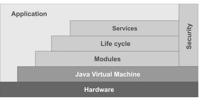
Figure 2.1: OSGi architecture
Listing 2.1 shows an example bundle manifest definition with the described metadata. The OSGi framework builds its layered architecture on top of the JVM. The architecture is displayed in Figure 2.1. As already mentioned, in terms of OSGi, a module is equivalent to a bundle. The definition of bundles as single units of modularization forms theModule Layer of OSGi. It ensures and resolves fine-grained dependencies for bundles, adds explicit information hiding and provides a more sophisticated class loading concept than standard Java.
The Life Cycle Layer defines the execution-time management of the modules and provides
an Application Programming Interface (API) for this purpose. With the defined life cycle of bundles, it is possible to dynamically install, start, update, stop, and uninstall bundles during the runtime of the application, i.e., without a restart. On the one hand, the Life Cycle Layer
allows the application and the administrator to manage the bundles. On the other hand, it provides an API for the bundles to register and hook into the framework in a well-defined way.
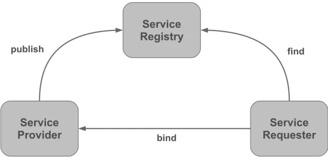
TheService Layer extends the modularization with concepts of service-oriented computing. It
has a central service registry, so bundles can register the services, which they provide. The application can dynamically request these services from the registry. Basically, this is an implementation of the Publish-Find-Bind interaction pattern in Figure 2.2. Internally, the OSGi services are Java interfaces. At first glance, this is nothing new to the Java world. This approach with Java interfaces is very familiar to the developers and it fits into the language structure. The real benefit of the service registry comes from the combination with theLife
Cycle Layer andModule Layer. Service providers are managed dynamically as bundles. They
can be added and removed while the application is running. This provides more flexibility and modularity for Java-based applications.
Figure 2.2: Publish-Find-Bind interaction pattern
TheSecurity Layer is based on Java 2 security and extends it with additional functionality
for bundles. It provides two main functionalities. The first one defines how bundles can be securely packaged and digitally signed. The second functionality defines the security options during the runtime, i.e., the permissions of a specific bundle. The Security Layer in OSGi is optional and will only run on Java platforms, which provide the necessary Security APIs.
OSGi solves many of Java’s limitations in modularity. It provides a precise module def-inition with explicit information hiding, dependency control, life cycle management, and much more. The main downside of OSGi is that it is not a part of the Java standard and it requires an additional custom framework on top of Java. Additionally the configuration and management effort will usually increase firstly with an OSGi framework before you can profit from a better modularity.
Project Jigsaw
Besides OSGi, efforts have been made as well in order to introduce modules as a part of a Java standard. Java Community Process (JCP) defines a formalized process for extending of Java and its standard libraries. Single propositions are managed in so called Java Specification Request (JSR)s. Before a proposition is finally accepted and applied to Java, a team of experts is formed around a JSR. This team is responsible for the specification and the creation of drafts.
In 2005 JSR 277 [Buckley et al., 2006] was announced. Its purpose was to bring a module framework with a defined packaging format and a central module repository into Java. In 2006 JSR 294 [Buckley et al., 2007] was announced with the objective to extend Java with
2.1 Software Module
a superpackage notion, which could group normal packages into modules with specified information hiding. This approach was then changed in favor of JSR 277. So JSR 294 attempts now to define a module-level access modifier, which is compatible with JSR 277. Unfortunately JSR 277 is on hold since 2008 and JSR 294 made only little progress since then.
Meanwhile, Sun Microsystems introduced Project Jigsaw [OpenJDK, 2013] for a standard module system in Java. Originally Project Jigsaw was planned to be officially included in Java 7. However, this didn’t happen and lastly it was announced for Java 9 in 2015 [Reinhold, 2012]. Project Jigsaw targets on extending Java with modules so that they are part of the language construct. In terms of Project Jigsaw a module is defined as followed:
A moduleis a collection of Java types (i.e., classes and interfaces) with a name,
an optional version number, and a formal description of its relationships to other modules. In addition to Java types a module can include resource files, configuration files, native libraries, and native commands. A module can be cryptographically signed so that its authenticity can be validated.
[Reinhold, 2011] Project Jigsaw will add the keyword module to Java and allow by convention to store the definition of modules in a module-info.javafile for a compilation unit. The only required information is the module name, which is a qualified Java identifier (comparable to Java packages). Dependencies are managed with the keywords exportsand requireswithin the module definition. So a module can explicitly define with the exports keyword which parts are externally exposed in order to ensure information hiding. The requireskeyword defines on which functionalities a module depends. Executable modules may define an entry point with a classkeyword and an explicit path to a class with a public static void mainmethod. In addition, Project Jigsaw allows defining service providers and service consumers. A service within Project Jigsaw is a Java interface or abstract class. A module can define which service implementation it provides byprovides service, following service name, and then thewith keyword followed by the path of the service implementation. Therequires servicekeywords followed by the service name designate a module as a service consumer. Listing 2.2 shows an example module definition with the concepts previously discussed.
Project Jigsaw will solve many modularity issues in Java comparably to OSGi. In fact, there are many parallels to OSGi. The module definition of Project Jigsaw is comparably powerful as the
Module Layer of OSGi and provides quite similar features, e.g., module versions, dependencies,
entry points, etc. In Project Jigsaw modules can be cryptographically signed like in the
Security Layer of OSGi. Even the services from Project Jigsaw can be found in OSGi on the
Service Layer with the same terminology.
Still, there are many differences in detail and some major differences between Project Jigsaw and OSGi. On the one hand, the major benefit of Project Jigsaw is that it extends the Java language construct itself. So there is no need for a custom framework on top of Java. On the other hand, there are some drawbacks about Project Jigsaw. It is still a draft, so it is will be released at the earliest with Java 9. TheLife Cycle Layer of OSGi is more powerful because it
Listing 2.2 Example Project Jigsaw module definition in a module-info.java file.
/**
* UniMoDoc HTML Exporter
* A bundle for HTML export of documentation * (c) 2013, University of Stuttgart */ module de.unimodoc.export.html @ 1.0.0 { requires de.unimodoc.core @ >= 1.3.0; exports de.unimodoc.export.html; class de.unimodoc.export.html.Activator
provides service de.unimodoc.export.Exporter with de.unimodoc.export.html.HTMLExporter; requires service de.unimodoc.export.ExportSettings;
}
allows adding and removing modules during the runtime of applications, what is explicitly not planned by Project Jigsaw. Another fundamental difference between these two approaches is that Project Jigsaw aims also to modularize the Java Runtime Environment (JRE) itself. When Project Jigsaw will be released, many applications will still use OSGi. Also, due to the different features it might be beneficial in some cases to use both approaches from OSGi and Project Jigsaw. This will require interoperability or at least tolerance between these approaches. Project Penrose [Ellison, 2013] aims to solve these issues.
2.1.2 Software Modules Conclusion
The previous sections show that in practice even for a specific language there can be different interpretations of a module. This is especially the case if the language itself provides no distinct construct for module support like Java. At the same time efforts like OSGi and Project Jigsaw demonstrate that there is a need for modularization beyond the default capabilities of Object Oriented Programming (OOP) in Java. These different approaches illustrate also that there are various degrees of modularization. They provide dissimilar capabilities and features of modularization and therefore can be useful in various use cases depending on requirements.
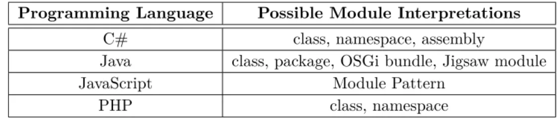
This confusion in terms of modules appears not only in Java. In C# OOP constructs like class or namespace (comparable to package in Java) and assemblies from the Common Language Infrastructure (CLI) can also be assumed as modules. The CLI assemblies are compiled code libraries with a manifest, versioning and security settings. They are deployable units comparable to OSGi bundles in Java.
There are also programming languages which support no modularization with a specific lan-guage construct at all, e.g., JavaScript. Instead, in order to achieve modularity in JavaScript often variations of a Module Pattern [Stefanov, 2010] are used to encapsulate functions and data with an interface in a closure. Table 2.1 shows a set of languages paired with an incomplete list of possible module interpretations.
2.1 Software Module
Programming Language Possible Module Interpretations
C# class, namespace, assembly
Java class, package, OSGi bundle, Jigsaw module
JavaScript Module Pattern
PHP class, namespace
Table 2.1: Module interpretations in different programming languages
In conclusion, there are different approaches and degrees of modularity in practice. Therefore, it is hard to find a general and precise definition of a module to cover and identify all the possible variations. These variations are on their own rights and useful in different use cases depending on particular requirements. Due to these findings this thesis will stick to a very general IEEE definition of a module:
module A logically separable part of a program.
[IEEE-610.12, 1990] As a result, a tool for documenting software modules should be able to handle different kinds of modules. Even a tool for documenting modules of only one programming language like Java will inevitably come across various kinds of modules. It is also usually not possible to define a finite set of those module types. This is especially the case because software projects in practice are not limited to a single programming language, but are multilingual, i.e., they contain a mixture of programming languages. For example, a single web-based software project can contain a mixture of Java for application back end, Structured Query Language (SQL) for database operations, JavaScript for front end, and ActionScript for complex visual effects in the front end. This leads this thesis to a requirement for a module documentation tool, being generic enough to handle various types of modules in different programming languages.
2.2 Software Architecture Documentation
Software architecture describes the high-level structure of software, its components, interfaces, relations, etc. This information is required by different stakeholders, e.g., customers in order to ensure the requested requirements and quality is delivered, implementers in order to understand and build the system, testers in order to create and run tests, etc. There is no unified definition for software architecture similar to modules. In fact, the Software Engineering Institute (SEI) has a collection of over 150 definitions for the term software architecture on its website [SEI, 2013]. This thesis will stick to the IEEE definition:
Software architecture - The fundamental organization of a system embodied in
its components, their relationships to each other, and to the environment, and the principles guiding its design and evolution.
[IEEE-1471, 2000] Comparable to the definition of software architecture there is no unified way for documenting software architectures and no standard structure for it. Still, there are some generally accepted approaches for documenting software architectures. One of these approaches is the view concept. Usually it is not possible to describe the complete software architecture in one dimension only. Therefore, different views are used in order to describe the software architecture from different perspectives. IEEE defines the view as follows:
View- A representation of a whole system from the perspective of a related set of concerns.
[IEEE-1471, 2000] For a specific software architecture there are various possible views and it is in the responsibility of the software architect to choose the relevant ones. In the past, some view categories have proved to be successful for many software architectures. Sometimes these view categories have different naming in the literature, but the meaning is almost the same. This thesis uses the naming from [Garlan et al., 2010]. In [Garlan et al., 2010] the three view categories are called Module Views, Component-and-Connector Views, and Allocation Views. These view categories are described in the following way.
Module viewsdivide the whole system into single modules in terms of Chapter 2.1 and define
their relationships to each other. Such relations between the modules are Is part of,Depends on, and Is a. There are various possible notations to describe the Module views. Informal graphical and textual notations face a variety of formal notations, e.g., UML, Dependency Structure Matrix (DSM), ER diagram, etc.
The Module views answer several purposes. They provide a plan for building the source code and the modules can usually be mapped to a set of source code artifacts. The single modules always implement a functionality which is part of the system requirements. As a consequence, all modules of a Module view implement all the functional requirements. Therefore, one can analyze whether the architecture meets the requirements. In addition, the Module views are
2.3 Templates and Tools for Software Architectures
some kind of communication vehicle. Depending on their granularity, they can serve as a starting point for understanding and learning the complete system.
Component-and-Connector (CaC) viewsrepresent the system during the runtime. In
[Garlan et al., 2010] the single elements of such views are called components, e.g., objects, processes, etc. The relations between them are called connectors, which represent communica-tion, protocols, interaccommunica-tion, data flow, etc. Sometimes components can be mapped to modules but not necessarily. Comparably to the Module views, CaC views can be represented as well with various informal graphical and textual notations, as with formal notions, e.g., UML, Architecture Description Language (ADL)s, etc.
CaC views show which parts of the system exist during the runtime and how they interact together. This information is essential to address issues of parallelism, timing, communication, performance, availability, reliability, and others. CaC views are meant for modelling and solving of those issues in order to meet the functional and non-functional requirements.
Allocation views show how modules from the Module views or components from the
CaC views can be mapped on single parts of a particular environment. Possible environment can be the hardware on which the software will run or the organization structure of the people, who will implement the software. Depending on the actual view, the relations between modules or components and environmental parts have the semantics of Allocated-to. Besides the informal notions, Allocation views can be represented with UML. In case of a work assignment view, a tabular notation is conceivable.
The Allocations views are useful for estimating and analyzing whether the requirements of software can be met in the corresponding environment. That way issues from the analysis (e.g., performance bottlenecks) can be discovered and resolved. In case of mapping the software on hardware for deploying or installing, Allocation views can be used for creating build and deployment plans.
This thesis focuses on the software architecture documentation especially form the Mod-ule views perspective. It assumes that the modMod-ules are primarily defined and documented by the architect in the software architecture documentation. The modules from the Module views contain a mapping to the actual source code artifacts. This way the overview information of a module can be found in the software architecture documentation and the fine-grained implementation details of the source code artifacts are linked from the overview. The result is a complete documentation of modules. Since the module documentation is part of the software architecture documentation, their stakeholders are the same. The complete list of software architecture documentation stakeholders is listed in Table A.1.
2.3 Templates and Tools for Software Architectures
The lack of standard structure for software architectures is an issue. Each time new software architecture is created a suitable and commonly accepted structure needs to be found. This cause additional time expenditure. Finding and understanding relevant information for readers
is more time consuming. Learning and especially copying from approved software architectures is more complicated.
Therefore various templates for software architectures exist, which try to solve these issues [arc42, 2013], [Garlan et al., 2010], [IEEE-1471, 2000], [Knöpfel et al., 2005], [FMC, 2013], [FEA, 2013], [MODAF, 2013], [TOGAF, 2013], [RM/ODP, 2013]. They prevent from rein-venting the wheel and usually provide a tried and tested basis. Software architecture templates are typically simple documents created with a word processor. As an example, [Starke and Hruschka, 2011] proposes a template which is delivered as a Microsoft Word file. However, word processors are not sufficient for creating software architecture documentation and templates for those because they do not provide support for structured input and relations between the single parts of the document. Such templates contain headings for the single document parts and provide free text support only. Forms are better applicable for this kind of documents and templates because they benefit the structure, simplify the input procedure, and are less time consuming during the input. Clear relations between the document parts are essential, e.g., to track down which requirements are implemented and by which software parts, to identify the dependencies between modules, or to find out where are the corresponding source code artifacts for a particular module. Unlike free text, forms are well suitable for input of such relations. Moreover, the software architecture documentation should be in the revision control like the source code artifacts and other software documents. Files generated by word processors, e.g., Microsoft Word or Apache OpenOffice are binary. Thus they are not suitable for revision control tools like SVN or Git. The differences in versions cannot be compared automatically and therefore not efficiently merged.
Beside the word processors there is only little tool support for documenting software ar-chitectures. Tools for UML and other formal notations are not sufficient for documenting complete software architectures because they support only the illustration of a solution but not the reason. A software architecture documentation needs to list the requirements (or at least to reference them), present the solution, and to argue the reasons, why this is a suitable solution. For a single issue numerous solutions might exist. Each of which is a trade-off against the requirements. Therefore the architect needs to depict an argumentation for a solution. Software architectures are usually structured as normal text documents. Formal notation tools are used in addition for diagram creating. Single software architecture documentation can contain diagrams in different formal notations, e.g., UML for Java classes and ER diagrams for database tables.
Another category are Web-based documentation tools. Hyper-linking between single pages eases the navigation in the documentation and solves the issue of missing relations between document parts of word processor files. [Garlan et al., 2010] suggests especially wikis for Web-based software architecture documentation. Wikis allow parallel editing and a central repository of documentation for different users. Various stakeholders can work on different parts of the documentation in parallel and create it together. The drawbacks of wikis are that they need to be accessible from the Web or Intranet and they provide no structured form-based input like word processor files. Moreover, [Starke and Hruschka, 2011] notes that wikis tend to grow into information graves. If various stakeholders can contribute in an uncontrolled amount to the documentation, it can easily lose its clarity and relevance.
2.4 J-PaD
2.4 J-PaD
This thesis is partially based on results and findings of [Kircher, 2012]. In his diploma Kircher points out the relevance of module specification and documentation in software development and created J-PaD [J-PaD, 2013], an Eclipse based tool for module documentation. The following section describes the above mentioned research in more detail and shows the relevant differences.
Figure 2.3: Bathtub Curve from [Kircher, 2012]
Kircher refers to his interpretation of the Bathtub Curve in Figure 2.3. It shows the different abstraction layers during the software development. According to him, the left-side of the chart describes the top-down approach (usually used during the development) and the right-side describes the bottom-up approach (usually used during the testing). Activities of the same abstraction layer are horizontally interconnected. Further, he argues that the objectives from the overall software specification and design are used for system testing and integration testing. Still, there is need for module specification and documentation in order to test on a lower level, e.g., single modules, unit testing, etc. Kircher concludes this type of documentation as part of the source code. His examination of the available tools for source code documentation shows their lack of module support. As a consequence of the missing tool support, Kircher develops within the scope of his research J-PaD. In the scope of his research and this tool he assumes Java packages as modules but provides no further explanation for this decision. J-PaD is integrated in the Eclipse Integrated Development Environment (IDE) and provides a simple way to create module documentation with predefined data fields. The input is stored in the package-info.javafile. This is a standard description file for packages in Java. Data which is not part of Javadoc is stored in an additional comment field below the header comment. The structure of the module documentation is configurable by a schema file.
This thesis only partially agrees on Kircher’s interpretation of the Bathtub Curve and his conclusion. The original statement of the chart in Figure 2.4 notes: The sooner a fault is made
Figure 2.4: Bathtub Curve from [Ludewig and Lichter, 2007]
during the software development, the later it will be usually discovered, typically on the same abstraction layer. The fact that a fault made in source code typically can be discovered with unit testing, does not imply that unit tests themselves are only derived from the information out of the source code. This also does not mean that the module documentation is necessarily located on the code level. And it does not imply that the module documentation is only relevant for module testing. On the contrary, information from the module documentation like dependencies or interfaces of modules is required first of all for integration testing.
This thesis assumes software architects as the initial authors of module documentation and in this point it is even consistent with the research of Kircher. Different from his conclusion, this thesis considers module documentation as part of the software architecture.
Another important difference to Kircher’s research is the definition of a module. As already discussed in Chapter 2.1, this thesis does not limit modules to Java packages.
This thesis will address the relevance of module specification and documentation in soft-ware development pointed out by [Kircher, 2012]. It will also apply some of the identified metadata from [Kircher, 2012] for describing modules in a new tool and extend these meta-data. In contrast to [Kircher, 2012] this thesis provides a more general definition of modules described in Chapter 2.1 and support various programming languages, not Java only. Unlike [Kircher, 2012] this thesis will also move the focus from software developers and documenta-tion on the code level to software architects and software architecture level as described in Chapter 2.2. This way the module definition and description is placed within a central and accepted document, fits in its structures, links the source code artifacts, and builds a complete documentation of modules. Compared to [Kircher, 2012], the documentation on the software architecture level extends the interested audience in module documentation to the stakeholders of software architecture documentation in Table A.1.
3 Requirements and Design
This chapter defines the requirements for a module documentation tool called Universal Module Documenter (UniMoDoc) that is based on the results of Chapter 2. Further this chapter describes a general design for such a tool, which will take into account and solve the previously defined requirements.
3.1 Requirements
This chapter contains the requirements for a software architecture documentation tool. The requirements are split into functional and non-functional requirements. They are based on the initial problem statement of this thesis and the research results of Chapter 2.
3.1.1 Functional Requirements
This part describes the required functions of the software.
Tool for creating module documentation
The resulting tool supports documentation for modules. This is an initial requirement for this thesis.
Tool for creating and editing software architecture documentation
According to the argumentation in Chapter 2.2, the documentation of modules is part of the software architecture. Furthermore, the research shows a lack in tool support for software architectures. Module documentation in terms of Module views is related to other views. Therefore, it is reasonable to create a general tool for software architecture documentation in order to document the modules.
Still, the focus of this thesis lies on the module documentation. Due to the limited time frame for a diploma thesis of six months, this focus results in a rudimentary support for other software architecture parts.
Form-based Graphical User Interface (GUI)
The GUI of the tool is form-based in order to ease and structure the input of the user.
Definition of module metadata
In order to document modules, common metadata for the description of modules is required. These metadata are defined and supported by the resulting tool.
Template support
The resulting tool supports templates. New templates can be created, saved and loaded within a tool. The templates provide a structure and example data for a complete software architecture document or single parts of it.
Module documentation template
The defined metadata for module documentation are provided as a template in the resulting tool.
Support of different programming languages
Unlike [J-PaD, 2013], the resulting tool is not limited to a specific programming language or module construct.
Documentation structure support
The documentation created by the resulting tool has a structure. The structure of documentation is required to divide it in logically related parts and to prescribe a specific structure in a template.
Relations between document parts
It is possible to crosslink the different parts of the document. This is required for a better navigation within the document and for the support of relations required by software architecture documentation as described in Chapter 2.2.
Documentation exportability
The design of the resulting tool supports interfaces for export functionalities. Thus export format for the documentation can be easily added.
Function for including graphics
It is possible to embed graphics like UML diagrams in the documentation.
References to external data
The resulting tool supports references to external data like source code files, test cases, images, etc.
Multilingual support
The resulting tool is designed and implemented in a way that allows to extend it for other languages, e.g., by externalizing the strings in property files.
Line-based format
All created data and templates of the tool are saved in a textual line-based format in order to ensure best possible compatibility with revision control tools like SVN.
Java tool
3.1 Requirements
3.1.2 Non-functional Requirements
This part denotes the quality requirements of the software.
Extensible GUI
The GUI is as well and easy extensible as possible.
Extensibility for other software architecture documentation parts
The focus of this thesis lies on the module documentation and other software architecture parts are only rudimentary supported. Therefore, it is important that the resulting tool can be easily extended in order to better support the other parts of software architecture. This is achieved by foresighted design, defined extension points and good documentation.
Good maintainability
The tool is as well maintainable as possible by providing a good documentation and simple extensibility.
Good usability
The resulting tool provides good usability by intuitive user guidance and clear messages.
3.1.3 Stakeholders
The stakeholders of UniMoDoc consist of two groups, which correspond to following use cases.
Documenting and using software architectures
In the first place the stakeholders of UniMoDoc are equal to the stakeholders of the software architecture documentation. Thus software architects may use UniMoDoc for documenting software architectures. Furthermore, they can create and share templates. Implementers can use UniMoDoc in order to understand and learn the entire software system or its parts from the documentation. Architects may communicate with implementers via the documentation by noting implementation advices and constraints. In addition, UniMoDoc supports explicitly testers with extensive test documentation for modules covered in [Casciato, 2013]. The complete overview of software architecture documentation stakeholders is denoted in Table A.1. The use of UniMoDoc for documenting software architectures does not require specialized knowledge.
Extending UniMoDoc
Every person who may extend UniMoDoc is regarded as a stakeholder. Therefore, UniMoDoc provides numerous extension points. Extending the tool requires knowledge in Java software development.
3.2 Design
This chapter takes into account the current state of the art from Chapter 2 and describes the concepts for solving the requirements from Chapter 3.1. Some of the requirements prescribe a technological frame. Still, the design is kept intentionally abstract. Therefore, it can be easily ported to other technologies or context.
Firstly, this chapter describes the general concepts of this thesis in 3.2.1 Concepts. It provides a high level overview of the concepts mainly from the perspective of the potential user, keeping the most technical details in background. Secondly, this chapter suggests a data model on a technical level in 3.2.2 Data Model, which was taken as a basis for the implementation. Finally, this chapter defines the relevant metadata for modules in 3.2.3 Module Metadata. This collection of metadata can be aggregated to a module documentation template. An example module documentation template using these metadata are suggested in the implementation part in Chapter 4.
3.2.1 Concepts
Chapter 3.1 describes the requirements and defines that the resulting tool should support creating and editing software architecture and module documentation in particular. Chapter 2.3 shows the lack of specialized tool support for software architecture. Instead of specialized tools, word processors are often used to create software architecture. However, word processors provide only poor functionality to crosslink the single parts of the document among each other and with external resources, e.g., source code, test data, and other documents. They are not well suitable for common revision control tools due to the binary formats. Furthermore, they do not support complex and structured data input but free text only. The basic idea behind the concept of this thesis is to build on the established and well-known approaches of the word processors and to overcome their disadvantages at the same time. In this manner, users can apply their accustomed procedures to the new tool and get started faster.
Document
The document is a metaphor for the complete file containing the software architecture docu-mentation. The name of the document results implicitly from the file name. The document is the top level element in the structure and bundles all other sub elements, which are discussed in the next paragraphs.
Chapters
One basic element of the document structure is the chapter. The chapter is also adopted as a metaphor of a document part from the word processors. It bundles related information below a caption. Chapters are hierarchical. They always have exactly one parent, which is either the document or another chapter. Furthermore, chapters can have zero or more children chapters.
3.2 Design
UniMoDoc File Edit View Help
Document 1 Requirements 1.1 Functional Requirements 1.2 Non-functional Requirements 2 Modules 2.1 Controller 2.2 Events 2.3 Model 2.1 Controller 1 2 3 5 4
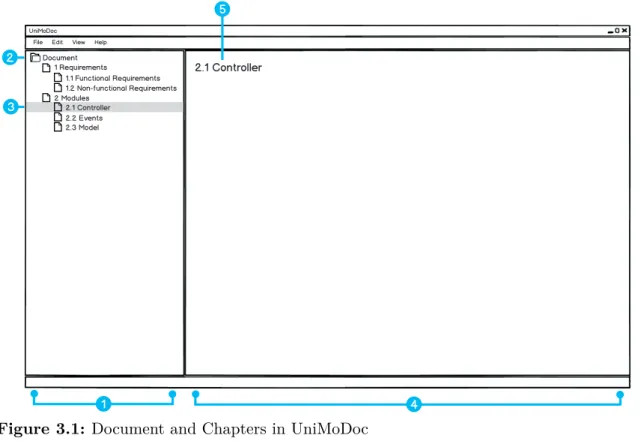
Figure 3.1: Document and Chapters in UniMoDoc
Item 1: Document Structure, Item 2: Root Element, Item 3: Selected Chapter,
Item 4: Content Area, Item 5: Name of the Selected Chapter
Since chapters are generic elements and they can be nested freely, this approach can realize various structures.
In addition to it, chapters have a number identifying the position of the chapter in the document structure. It is recursively compound of the order numbers of parent chapters. The described information is represented in Figure 3.1.
Figure 3.1, Item 1 on the left-hand side shows the hierarchical structure of the document in a tree pane. That way the user can oversee the complete structure of the document, navigate through it, and keep track of the current location in the structure. Figure 3.1, Item 2 points to the root of the structure, which is the document itself. Figure 3.1, Item 3 illustrates a selected chapter in the document structure. In this case, the currently selected chapter is
2.1 Controller. Its content is displayed in the content area (cf. Figure 3.1, Item 4) on the
right-hand side. The content area is meant to display the contents of selected chapters and make them editable to the user. In the top of the content area the caption of the selected chapter is placed (cf. Figure 3.1, Item 5).
This concept allows the user to navigate, view, and edit the document simultaneously. Similar navigation concepts are well-known from file managers (e.g., Microsoft Windows File Explorer [Microsoft, 2013a], Apple OS X Finder [Apple, 2013], etc.), Portable Document Format (PDF)
readers (e.g., Adobe Reader [Adobe, 2013], Foxit Reader [Foxit Corporation, 2013], etc.), IDEs (e.g., Eclipse [Eclipse Foundation, 2013a], Microsoft Visual Studio [Microsoft, 2013b], etc.), and therefore are familiar to many users.
Sections
Chapters partition the document into logical parts and provide a coarse-grained structure. Thus chapters are groups of related information and they are not atomic. Therefore, sections provide a finer granularity level of structure. Sections partition the chapters into atomic information chunks. Consequently, unlike the chapters, these chunks are not hierarchical. Still, there are many similarities between chapters and sections. Sections are also logical parts of the document but on a lower level. Comparably to the chapters, they have a caption and an order. The order of the sections in the document is implicit because the number is not displayed to the user but regarded internally. Both, chapters and sections have contents. While the contents of the chapters are the sections, the contents of the sections are discussed in the next paragraph.
Widgets
The content of a single section has a specific data type. It can be a simple text, markup language, programming language, date, image, reference to another file, and many others. Therefore, a section needs to render the content and make it editable to the user somehow. At this point the widgets come into play. Widgets are visual components, which do exactly this job. They are bound to sections, render their data types, and make the data types editable to the user. Since the content of a section cannot be displayed to a user without an applicable widget, each section needs exactly one widget. Therefore, a single widget needs to support at least one data type.
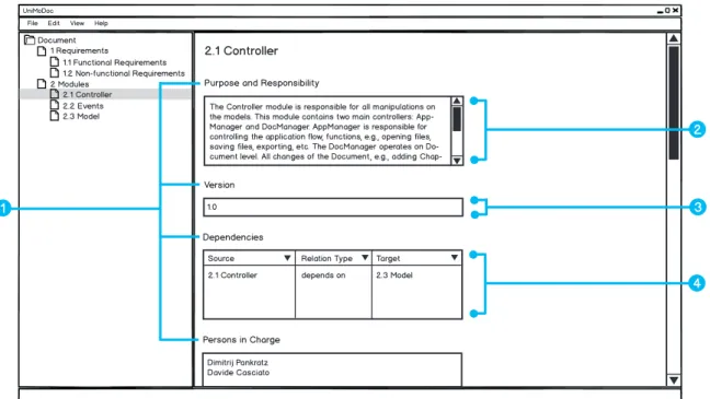
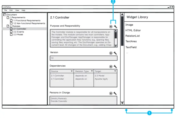
Figure 3.2 shows how chapters, sections, and widgets are combined together. Purpose and
Responsibility,Version,Dependencies, andPersons in Charge are names of the sections (cf.
Figure 3.2, Item 1). The sectionPurpose and Responsibility uses a TextArea widget to display the content (cf. Figure 3.2, Item 2). TextArea widgets are meant to display long textual contents. The Version section uses instead a TextField widget (cf. Figure 3.2, Item 3).
TextField widgets are similar toTextArea widgets, but display the text in one line. In the case
of the Dependecies section, the used widget isRelationList (cf. Figure 3.2, Item 4). It is able to display links to other document parts and more. RelationLists will be explained later in detail.
Technical Details of Widgets
This part of the thesis will describe the technical details of the widgets using the example of
TextArea and TextField. The internal data type consumed by these widgets is the same. It is
3.2 Design
UniMoDoc File Edit View Help
Document 1 Requirements 1.1 Functional Requirements 1.2 Non-functional Requirements 2 Modules 2.1 Controller 2.2 Events 2.3 Model 2.1 Controller
Purpose and Responsibility
Version
Persons in Charge
The Controller module is responsible for all manipulations on the models. This module contains two main controllers: App-Manager and DocApp-Manager. AppApp-Manager is responsible for controlling the application flow, functions, e.g., opening files, saving files, exporting, etc. The DocManager operates on Do-cument level. All changes of the DoDo-cument, e.g., adding
Chap-1.0
Dimitrij Pankratz Davide Casciato Dependencies
Source Relation Type Target 2.1 Controller depends on 2.3 Model 1
2
4 3
Figure 3.2: Sections and Widgets in UniMoDoc
Item 1: Names of the Sections, Item 2: TextArea Widget, Item 3: TextField
Widget, Item 4: RelationList Widget
where more than one widget is applicable to a specific data type, it is possible to change the widget of a section dynamically during the runtime without affecting the content.
The widgets and data types are meant to be easily extensible. In order to achieve this extensibility common interfaces will be provided. Due to this extensibility, it is necessary to consider that a file may use unknown widgets and data types. There are various possibilities how to handle this issue. This thesis suggests defining a default fall back widget, i.e., aTextArea
widget. Due to the requirement that all generated files of the application are text-based, it is consequently possible to represent the content of all data types as text. In case no applicable widget is found for the data type, the content can be still represented as raw text in aTextArea
widget.
In consequence of the requirement for various export formats widgets will need to render the content of a section not only in the GUI of the application but also for all export formats. If a widget does not support a specific export format, it can still return the content as text. This behavior is guaranteed by the common interface for widgets.
In addition, it is convenient to provide a configuration for widgets, which is unique for each widget instance. That way the user can configure each widget instance in a desired way, e.g., the maximum length of the text in a TextField widget or validation rules for the input. These configurations need to be considered in the common interface of the widgets.
UniMoDoc File Edit View Help
Document 1 Requirements 1.1 Functional Requirements 1.2 Non-functional Requirements 2 Modules 2.1 Controller 2.2 Events 2.3 Model 2.1 Controller
Purpose and Responsibility
Version
Dependencies
Persons in Charge
The Controller module is responsible for all manipulations on the models. This module contains two main controllers: App-Manager and DocApp-Manager. AppApp-Manager is responsible for controlling the application flow, functions, e.g., opening files, saving files, exporting, etc. The DocManager operates on Do-cument level. All changes of the DoDo-cument, e.g., adding
Chap-1.0
Dimitrij Pankratz Davide Casciato
Source Relation Type Target 2.1 Controller depends on 2.3 Model
Relations Relation Types Name Description Style depends on The depends...
2 3 1 4 2.1 Controller 2.3 Model depends on
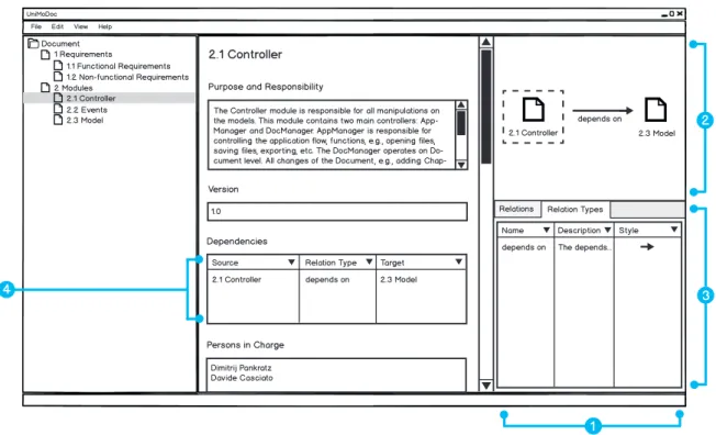
Figure 3.3: Relation and Relation Types in UniMoDoc
Item 1: Central Relation Management Area, Item 2: Visualization of Relations,
Item 3: Relation Tables, Item 4: Relations in the RelationList Widget
Relations and Relation Types
In the software architecture documentation relations can reveal, which modules realize a requirement, they define how the different views are connected, show the dependencies between modules, etc. In word processors these relations are often only implicit. There are textual references but the user cannot navigate along these relations.
Even if the user can navigate along these relations, the navigation is often only unidirectional, e.g., a module A depends on module B, this information is denoted in the description of module A but not in the description of module B. In this case, it is cumbersome to find out, which modules depend on module B from the perspective of module B.
In addition, the relations have always a specific semantics. In the example of module A, which depends on module B, the dependency can carry an additional semantic. It can be required, optional, or module A might realize the abstract module B, etc. If the relation is not explicit and formal, the semantic might be ambiguous and not obvious.
Word processors provide no central management or overview about these relations. The relations are spread across the document. It is not possible to find or filter the relations by their semantics.
3.2 Design
These issues can be solved with an explicit relation definition, relation types encapsulating the semantics, and a central management for the relations. Figure 3.3 puts it all together. It demonstrates how relations can be managed using the example of a depends on relation between the modules 2.1 Controller and 2.3 Model. The content area makes room for the central relation management (cf. Figure 3.3, Item 1). This central relation management is separated vertically into the Relation Visualization (cf. Figure 3.3, Item 2) and Relation
Tables (cf. Figure 3.3, Item 3). The Relation Visualization shows all inbound and outbound
relations of the currently selected chapter to the user. The currently selected chapter in the visualization is highlighted with a dashed border around it. In Figure 3.3 it is 2.1 Controller. The visualization shows here the outbound relation to module 2.3 Model with the relation
type depends on. If the user selects 2.3 Model as current chapter, the visualization will show
the same relation as inbound for the selected chapter 2.3 Model.
TheRelation Tables are displayed in tabs. There are two tabs in Figure 3.3, Item 3: Relations
andRelation Types. TheRelationstab contains a tabular listing of all relations in the document.
In addition, this and other tables can be filtered to show only the relations of the currently selected chapter or they can be filtered various other ways. The Relation Types tab contains a table of all relation types in the document. Thus it lists the semantics of relations and how they are displayed inRelation Visualization. Relations, relation types, and the visualization of them are discussed in [Casciato, 2013] in detail.
Linking Relations
A central relation management is useful in order to overview and manage the relations of the complete document or parts of it. Still, in some cases it is convenient to view and manage relations directly from the content area of a chapter. If the document is exported in other formats like PDF or Hypertext Markup Language (HTML), e.g., all relations can be printed at the end of the document or all relations of a chapter at the end of the corresponding chapter. The user might want to place the relations or a selected group of relations in a specific section. In that case a RelationList widget can be used to do this. The RelationList widget links existing relations and lists them in a tabular view. Figure 3.3, Item 4 illustrates how the
RelationList widget is displayed. This approach allows defining views on existing relations
comparable to the views concept in databases. In addition, it provides a quick access to context-sensitive relations directly from the widget. This means that the user can add, edit, delete, link, and unlink relations from theRelationList widget.
External References
In order to satisfy the requirement for external references, it is not sufficient to reference only across the document parts. Modules may depend on external libraries. UML diagrams, source code artifacts, test cases, protocols, and other external resources need to be referenced somehow from the document. It is essential to provide relations between document parts and external references. Yet discussed relation endpoints are chapters and sections. They need to be extended by external references. In order to achieve this, it is necessary to represent
UniMoDoc File Edit View Help
Document 1 Requirements 1.1 Functional Requirements 1.2 Non-functional Requirements 2 Modules 2.1 Controller 2.2 Events 2.3 Model 2.1 Controller Purpose and Responsibility
Version
Dependencies
Persons in Charge
The Controller module is responsible for all manipulations on the models. This module contains two main controllers: App-Manager and DocApp-Manager. AppApp-Manager is responsible for controlling the application flow, functions, e.g., opening files, saving files, exporting, etc. The DocManager operates on Do-cument level. All changes of the DoDo-cument, e.g., adding
Chap-1.0
Dimitrij Pankratz Davide Casciato
Source Relation Type Target
2.1 Controller depends on 2.3 Model
2.1 Controller depends on Apache log4j
Relations Relation Types
Name Type Path
Apache log4j LOCAL file:///C:/Users...
1 References 4 2 3 2.1 Controller 2.3 Model depends on depends on Apache log4j
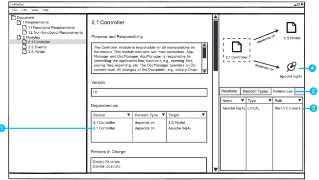
Figure 3.4: External References in UniMoDoc
Item 1: External Reference Entry in a RelationList Widget, Item 2: Tab for
External References, Item 3: External Reference Entry in the Central Reference
Management, Item 4: External Reference in the Relation Visualization
and manage the external references within a document. Figure 3.4 illustrates how this can be done.
In Figure 3.4, Item 1 a new dependency from the 2.1 Controller module is added to an external logging libraryApache log4j. In order to manage the external references, a new tab
References is added to theRelation Tables (cf. Figure 3.4, Item 2). Figure 3.4, Item 3 shows
the external library listed in the tabular view of the external references. The table contains a
Type column, which displays what type an external reference has. There are three possible types: TEXT, Uniform Resource Locator (URL), and LOCAL. References of type TEXT
are useful if no explicit location of the reference is available, e.g., an external module that is not build yet. References of URL type point at an absolute path in URL form. Finally, the references of LOCAL type are meant to point at files, which are located at the same machine as the document file. LOCAL references are handled in a special manner. They can be absolute or relative. Relative references are essential because the document should be under revision control with other files (external references). Thus absolute references cannot be used, since revision control is usually used by different people and machines. Still, relative references are sometimes very impractical. If the user moves the document to another location, all relative references become invalid. Therefore, the location of external references is stored
![Figure 2.3: Bathtub Curve from [Kircher, 2012]](https://thumb-us.123doks.com/thumbv2/123dok_us/8993697.2384190/27.892.88.744.332.563/figure-bathtub-curve-from-kircher.webp)
![Figure 2.4: Bathtub Curve from [Ludewig and Lichter, 2007]](https://thumb-us.123doks.com/thumbv2/123dok_us/8993697.2384190/28.892.163.798.162.400/figure-bathtub-curve-ludewig-lichter.webp)