UAV Pose Estimation using POSIT Algorithm
*1
M. He
, 2C. Ratanasawanya
, 3M
.Mehrandezh,
4R. Paranjape
*1
College of Electrical & Information Engineering, Hunan University, China,
E-mail:[email protected]
2
Electronic Systems Engineering, University of Regina, Canada,
E-mail: [email protected]
3
Associate Professor, Industrial Systems Engineering, University of Regina, Canada,
E-mail:
[email protected]
4
Professor, Electronic Systems Engineering, University of Regina, Canada,
E-mail:
[email protected]
doi:10.4156/jdcta.vol5. issue4.19
Abstract
Vision-based pose estimation is widely employed to Mini Unmanned Aerial Vehicles (MUAV) with limited payloads. The Pose from Orthography and Scaling and Iterations (POSIT) is one of the most important solutions to estimate the pose by 2-D images and 3-D model of objects. In order to evaluate the performance of POSIT algorithm, a test platform that consists of a MUAV, a wireless camera, a computer workstation, and a motion capture (Optitrack) system is developed. The pose of the MUAV is calculated by the POSIT algorithm with a set of 2-D images captured by the on-board camera, and the calculated pose is compared to the actual pose reading from the Optitrack system. The experimental result demonstrates that the error remains within acceptable bounds and the POSIT is a useful alternative for pose estimation of a MUAV.
Keywords
: Pose Estimation, MUAV, Optitrack System, POSIT.1. Introduction
UAVs (Unmanned Aerial Vehicles) recently draw a great deal of attention within the public and private sectors as a useful tool for mitigation, prevention, and timely response to emergency situations. The problem of the object’s position and orientation (aka pose) estimation arises in several domains of application such as localization, visual servoing, object tracking and so on [1-5]. Compared to typical inertial, sonar, atmospheric, and GPS based sensors, camera appears as an ideal sensor for deployment in small UAVs with limited payloads due to its compact size and abundant information in captured images. As a result, vision-based pose estimation methods have been focused in many literatures [6-8]. Current pose estimation algorithms can be classified into model-based [9] and model-free [10] methods depending on the requirement of the knowledge about the 3D target model and the camera parameters.
With the knowledge of both the 3D model of a target object and the feature correspondence between the object and its 2D image, model-based methods estimate the pose of the camera relative to the object by using single view of image. In the case of this method, pose estimation from image points is the most well-known technique. For example, RANSAC (Random Sample Consensus) solved Location Determination Problem from three and four coplanar feature points or six points in general position. Unfortunately, no general result is given about the uniqueness of the solution [11]. Lowe’s algorithm defined an error function to express the distance between image features in physical space and the projection of the corresponding points at the current camera location, and an iterative process is used to correct possible projection error. More accurate result could be obtained from Lowe’s algorithm; however, it is more complex and computationally demanding as well as an approximate pose is needed to initiate the iteration process [12]. The POSIT algorithm estimates the pose of the camera with respect to an object and optimizes the error by using an iterative process. POSIT avoided initial pose estimation and matrix inversion computation, and guaranteed accurate pose estimation. Therefore, it is a simple, efficient, and suitable alternative for real-time applications [13].
With the original version of the POSIT algorithm, the performance evaluation was implemented by using synthetic images of a tetrahedron and a cube. The pose of the objects which were used to produce
the images and the pose of the objects computed by POSIT from the synthetic images were compared. However, the validation of this algorithm was questionable in practice in terms of the pose estimation accuracy. In order to evaluate the performance of POSIT for real-time pose estimation of UAVs, we developed a test platform which consists of a Mini UAV (MUAV), a wireless camera, a computer work station, and a motion capture (Optitrack) system. The pose of the MUAV is calculated by POSIT algorithm using a set of images captured by the on-board camera. The calculated pose is compared to the actual pose reading from the Optitrack system.
This paper is organized as follows. Section 2 presents the components of the method, including the test platform setup, POSIT algorithm, the homogeneous transformation for pose estimation results comparison. Test results can be found in section 3. Section 4 concludes this paper with a brief discussion.
2. Method and Algorithm
2.1. Experimental setup
The POSIT-based UAV pose estimation test platform is shown in Figure 1. The platform consists of a MUAV, the Optitrack system, a computer work station, a wireless video camera, and a 3D object, which is a white cardboard box.
(a) (b)
Figure 1. Mini UAV test setup (a) Optitrack system and Qball-X4 (b) Qball-X4 and the target object The Qball-X4 helicopter is selected as the MUAV [14]. The Qball-X4 is an innovative quadrotor helicopter suitable for a wide variety of UAV research applications. With the help of four motors fitted with 10-inch propellers, it is able to fly under 6 Degrees-of-Freedom (DOF); 3 translational DOF and 3 rotational DOF (roll, pitch, and yaw). The entire quadrotor is enclosed within a protective carbon fiber cage which gives the Qball-X4 a decisive advantage over other vehicles that would suffer significant damage if contact occurs between the vehicle and other obstacles.
A light-weighted wireless camera is attached to the Qball-X4 body for providing real-time images of the target object. The box is attached to the wall in the field of view of the wireless camera. The background is black for the best contrast to the color of the box in Red-Green-Blue (RGB) color space, which makes it much easier to identify the corners of the box as image feature points.
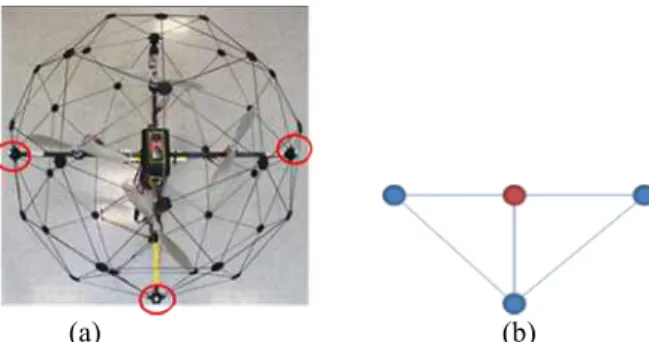
The Optitrack is a motion capture system which tracks the movement of Infrared (IR) reflectors attached to any object in the workspace using 6 IR cameras [15]. These IR cameras are arranged around an approximately 6 cubic meters workspace in which the Qball-X4 moves. The Optitrack system is able to provide the pose of an object defined by a group of IR reflectors relative to the origin of the system’s coordinates. In our experiment, we also chose the coordinate frame of Optitrack system as the reference of the world frame, W. The origin of the workspace coordinates must be defined during camera calibration for the six infrared cameras. To define the Qball-X4 as a trackable object for Optitrack system, three reflectors are attached to the ends of the two cross bars except the front end where the wireless camera is attached as shown in Figure 2(a). Figure 2(b) shows the IR reflectors as seen by the cameras (blue points); the virtual center of gravity (c.g.) of the trackable object is defined during signal processing (red point). The pose of the object is given at c.g. expressed in the world frame.
All signal processing are finished by the work station, including Optitrack cameras and wireless camera calibration, manual feature point selection, pose calculation by POSIT algorithm and so on.
(a) (b)
Figure 2. Trackable object definition for Qball-X4: (a) three reflectors attached on Qball-x4, (b) image of IR reflectors and the vitual c.g.
2.2. POSIT Algorithm
POSIT algorithm was proposed for finding the pose of an object relative to the camera from non-coplanar feature points contained in a single image. It is the combination of two algorithms, namely ‘POS’ (Pose from Orthography and Scaling) and ‘IT’ (Iterations). The ‘POS’ algorithm approximates the perspective projection with scaled orthographic projection (SOP) to find the transformation (rotation and translation) between a coordinate frame attached to the object (object frame) and another coordinate frame attached to the center of projection of the camera (camera frame) by solving a linear system; ’IT’ algorithm is an iterative error optimization operation that updates the parameters of the approximate pose found in the previous step and repeats the POS algorithm several times in order to compute better scaled orthographic projections of the feature points.
With some requirements such as a 3D model of target object, camera intrinsic parameters, a minimum of four non-coplanar image feature points and their relative geometry matched with the corresponding points in the 3D model, the POSIT algorithm calculates the rotation matrix and translation vector of the object with respect to the camera. In other words, POSIT algorithm supplies the transformation information for a point expressed in the object (the box) frame, B, with respect to the camera frame, C. Frame C is attached to the center of projection with z-axis pointing outwards from the camera. Figure 3 shows the diagram of POSIT algorithm. More details about POSIT can be found in the original paper by DeMenthon [13].
Figure 3. Schematic Diagram of POSIT Algorithm
2.3.
Homogeneous transformation
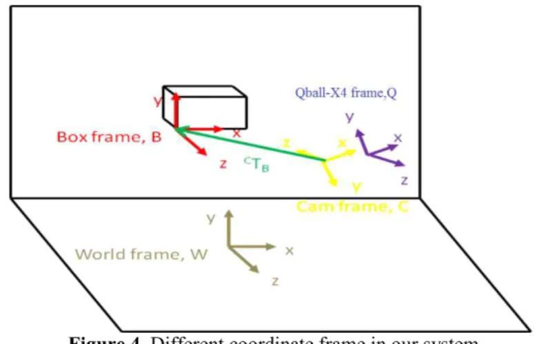
The pose of the Qball-X4 is calculated using the results from POSIT algorithm, homogeneous transformation, and inverse kinematics. As shown in Figure 4, there are 4 coordinate frames in the test setup: the world frame, W, the Qball-X4 frame, Q, which is attached rigidly to the MUAV, the camera frame, C, and the object or box frame, B, attached to the lower front left corner of the box. In order to compare the pose estimation result of POSIT, expressed in frame C, to the pose reading from the
Optitrack system, expressed in frame W, the two coordinate frames need to be aligned using homogeneous transformation.
Homogeneous transformation matrix, ATB, is a matrix which shows how coordinate frame B is
transformed with respect to frame A. It is also used to convert the location of a point between the two frames.
Figure 4. Different coordinate frame in our system The four coordinate frames in the experiment are related as follows:
B C C Q Q W B WT = T T T (1)
WhereWTBis the homogeneous transformation matrix from the box frame to the world frame, Q WT
is the transformation matrix from the UAV frame to the world frame, Q C
T is the homogeneous transfor-mation matrix from the camera frame to the UAV frame, B
CT
is the homogeneous transformation matrix from the box frame to the camera frame.
From (1), W Q T is unknown, therefore:
(
) (
-1)
-1 = Q C B C B W Q W T T T T (2) Where (*)-1 is the inverse operator.The coordinate frame of the box was assumed to have the same orientation as the world frame but differ in translational position, so the homogeneous transformation between them is made up only of the translational component.
ú ú ú û ù ê ê ê ë é -= 1 0 0 0 6727 . 171 1 0 0 1261 . 59 0 1 0 6038 . 18 0 0 1 B WT cm (3)
Because the camera is mounted on the Qball-X4, the transformation between frames C and Q is a known constant: ú ú ú û ù ê ê ê ë é -= 1 0 0 0 385 32 1 0 0 1275 4 0 1 0 0 0 0 1 . . TC Q cm (4)
With the calculation resultC B
T from POSIT, we can obtain the pose of Qball-X4 in the world frame
Q W
T , and the corresponding translation vector and rotation matrix are obtained by inverse kinematics formula.
3. Experimental Results
In order to test the performance of POSIT algorithm for pose estimation of Qball-X4, the MUAV was moved around the workspace and planed randomly in 17 different locations. The box was always kept in the view of the camera at those locations. For each location, the attached cameras records an image of the box, meanwhile the Optitrack system captures the pose of the Qball-X4.
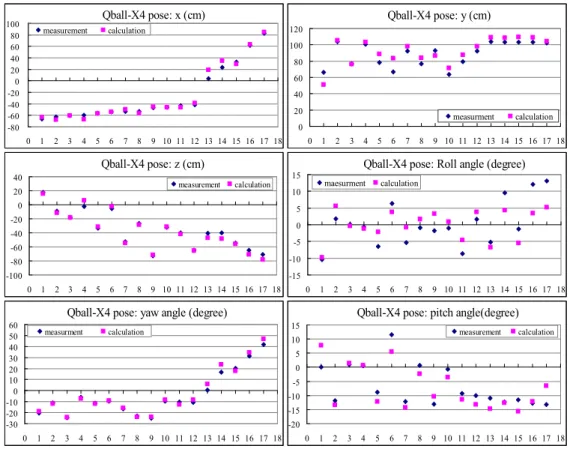
Five corners of the white box were manually detected by the user as non-coplanar feature points needed by POSIT algorithm, the bottom left front corner is the reference point and other four corners from the top side. Since the structure of the box is known as a priory, the pose of the camera relative to the box is calculated by the 3D model configuration of the feature points and their corresponding 2D image coordinates. With the help of homogeneous transformation and inverse kinematics, the Qball-X4 pose is calculated using equation (2), and then the results are compared to Optitrack readings. The x, y, and z coordinates of Qball-X4 are shown in Figure 5, as well as the roll angle around z axis, pitch angle around x axis, yaw angle around y axis. The pink square points are calculation results from Equation (2), which indicate the value from POSIT algorithm. The blue diamond points are the measurements from the Optitrack system.
Qball-X4 pose: x (cm) -80 -60 -40 -20 0 20 40 60 80 100 0 1 2 3 4 5 6 7 8 9 10 11 12 13 14 15 16 17 18 measurement calculation Qball-X4 pose: y (cm) 0 20 40 60 80 100 120 0 1 2 3 4 5 6 7 8 9 10 11 12 13 14 15 16 17 18 measurment calculation Qball-X4 pose: z (cm) -100 -80 -60 -40 -20 0 20 40 0 1 2 3 4 5 6 7 8 9 10 11 12 13 14 15 16 17 18 measurement calculation
Qball-X4 pose: Roll angle (degree)
-15 -10 -5 0 5 10 15 0 1 2 3 4 5 6 7 8 9 10 11 12 13 14 15 16 17 18 maesurment calculation
Qball-X4 pose: yaw angle (degree)
-30 -20 -10 0 10 20 30 40 50 60 0 1 2 3 4 5 6 7 8 9 10 11 12 13 14 15 16 17 18 measurment calculation
Qball-X4 pose: pitch angle(degree)
-20 -15 -10 -5 0 5 10 15 0 1 2 3 4 5 6 7 8 9 10 11 12 13 14 15 16 17 18 measurement calculation
Figure 5. Comparison of Qball-X4 pose estimation results
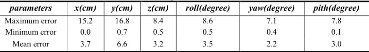
The error comparison results are listed in Table 1, where the maximum, minimum, and mean error of x, y, and z coordinates and error of roll, yaw, and pitch angles can be found. Comparing to the reading of the Optitrack system, the POSIT algorithm gives the pose of camera and hence the pose of the MUAV with less than four degrees rotation mean error and less than 7 cm position error.
Table 1. Relative position errors of 6-DOF
parameters x(cm) y(cm) z(cm) roll(degree) yaw(degree) pith(degree)
Maximum error 15.2 16.8 8.4 8.6 7.1 7.8
Minimum error 0.0 0.7 0.5 0.5 0.4 0.1
Mean error 3.7 6.6 3.2 3.5 2.2 3.0
4. Conclusion
The POSIT algorithm was tested for pose estimation of a MUAV from a set of images containing four non-coplanar feature points of a box. The performance of POSIT is evaluated by comparing to the recorded results from the Optitrack system. The experimental result appears to remain within reasonable error and the POSIT proves to be a useful alternative for pose estimation of a MUAV. Some possible causes of the existing error are the Optitrack measurement accuracy of 4cm, and the imaginary c.g. of the Qball-x4 trackable object does not correspond exactly to actual c.g. of the MUAV used to define Q C
T , which is the homogeneous transformation matrix from the camera frame to the MUAV frame.
5. Acknowledgements
We are grateful for the support of the Natural Science and Engineering Research Council of Canada (NSERC), the Hunan Provincial Natural Science Foundation of China (No.10JJ3086) and the Fundamental Research Funds for the Central Universities of China.
6. References
[1] G. Chesi and K. Hashimoto, "A simple technique for improving camera displacement estimation in eye-in-hand visual servoing," Pattern Analysis and Machine Intelligence, IEEE Transactions on, vol. 26, pp. 1239-1242, 2004.
[2] T. Gramegna,L. Venturino, G. Cicirelli, G. Attolico and A. Distant, "Optimization of the POSIT algorithm for indoor autonomous navigation," Robotics and Autonomous Systems, vol. 48, pp. 145-162, 2004.
[3] T. Hamel and R. Mahony, "Image based visual servo control for a class of aerial robotic systems," Automatica, vol. 43, pp. 1975-1983, 2007.
[4] L. Wei and E.-J. Lee, "Multi-pose Face Recognition Using Head Pose Estimation and PCA Approach," JDCTA: International Journal of Digital Content Technology and its Applications, vol. 4, pp. 112 - 122, 2010.
[5] Y. Zhang and L. Wu, "Face Pose Estimation by Chaotic Artificial Bee Colony," JDCTA: International Journal of Digital Content Technology and its Applications, vol. 5, pp. 55-63, 2011. [6] J. Courbon, Y. Mezouar, N. Guénard and P. Martinet, "Vision-based navigation of unmanned
aerial vehicles," Control Engineering Practice, vol. 18, pp. 789-799, 2010.
[7] G. Xu, Y. Zhang, S. Ji, Y. Cheng and Y. Tian, "Research on computer vision-based for UAV autonomous landing on a ship," Pattern Recognition Letters, vol. 30, pp. 600-605, 2009.
[8] Y. K.Yu, K. H. Wong and M.M.Y.Chang, "Pose estimation for augmented reality applications using genetic algorithm," Systems, Man, and Cybernetics, Part B: Cybernetics, IEEE Transactions on, vol. 35, pp. 1295-1301, 2005.
[9] C. Ünsalan, "A model based approach for pose estimation and rotation invariant object matching," Pattern Recognition Letters, vol. 28, pp. 49-57, 2007.
[10] E. Malis and F. Chaumette, "Theoretical improvements in the stability analysis of a new class of model-free visual servoing methods," Robotics and Automation, IEEE Transactions on, vol. 18, pp. 176-186, 2002.
[11] M. A. Fischler and R. C. Bolles, "Random sample consensus: a paradigm for model fitting with applications to image analysis and automated cartography," Communications of the ACM, vol. 24, pp. 381-395, 1981.
[12] D. G. Lowe, "Three-dimensional object recognition from single two-dimensional images," Artificial Intelligence, vol. 31, pp. 355-395, 1987.
[13] D. F. Dementhon and L. S. Davis, "Model-based object pose in 25 lines of code," International Journal of Computer Vision, vol. 15, pp. 123-141, 1995.
[14] Quanser Inc., "Quanser Qball-X4 User Manual," Toronto, Canada, 2010.
![Figure 1. Mini UAV test setup (a) Optitrack system and Qball-X4 (b) Qball-X4 and the target object The Qball-X4 helicopter is selected as the MUAV [14]](https://thumb-us.123doks.com/thumbv2/123dok_us/8700900.2354885/2.892.147.729.502.666/figure-optitrack-qball-qball-target-object-helicopter-selected.webp)