High-quality 3D Reconstruction of Texture-less Objects in
Confined Space Using Stereo Vision and Structured Light
By: Siqing Xu
Honors Thesis
Department of Computer Science
University of North Carolina at Chapel Hill
March 22, 2018
Approved:
Abstract
To improve Augmented Reality applications’ performance in laparoscopic surgeries, the thesis focuses on using stereo vision setup to produce high-quality 3D reconstruction of texture-less objects in a confined space. First, a primitive stereo reconstruction system is implemented with basic local block matching algorithm and is analyzed by observing changes in reconstruction when various variables are tuned. Then, a sequence of additional refining algorithms is proposed to be applied to the system as the thesis gives observation of improvement in reconstruction quality. Structured light is added to help reconstruction texture-less objects. After multiple setups are analyzed, the most suitable structured light component is added to the original system. Experiments were conducted with the new system to help analyze the relationship between variables in projected patterns and reconstruction performance. Current system cannot solve all problems and still have difficulty in reconstructing objects such as thin curve ones. To make the system fully functioning in real-world scenario, some future work and possible solutions to the artifacts are proposed, based on a literature review.
Introduction
In the past decades, innovations in computer science had made it possible for the medical personnel to use robots and imaging systems to improve surgery operations. In particular, laparoscopic surgeries, known for its advantage over open surgeries for clinical purposes but also for its difficulty because of the lack of visibility of operating areas, have a growing number of Augmented Reality applications as assistance in recent years. [4] However most of the conventional applications are limited to enhancing the visibility of operating area by increasing the resolution of visual output on monitor screens with high-resolution laparoscopes or superimposing 3D static preoperative data gained from CT scan before surgeries. These approaches have obvious drawbacks in either depth cue or data interactivity. [4][12]
Suppose a system with Head-mounted-display as visualization device could render real-time 3D reconstruction of the operating area from a stereo laparoscope, such system would enable surgeons to see through patients’ skin and conduct the surgeries just like open surgeries, providing much more depth cues than the 2D camera does. However, multiple technical challenges would make the system less reliable and popular compared to previous conventional AR applications. [4]
To fully exploit advantage of 3D real-time capturing in depth cue over 2D visual output, a reliable and suitable capture setup and corresponding reconstruction algorithm are needed for building the whole system. This thesis will focus on improving the quality of 3D reconstructions in the scenario that target objects are texture-less, complex in shapes and close in range by utilizing multiple algorithms tuned with experimental variables and combining different reconstruction setup.
To support arguments in this thesis, a dynamic 3D reconstruction system integrated by both hardware and software was developed. The project only aims to test the performance of the implemented algorithm and does not intend to be directly used in the medical process so the sizes of the experimental object are not comparable to human cavities. In later part of the thesis, improvements of the setup to fit the real circumstances will be suggested.
The thesis is divided into following chapters: Chapter 1: A primitive stereo reconstruction system
The chapter reviews the development of all components of a primitive stereo vision system which is a setup with two cameras placed in parallel on a short baseline. Then, for each component, it demonstrates the relationships between varies variables such as block size and reconstruction results and analyzes them in details with formulas and reasoning.
Chapter 2: Structured light component
The chapter first identifies the artifacts in primitive stereo vision system’s reconstruction. Then it will analyze these artifacts to shed more lights on algorithms of primitive stereo vision system. To eliminate some of those artifacts, the chapter proposes to add structured light component to provide controlled textures for texture-less objects. Different setups for structured light are analyzed and most suitable one is added. Experimenting with structured light setup, it evaluates reconstructions with different projected textures.
Chapter 3: Further expectations
Chapter One: A primitive stereo reconstruction system
Hardware Setup
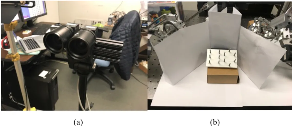
The selection of capture devices is important, because the distortion, raw input images’ format and the resolution of cameras could all affect reconstructions results. For cameras, a pair of Point Grey cameras with the same model is selected because they are able to do hardware synchronization by connecting both cameras to a FireWire board attached to the CPU. Hardware synchronization not only saves effort to conduct software synchronization procedure after capturing but also makes real-time synchronizing rendering possible. For lenses, a pair of similar common range lens with small distortion are selected because they can properly cover the range of target areas of this research. Two cameras are placed almost in parallel and in close distance between each other to fulfill requirements for a stereo vision setup. (Figure 1.1 (a))
Image format will be configured to 16-bits gray-scale pixel format because the algorithm only cares about the density of each pixel. Differences in focal length, zoom level and aperture size between two cameras are minimized manually in order to reduce errors in image pair. The resolution of the output will be configured to 800*600 pixels because it is enough to capture details of the scene and it doesn’t cost too much computational power in reconstruction.
As for target scene setup, a peg board which is usually for laparoscopic surgery training tasks such as peg transfer is placed about 20 centimeters away from the camera to simulate texture-less human cavity. Peg board has no texture and some complexities in shapes, providing an ideal model for human cavities.
(a) (b)
Figure 1.1: (a) is the stereo cameras system setup; (b) is the reconstruction scene setup.
Overview of the software: Implementation of depth acquisition pipeline
As for storing image data, the software mainly uses Mat data type from OpenCV library to store image data. When capturing the data, the software stores image pixel data, image format and time stamp into one pre-defined data type called stream packets as information about one frame of the capture.
Then the frame data is extracted to perform block matching to get depth or disparity map which stores depth information of each pixel on the image. With gained depth or disparity maps, a sequence of algorithms is used to refine the depth information. Finally, to get a more detailed observation of the reconstruction results, a points cloud object will be generated with the depth information and color information of each pixel.
Intrinsic and Extrinsic Calibration
To proceed to reconstruction procedures, intrinsic and extrinsic calibration of both cameras are indispensable, because camera matrixes, transformation matrixes and distortion parameters for both cameras provided by calibration are needed for depth reconstruction. [9]
The calibration process is performed as independent procedures because it is only required when the parameters of cameras are changed. OpenCV calibration functions are used in the system. An efficient and easy-to-operate program is built to automate the calibration process because the usual way is too time-consuming. An interactive interface allows the researchers to select satisfied pairs of frames when playing the captured video. With pairs of frames selected, the program uses the same frame pairs for both intrinsic and extrinsic calibration, avoiding the manual work to select corresponding frames separately for extrinsic and intrinsic calibration. All the operations described above can be performed via keyboard inputs.
Automation of the process shortens the calibration time to less than 5 minutes. For calibration, researcher only needs to start to record and hold a chessboard in front of the camera pair. However, there are requirements to the type of chessboard and the way of holding and moving chessboard.
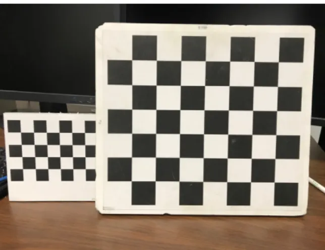
For types of chessboard, the whole chessboard needs to be seen in the image if the chessboard is hold the same distance away from the cameras as the target objects. So, in this scenario, chessboard with 6*7 2cm*2cm square blocks is chosen. During the development phase of the system, the target scenario involves objects with the size of human face which are approximately 70 cm away from the cameras. So, the chessboard with 10*9 4cm*4cm square blocks was chosen. (Figure 1.2)
For the way of holding chessboard, the chessboard needs to be held approximately the same distance away from the camera as the distance between target object and cameras. In this case, the distance should be around 15 cm because both cameras would be set to focus on that distance. If the distance between chessboard and cameras are different from the distance between target objects and cameras, the chessboard would not be in focus, the features of chessboard would be blurred and the calibration results would be inaccurate. For the way of moving the chessboard, in recording for calibration, different angles and positions of the chessboard in the recording should be covered as many as possible. [9]
for multiple sessions of reconstruction with the same camera setup.
Figure 1.2 Left chessboard have the chess block with 2cm in size and right chessboard have the chess block with 4cm in size.
Basic Local Block Matching Algorithm
To acquire depth maps from two synchronized image streams, local block matching algorithm is used. The main procedure of local block matching in stereo reconstruction is that for each block of pixels of the first image, the most similar block of pixels need to be found in the second image. The similarity of two blocks is defined by matching scores calculated from two blocks with particular cost function. The smaller the difference, the more similar the two blocks. After two most similar blocks are found in separate images, the depth information of the block can be calculated with calibration data and pixel positions of the block. [3]
For the above procedure, two approaches can be taken, which are both implemented and analyzed in this section. First approach is rectifying the image pair and comparing the blocks of pixels of first image with only the blocks of pixel of second image whose center pixel is at the same row as the first one. Rectification process is to adjust all pixels of a pair of images so that the pixel coordinates of certain object in two images only have difference in x-axis. So, in a rectified image pair, for each pixel in one image, only pixels with the same x position in the other image can be a candidate correspondence. The differences in x-direction between two corresponding pixel positions are defined as disparity value. The disparity can be transformed into depth via equation: [3]
D = f ∗𝑏 𝑑
where b is length of baseline between two cameras, f is the focal length, d is the disparity value and D is depth from the camera’s aperture. It is obvious to see that, with fixed focal length and baseline length, disparity value is inversely proportional to depth value. For debugging purpose, this approach and standard rectified data from Middlebury stereo dataset is used at the initial stage of the implementation. [3]
multiplication for each pixel. By contrast, the rectification approach first needs to change the pixel coordinates of every pixel based on the movement of cameras from original position to rectified one and generates a new rectified image. Using projection matrix directly saves one stage of loading, calculating and saving pixels’ information. Therefore, the system takes this approach for reconstructing captured image pair from the hardware setup instead of standard dataset. After the most similar block in the second image is found for each pixel in the first image, a depth map can be formed for all found suitable z (depth) values. The procedure described above can be demonstrate by following formula: [11]
𝑝) = 𝐾)[𝑅)|𝑡)][R1|t1]31(K131𝑝1∗ 𝑧)
Where p1 and p2 are pixel coordinates in the first and second image respectively, R1, R2 are rotation matrixes, t1 and t2 are position vectors, K1 and K2 are intrinsic calibration matrixes for the first camera and second camera respectively, z is changing value of depth within pre-defined range. With this formula, different blocks with different pixel coordinate of the center pixel from the second image can be gained by changing z depth value. Another difference in this approach will be that raw disparity values gained will all be integer because the algorithm only takes a block of discrete pixels. By contrast, depth values gained from projection matrix will be float values because transformation and calibration matrixes all involve floating point values. The pixel coordinates gained from a sequence of matrix multiplication could also have floating point value. However, it is impossible to get the density value of the pixel with floating point value coordinates directly. In this implementation, a formula which takes distance from two nearest neighboring pixel as linear ratio multiplied by the density value of the neighboring pixels in both axis is used for getting density of pixels with floating point coordinates. The formula can be illustrated below:
r9 = 1 − 𝑓9; 𝑟? = 1 − 𝑓?
dA = 𝑟?∗ r9∗ 𝑑1 + 𝑟?∗ 1 − 𝑟9 ∗ 𝑑)+ 𝑟9 ∗ 1 − 𝑟? ∗ 𝑑C+ 1 − 𝑟9 ∗ 1 − 𝑟? ∗ 𝑑D
Where (x1+fx, y1+fy) is the pixel coordinate in floating point value, fx and fy are floating point values less than 1, (x1 , y1), (x2 , y1), (x1 , y2), (x2 , y2) are pixel coordinates of four interested neighboring pixels with d1, d2, d3, d4 as density values respectively and df will the result for density of pixel coordinates with floating point value. Here x2 = x1 + 1 and y2 = y + 1. Since pixels in one block all have floating point value coordinates, this formula needs to be applied for every pixel in the block.
(a) (b) (c)
(d) (e) (f)
Figure 1.3 (a) is ground-truth disparity map; (b),(c),(d) are disparity maps with same block size 7 pixels and with different cost functions: SSD, NCC, ZNCC respectively; (d),(e),(f) are disparity maps with with ZNCC cost function but with different block size: 7 pixel, 11 pixel, 15 pixel respectively. (Ground-truth image source [3])
see their influence on the reconstruction results.
The first variable is selection of cost functions to calculate difference between two blocks of pixels. Three cost functions were implemented in the system: Sum of Square Difference (SSD), Normalized Cross Correlation (NCC), Zero-Mean Normalized Cross Correlation (ZNCC). The comparison of performance of different cost function on standard data is shown in Figure 1.3.
With comparison to the ground-truth depth, NCC and ZNCC are usually preferred to SSD because SSD are not robust to some consistent discrepancy between images such as variation of brightness in two images caused by different exposure time of two cameras.
experiment also shows that when block size reaches extremely large value such as 25 pixels, the depth or disparity extraction becomes too smooth to miss some small depth features in the scene. Based on previous comparison, 15 pixels in block size is a suitable value for the standard datasets.
The last variable that was investigated is the iteration times of each blocks in the first image. This variable is strictly considered in approach that uses projection matrix to get the depth map.There is no need for this variable in disparity searching because the step size will be, by default, one pixel in rectified images. Since the matching block can only be in x-axis, finding the matching blocks in the second image will retain row number of the block of in the first image and sweep the blocks in the second image by some number of pixels at either left or right depends on the relative position of the second image to the first one. The iteration number of sweeping the block is closely related to quality of the depth map. The higher the iteration number, the smaller the step size as sweeping of comparison go through a range of depth and the more likely the sweeping will be able to find more precise depth value for each pixel. The step size mentioned above is determined by minimum range, maximum range and iteration times. The way to calculate step size is illustrated by a formula below:
step = ( 1 𝑧HIJ−
1 𝑧HK9)/𝑡
Where step is step size, zmin is minimum range, zmax is maximum range and t is iteration times. With the step size, a new depth value z can be calculated from from one iteration of number of steps started from minimum range zmin. The calculation can be illustrated by the following formula:
z = 1 1
𝑧HIJ− 𝑠 ∗ 𝑠𝑡𝑒𝑝
(0 ≤ 𝑠 ≤ 𝑡)
where s is the number of steps which is iterated from 1 to t and z is the result of depth value which will be used for further calculation in matrix multiplication. Such reverse fashion of calculating depth value is used because it can sweep the range in smaller discrete steps when the depth value is closed to minimum range. In such way, the object nearer to the camera can get more detailed reconstruction.
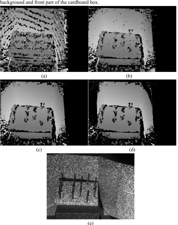
The comparison between depth maps with different iteration number is in Figure 1.4. From the picture (a), (b) and (c), depth map gets finer as the number of step increases, because more iteration steps within the same sweeping range, which means more blocks are compared in the same range, increases the precision in depth values. If the number of steps is too few, the block matching procedure would miss some correct blocks and fail to find the depth value eventually.
background and front part of the cardboard box.
(a) (b)
(c) (d)
(e)
Figure 1.4 (a), (b), (c) and (d) are depth map with the same block size, minimum and maximum range and iteration steps of 20, 40, 100 and 200 respectively. (e) is the raw image for reference.
and distortion eliminating the distinct features of blocks. As the number iteration steps increases, more ambivalent blocks become the candidates for the best matching blocks, thus increasing the possibility to select wrong corresponding block in the image. Large errors are eliminated by the occlusion test, which is described in following sections, resulting in missing depth value. From this experiment, it is not always true that the more iteration steps, the finer the reconstruction results.
Sub-pixel Refinement Algorithm
Since the sweeping of depth in the block matching algorithm is in discrete step from the minimum to the maximum, which means it changes by certain amount of value for each matching loop, the found most similar blocks may not be the actual block with the least matching cost value in the whole range. Some depth values are missed within one discrete step when the depth range is swept. If the size of discrete step is large enough, the strip pattern can be easily seen from the depth or disparity map. (Figure 1.5) As the analysis above, such strip patterns are caused by the absence of intermediary depth values between two discrete ones. To get rid the strip patterns, a sub-pixel refinement algorithm needs be used inside block matching loop.
The idea of the algorithm is to consider either depth or disparity value as x-value and matching score as y-value. The function between depth values and matching scores can be approximated to a quadratic equation. Finding depth/disparity values with the minimum matching scores can be transformed into finding the minimum of quadratic equation. To find three parameters of the quadratic equation, three points on the parabola are needed. Therefore, three points that are taken is the depth value that are found with discrete steps with its matching score and two neighboring depth value different by a discrete step size with their matching score: P1 (d1, s_min), P2(d1 – (step_size)*1, s2), P3(d1+(step_size)*1, s3). (Figure 1.5)
Figure 1.5. Approximate the relationship between depth value and matching score as x-y value in quadratic equation (Image Source: [1])
With these three points, the new minimum depth value could be found, by using the formula below:
a = 𝑦1− y) xC− x) − (yC− y))(x1− x)) 𝑥1)− 𝑥
)) 𝑥C− 𝑥) − (𝑥C)− 𝑥)))(𝑥1 − 𝑥))
b = 𝑦1 − y) xC)− x)) − (yC− y))(x1)− x))) 𝑥1− 𝑥) xC)− x
)
) − (𝑥
C− 𝑥))(x1)− x)))
dHIJ = 𝑥HIYYZ[ = −
2𝑎 𝑏
Where p1(x1, y1), p2(x2, y2), p3(x3, y3) and dmin is the result depth value with minimum matching score.
The comparison between disparity maps with and without sub-pixel refinement algorithm can be seen in Figure 1.6. The disparity map is more smooth and free of strip patterns after refinement.
(a) (b) (c)
Figure 1.6. (a) Strip patterns of disparity maps with 7-pixel block size of ZNCC as cost function without processing of sub-pixel refinement algorithm; (b) Disparity map after sub-pixel refinement algorithm and same parameters as image(a); (c) Ground-truth disparity map. (Ground-truth image source: [3])
There is a small difference between applications of sub-pixel refinement algorithm in disparity map and depth map. For disparity map, two neighboring discrete pixels are taken in the second image. If the center of the best matching block has column number x, then the center pixels of two neighboring blocks will be x-1 and x+1 respectively. For depth map, however, two center pixels’ pixel coordinates of two neighboring blocks differ from the center pixel’s coordinates by one iteration step’s size. In such way, the sub-pixel refinement algorithm cannot override the rough value gained by block matching algorithm but refine the depth value within one iteration step’s size.
Occlusion Test Algorithm
occlusion test algorithm should be applied.
Currently, depth values are searched in one way, from a block of pixels in the one image to the block that has minimum matching cost scores in the second image. Such process can be reversed to get the second version of depth or disparity map. If all the depth values that are found in both versions, they should be match to each other by a small amount of error. Following describes procedures of matching a pixel pair in separate depth maps. For each pixel of the first version depth map, its depth value z and pixel coordinates are used to find a 3D point in the camera coordinates of the first image. Then, it is transformed into a 3D point in the camera coordinate of the second image by plane-to-plane transformation with the camera intrinsic matrix and extrinsic matrix between two cameras. The coordinates of this 3D points should match to the coordinate of 3D points gained by transforming pixels in the second version depth map to the second camera’s coordinates with intrinsic matrix. Since depth values are calculated by approximation, exact matching for every pixel is experimentally impossible. However, the occluded pixels have much higher error than the pixel with correct depth. Hence, a proper threshold will be set for the matching error. Pixels which have higher errors than the threshold in the test are set to 0 for depth value.
Procedures described above can be illustrated by following formula: [11]
C) = [𝑅1|𝑡1][R)|t)]31K ) 31𝑝
)∗ 𝑧)
C1 = K131𝑝 1 ∗ 𝑧1
error = C1− C)
Where C1 and C2 are points in camera coordinate of the first image gained by two versions of depth value z1 and z2 respectively, K1 and K2 are intrinsic matrixes for two cameras respectively, and [R1|t1] and [R2|t2] are transformation matrixes for two cameras respectively. Error value will be the result to compared with threshold value. Currently, this implementation set the threshold value to 0.5 centimeter.
Implemented and tested by the system, the occlusion test algorithm was proved to be effective. (Figure 1.7)
(a) (b) (c)
(a) (b)
(c) (d)
Figure 1.8 picture (a)(b) is the raw image which contains density values and the depth image which contains depth values respectively; picture (c)(d) is two screenshots of the points cloud object generated from the picture (a)(b).
Generating 3D Points Cloud Objects
Sub-pixel algorithm and occlusion test described above intend to eliminate artifacts discovered from the depth map. To present refinements’ effect visually more detailed, more detailed results other than 2D depth maps are needed. To achieve this, points cloud objects need to be generated from the point of view of cameras. Since all the depth values are already inside depth or disparity map, only one step that needs to be done is to get the camera coordinates for each pixel with its z value, its pixel coordinates and intrinsic matrix of the selected camera. Formula below was used in the implementation: [11]
C = K31𝑝 ∗ 𝑧
Where K is intrinsic matrix, p is pixel coordinate, z is depth value and C is camera coordinate of corresponding pixel.
The selection of adding color to the points cloud was also implemented by taking the RGB value or gray-scale value of the pixel and assigning it to the corresponding point inside points cloud. (Figure 1.8)
to form an edge. Then, the edge finds the nearest neighbor point to form a triangle. For each triangle formed, two new edges are formed. For each of these two new edges, two new triangles can be formed by finding other closest neighboring points. If any triangles have edges large than a pre-defined constant threshold, the triangle is recognized as invalid and eliminated because it could connect some distant noise pixels and represent a non-existing surface. The recursive algorithm ends when all points are tested for triangulation.
Regularization Algorithm
After the points cloud object is generated from the depth map, some jagged patterns of the reconstruction become apparent which are failed to be observed from depth or disparity map. The reason for the jagged patterns is that even though sub-pixel refinement algorithm is used, the approximation is a local refinement procedure with only two neighboring depth values considered. Local approximation ignores the overall smoothness of the surface, resulting in inconsistency in depth value over the whole surface that is reconstructed. Such inconsistency becomes the observable jagged pattern in the points cloud object. (Figure 1.7)
Hence, a global regularization over all the depth values is needed to further refine the reconstruction. The idea is to create a cost function in forms of a gigantic matrix which incorporates all depth values. The result of the cost function represents the smoothness of the surfaces reconstruction. The lower the result, the smoother the reconstruction. New depth values for all pixels are values that minimize the result of the function. The idea above is represented by the cost function below: [8]
ε D = 𝛼b 𝐷b− 𝐷b )
b
+ 𝜔be 𝐷b− 𝐷e
b,e ∈h
)
where 𝛼b is a coefficient of quadratic equation gained from sub-pixel calculation, 𝐷b
with slash head is raw depth value of certain pixel, E are the four neighboring pixels of certain pixel and 𝜔be is given by
1/(1 + 𝛽|∇𝐼 𝐷 , 𝐷e |)
where 𝛽 is a constant. The cost function can be transformed into a quadratic form of
(a) (b) (c)
(d) (e)
Figure 1.8. (a) General view of reconstructed 3D object; (b) closer view of points in point cloud which are without regularization; (c) closer view of points in point cloud which are processed by the global regularization algorithm; (d) is the points cloud object without regularization reconstructed from close object; (e) is the same reconstruction result as (d) after processed by regularization algorithm with 15 iterations and beta 0.5.
need to be adjusted to find the most proper ones for reconstruction under specific circumstances. [8][10]
One additional problem for regularization algorithm remains unsolved as it was observed after multiple trials. Regularization algorithm works well for mid-size object in mid-range such as a human face model stands 50 cm away from the cameras. From the reconstruction results, the regularization algorithm failed to work for small size objects in close range which is a 10cm*5cm*3cm peg board sits 20 cm away from the camera. After regularization, the surface of reconstruction appears to be in wave shape, which means the surface is smoothed but not flat as expected. (Figure 1.9)
The hypothesis is that the surface smoothing procedure is overly aggressive. Some small detailed features are smoothed as jagged patterns and originally flat surface are overly smoothed to become wave shape. Several aforementioned sets of variables have been experimented but no effective solution was found. Due to the limited period of conducting more detailed research, this issue will be left for further exploration.
Parallel Computing Feature with CPU
surface features. However, higher resolution images also increase the computational time of block matching algorithm by ratio of squared increase in image resolution. For example, if the original computation complexity is n and resolution of images is increased by k times, then the new computation complexity will be k2*n.
Chapter Two: Structured Light Component
Problem in Primitive Stereo Reconstruction System
After several reconstruction tests of the system, many problems arise. One problem that this chapter tries to address is the failure in reconstructing texture-less objects. To analyze the failure, texture of object needs to be defined. Textures are defined as surface patterns of a 3D object. In a 2D image which includes some objects, textures function as the spatial segmentation of the object from the whole image. For example, what distinguishes a colorful poster on the wall is its texture. However, if the object has surfaces which are mostly monochrome, such as a white wall with only white color on the surface, there will be hardly any distinct surface patterns for such objects. So, in this thesis, objects that have mostly homogeneous surfaces are texture-less objects.
(a) (b)
(c) (d)
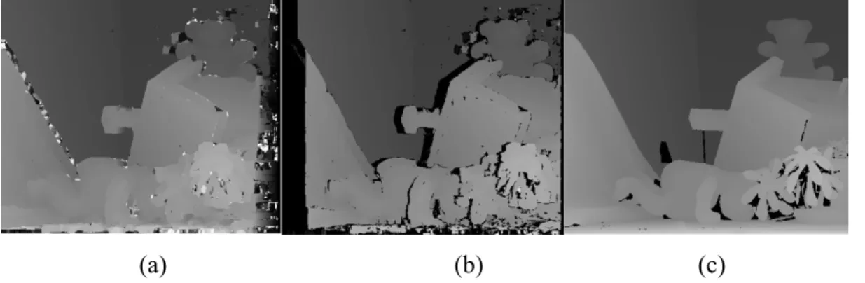
Figure 2.1. (a)(b) are gray-scale image captured by the first camera and corresponding depth image respectively in middle range (60 – 70 cm); (c)(d) are image captured by the first camera and corresponding depth image in close range (15 – 20 cm).
For the laparoscopic surgeries scenario, the target area and organs will be texture-less because they all mostly have the same color, the color of inner human tissues. In the simulated scenario, the target objects will also be texture-less because the peg board’s rectangle body is completely white and its vertical sticks are completely gray.
From the images, such failure in reconstruction is obvious for middle range reconstruction depth map, in which most part of the white wall behind human model failed to get depth detected. (Figure 2.1(b)) By contrast, the human model’s face with distinct facial features and its shirt with different colored square is reconstructed. Similar issue can be found in close range reconstruction depth map, in which the peg board’s white part at the side failed to get its depth detected while the box under the peg board which pasted with color poster gets reconstructed. (Figure 2.1(d))
The primitive stereo reconstruction system uses local block matching algorithm as the basis. In the algorithm, the detection of depth depends on the matching scores of different blocks of pixels. When the algorithms of calculating matching scores of two blocks are closely examined, which are SSD, NCC and ZNCC in the implementation, the calculation of matching scores depends on the discrepancy between texture features of two pixel blocks. Suppose there is a completely white surface of an object is captured in the image. If the block matching algorithm is applied to find the depth of the surface, it will fail because it cannot find a distinct block for a block that is completely contained in the area which captured the surface. Multiple blocks with only white pixels are indistinguishable for cost functions. Therefore, it is impossible to find the correct depth value from multiple blocks with the same matching score. This artifact prevents primitive stereo vision reconstruction system from reconstructing objects with homogeneous surfaces.
There are also some interesting exceptions for texture-less objects. (Figure 2.2) From the images in Figure 2.2, the surface of cardboard is correctly reconstructed even though the cardboard’s surface is, based on visual cues from the gray-scaled image, a brown homogeneous surface, which is expected to fail in reconstruction. However, from the depth map, the brown surface turns out to be well reconstructed. One Possible reason for such exception is that the surface of cardboard is not actually a homogeneous surface but has distinct features which cannot be seen from human eyes. So, a homogeneous surface cannot be determined by human eyes.
(a) (b)
Figure 2.2 (a) shows how the scene looks from the left camera of camera pair. (b) shows the reconstruction result from the picture (a).
One intuitive approach to solve problems in reconstructing texture-less objects is to provide distinct textures to the target objects, so that the block matching algorithm can reconstruct texture-less objects based on projected texture on the surfaces. With a projector, a pre-designed pattern can be projected onto the target objects. Images with distinct patterns on all surfaces should be the same as objects with textures. It is also reasonable to have a projector as a controlled light source because artificial light source will also be needed for lightening up patients’ cavity during the surgeries.
Structured light pattern can also avoid repeated patterns of reconstructed objects which can also cause failures in reconstruction because of the same reason for which texture-less objects fail to get reconstructed.
In general, structured light component functions the same as natural light sources and can also help solve multiple issues which natural light source cannot solve.
Basic Setup of Structured Light Component
There are many possible setups of projector-camera system for choosing. This chapter analyzes two and tests one.
The first general setup would be one camera accompanied by one projector. In this setup, the projector functions similarly to the second camera in a stereo vision system. Therefore, precise extrinsic and intrinsic calibration need to be performed for both the camera and the projector. Once the calibration is done, the patterns that will be projected onto the surface should be encoded to recognized all the surface features on the pattern. The way of encoding patterns will be discussed in the later part of this chapter. [7][13] The second general setup, which was incorporated by the system, is one pair of cameras accompanied by an additional projector. The difference between two setups is that no calibration is required for this additional projector because the projector only functions as light source and pattern generator for the scene. Also, no special encoding is required for the projected patterns. However, the patterns do need careful design to ensure the quality of reconstructions.
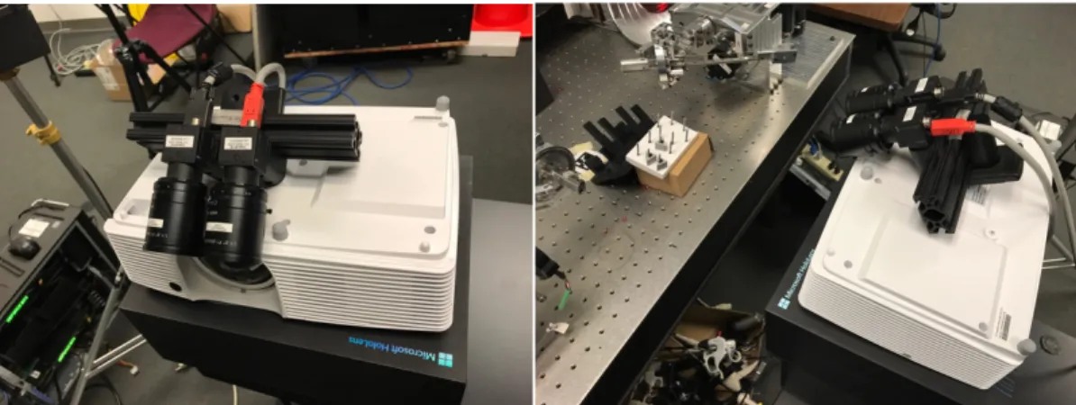
There would also be some requirements for the projector in both setups. The projector, just like cameras, should have the target object in focus so that patterns could be projected onto the surface of the object clearly. Also, light emitted by the projector needs to be bright enough so that the patterns will not be disturbed by the natural light. Therefore, the projector used for this system is a Optoma DLP projector which has enough brightness for the lab environment. (Figure 2.3) However, in the real scenario, demands for the brightness of projectors would not be high because there will be no other light sources in human cavity except for the projector itself.
cameras and projector should be minimized to approximate such perfect position. Currently, the projector and cameras are positioned as the Figure 2.3 have shown.
Figure 2.3. the left image is the relative position between cameras and projector and the right image is overview of the setup and target scene.
Temporal Single Camera and Single Projector System [13]
As mentioned above, the projector functions as the second camera in the system. To get correspondence of the image captured by the camera, either each pixel or each set of pixels needs to be encoded by a unique identifier from others so that it can be identified and reconstructed. This thesis will discuss two ways of using structured light patterns to find depth in the camera-projector system.
The first one is temporal structured light which uses time-multiplexing strategy to encode each pixel of projected space with a sequence of patterns. For temporal structured light, the most commonly used encoding mechanism is binary encoding. Each projected pattern includes two values for each pixel: 0 and 1. They are represented by black pixels and white pixels respectively in the patterns. With a sequence of n such patterns, the maximum number of pixels these patterns can encode is 2n because each pattern can represent one digit of binary values for each pixel and n patterns can represent binary values with n digits. [7]
When a complete sequence of binary encoded patterns is projected onto the surface, camera which stays in the same position takes one image of each projected pattern together with the scene. With such sequence of captured images, each pixel or small block of pixels with projected patterns in the camera image can be identified with the binary values combined from a sequence of binary signals represented by the patterns. So, a pair of corresponding pixel coordinate in camera and in projector can be gained for each such pixel or pixel block. The depth value can be solved via following formula: [9]
𝑝) = 𝐾)[𝑅)|𝑡)][R1|t1]31(K
131𝑝1∗ 𝑧)
Where p1 and p2 are pixel coordinates in the image and the projected pattern respectively, R1, R2 are rotation matrixes, t1 and t2 are position vectors, K1 and K2 are intrinsic calibration matrixes for the camera and the projector respectively, z is the depth value that should be solved.
block matching algorithm because such correspondence matching avoids searching procedures which involves calculating matching scores for each possible blocks in the range step by step. Assume both the time looking for pixel coordinate given a code value and the time conducting matrix calculation above to solve depth value are constant. The computational complexity to find depth correspondence is only O(n) where n represents number of pixels in one image.
The difficulty of such approach lies in synchronizing frames between projector and camera and edge detection of every pixel in order to recognize binary value for all possible pixel in the image. Synchronization between projector and camera is indispensable because for each frame from the camera, a corresponding binary encoding pattern from the sequence is needed for finding the value of a certain digit in encoded values. To achieve synchronization, a special projector which allows frame synchronization from outside source and special hardware such as Firewire used for synchronizing cameras are needed. This will not be discussed in detail because hardware problems are not in the scope of this thesis.
Edge detection means determining the position of edges which divide black areas and white areas. Edge detection is crucial for deciding if the pixel is in white blocks and black blocks within projected patterns. Since the captured camera would have noise pixels, the actual parts of the image with projected pattern will not be completely black or white. So, the easiest way to know if a pixel is projected black or white is to determine where black or white block starts and ends or, in another way to say, the edge between two distinct blocks. The shift between black and white will not be instantaneous because of resolution of the camera and the projector. Hence, one way of detecting edges with sub-pixel accuracy is proposed.
Approximate the density value of pixels near edges as a function with y-value as density value and x-value as either row number or column number of the pixel. Then calculate the derivative of this function and find the zero-crossing of the derivative. The position of the edge with sub-pixel accuracy will be the x-position of the zero-crossing because it represents the pixel which shifts most in density. [7]
One possible drawback for this structured light system is the restriction of hardware and limitation of frame rate. Restriction of hardware is already discussed above which is that the synchronization between camera and projector limits the selection of cameras and projectors. There will also be some decline in the frame rate of a sequence of reconstructions because each reconstruction needs n frames to receive n patterns. If the camera’s frame rate is f, the maximum frame rate of the reconstruction is f/n. If the system is a real-time system, the performance will be negatively influenced by such limitation. [13]
certain amount of pixels or higher resolution for each pattern. [7]
Spatial Single Camera and Single Projector System [13]
The second way of using structured light is spatial. It projects a single special pattern in which a pixel’s coordinate can be uniquely identified by itself and its neighboring patterns. Microsoft Kinect sensor V1 will be a suitable illustration of spatial pattern. Kinect sensor relies on one infrared emitter and one infrared camera to reconstruct depth from the scene. These two have a baseline distance of 75 mm. During reconstruction process, infrared emitter emits a special infrared dot pattern onto the target scene. (Figure 2.4) The infrared camera simultaneously captures the target scene. To conduct correspondence search between the captured image and the stored dot pattern which is projected, the camera needs to filter out other natural light to make sure no other light sources can disturb the window matching procedure. [15]
Correspondence search in Kinect is called Region-growing Random Dot matching algorithm. It is similar to local block matching algorithm by using cost function such as NCC to calculate the matching scores of two blocks of pixels in two images. However, Kinect sensor searches correspondence in random fashion instead of doing block matching starting from the left top corner of the image row by row. It first identifies all dots in the image. Then it starts from a random dot which is defined as an anchor of the region and conducts block matching along the scan-line. If the best matching score is less than pre-defined threshold, the anchor is set as valid, otherwise, invalid. If the anchor is valid, then its neighboring pixels will be added to a queue and block matching will be applied on them around its own neighborhood which is gained by shifting the position of anchor by a certain value. If the best matching score is found to be less than the threshold, then this pixel’s neighboring pixels will also be added to the queue. This recursive procedure ends until the queue is empty. After the best matching block is found, the disparity value can be gained by comparing distance between pixel coordinate of the pixel in the image and pixel coordinate of the pixel in the dot pattern. [2] Then the depth value can be gained via following formula:
D = f ∗𝑏 𝑑
where b is length of baseline, f is the focal length, d is the disparity value and D is depth from the camera’s aperture.
The whole matching procedure ends after all dots in the image either find depth or marked as invalid. This algorithm can help reduce the noisy pixels because it will focus on the area with dots in the image and ignore the areas where have no projected pattern covered. In such way, it could potentially be more computational efficient than the local block matching algorithm. [2]
One improvement to this algorithm is to add sub-pixel refinement algorithm. In this algorithm, no additional refining algorithm is applied. So, the reconstruction results of Kinect sensor have apparent strip patterns. Since it also does block matching by sweeping, the algorithm can utilize the sub-pixel refinement algorithm mentioned in chapter one to get rid of strip patterns.
in the stereo camera system. Similar block matching procedure will be applied to find correspondences between the image and projected pattern instead of the second image in the stereo cameras system.
(a) (b)
Figure 2.4. (a) shows Kinect V1’s dot pattern; (b) shows how the dots positioned on the measured scene (Image Source: (a)[15], (b)[2])
Calibration of projector and camera
For the single camera and single projector structured light system to work, both projector and camera need to be calibrated to get intrinsic and extrinsic parameters. As for intrinsic and extrinsic calibration of camera, chapter one has given detailed description with commonly used OpenCV library’s calibration function. Intrinsic and extrinsic calibration of projector, however, is a little bit more complicated than those of cameras because the projector which projects image onto the surface does not know how patterns look like after being projected from the point of view of projector.
In traditional OpenCV calibration function of the camera model, two matrixes are needed to feed into the function as arguments. The first matrix containing all points with three dimensions is called object points which describes how the pattern should be positioned when the z values of all points on the pattern are the same. Take a chessboard with chess block of size 5 cm for example. The first feature point which is the corner of four white and black blocks at the top left corner can be described as (0,0,0) and then the next point which is at the right side of the first one (5,0,0), then (10,0,0), (10,5,0) and so forth. The second matrix containing points with two dimensions is called image point which should be the pixel coordinates of chessboard corner appeared in the image. The detection of chessboard corners is handled by another special function in the OpenCV library. Also, the points in object points matrix should correspond to the points with the same indices in image points matrix. [9][5]
Each image of the same chessboard with different positions and rotations should have the same object points matrix and different image points matrix. With one set of image points matrixes and one object points matrix, the calibration function will return intrinsic parameters and extrinsic parameters relative to the chessboard by solving following camera model equation: [5]
q = K (R|t)Q
dimension, K is intrinsic matrix, R and t are rotation matrix and translation vector of the camera, Q is the 3D object points.
For projector, image points matrix can be gained directly from projected pattern. The difficulty lies in the how to gain the object points because the 3D position of the feature points will change as distance from the projected surface to the aperture of the projector varies. [5]
One way of using a calibrated camera, a printed chessboard and a projected chessboard image is proposed. For each transformation of chessboard relative to the projector and a calibrated camera, two pictures should be taken by the calibrated camera. One is the image of printed chessboard, the other is the image of projected chessboard pattern on the original chessboard object after the printed chessboard pattern is covered with a flat sheet of paper. (Figure 2.5) The first image can give extrinsic parameters of the camera by solving pinhole camera formula which is mentioned above. The second image can produce object points matrix by using extrinsic parameters from the first image and image points from chessboard corner detecting function from OpenCV library. For projector, image points matrix will not change because the projected image stays the same but object points matrix constantly changes as the transformation of chessboard changes relative to the projector and the camera. After enough sets of object points matrixes are gained, they can be fed into the OpenCV calibration functions to get the intrinsic and extrinsic parameters of the projector. [5]
Figure 2.5 (Image Source: [5])
Camera Pair and Single Projector System
However, all the single camera and single projector systems mentioned above have a common drawback. There will be some degree of interference if multiple structured light systems are set up to capture different angles of the target scene because multiple projected patterns can overlap on the same surface. As edge detector or block matching algorithm sweep this surface, it cannot identify the pixel coordinates of this area in the projected pattern because overlapping area could produce new pattern which is not identical to any of the original patterns.
images, no pre-defined pattern is needed for finding correspondences. Therefore, the calibration of projector and special encoding of projected patterns are not required in this system.
However, the design of projected patterns should still be carefully considered because projected patterns can affect the quality of reconstructions. First, the algorithm of creating patterns should be determined. The patterns in this system are in mosaic fashion. (Figure 2.6) For each block in the image, the pixels in the block all have same density and the block size can be self-defined. To ensure that the blocks in the pattern have visible differences in density from their neighboring blocks, the density range is divided into lower half and higher half. For each pair of adjacent blocks, density of one block is randomly selected from the lower half while density of the other from the higher half. Since one block of pixels in the pattern can be seen as a pixel with larger size than that of original pixel, changing the block size is the same as changing the resolution of the projected pattern. The resolution of generated pattern also needs to be considered. To fully utilize the resolution of the projector, the resolution of projected pattern should be the same as that of the projector which is 1920*1080 pixels in this case.
(a) (b)
Figure 2.6 (a) shows projected pattern which have block size of 1 pixel; (b) have block size of 20 pixels; they all have 1920*1080 in resolution
(a) (b) (c)
(d) (e) (f)
(g) (h) (i)
(j) (k) (l)
Figure 2.7 picture (a), (b), (c), (g), (h) and (i) shows the depth map reconstructed under projected pattern with block size 1, 3, 5, 10, 15 and 20 pixels respectively; picture (d), (e), (f), (j), (k) and (l) shows the corresponding raw image in the same sequence. All the reconstruction is produced with the same stereo matching variables with block size 15 pixels, 60 iteration steps, 20 cm minimum range and 45 cm maximum range.
shrinks.
When the block matching is applied on pixels at the vertical edges of projected blocks, there will be multiple best matching pairs because the projected block is so large that it the same as a small homogeneous surface. It is highly possible that wrong blocks are selected as the best matching ones. Even though the wrong blocks are selected, the wrong blocks are near to the actual correct ones. This explains why the noisy pixels in the strips having no significant errors. Also, if the errors are too large, occlusion test would get rid of those pixels. This explains some missing depth parts in the strips. For other pixels, the blocks contain the edges of more than one projected blocks. So, the blocks can be uniquely identified from their features and correctly reconstructed. This theory explains why depth map is more refined as the projected pattern’s resolution gets higher because more blocks in the image receive distinct features as the resolution gets higher.
From the comparison of picture (g)(h)(i), the depth map is almost the same when projected pattern have block size of 5, 3 and 1 pixels respectively. Some pixels missed their depth values as the resolution gets higher. (Figure 2.7 (i) bottom part) The reason for such phenomenon could be that the resolution of projected pattern is high enough for blocks in camera image to be distinctly recognized. Increasing resolution will not change such fact. However, as the projected pattern’s resolution gets higher and the resolution of camera stays the same, which is 800*600 in this case, it is possible for a projected pixel to be smaller than a pixel of the camera image. In this case, the density of pixels in camera image could be the mixture of density of multiple pixels from projected pattern. The mixture and blurring would eliminate some pixels’ density contrast from their neighboring pixels, creating some small homogeneous surfaces and causing the missing depth values in some pixels.
Motivation for Infrared Structured Light Patterns
There are some disadvantages of using projector to project visible textures onto objects. As the visible pattern is projected onto the object, the pattern could prevent humans from correctly recognizing objects in the original image. For example, a small object with distinct color from the surrounding environment can be made identical to the surroundings by strip or mosaic patterns. (Figure 2.7 (j)) From the image, the whole peg board is covered with visible patterns and the pokes of the peg board is hard to recognized due to the disturbance of visible patterns. If the surface is human tissue with a small thin wound, it will be hard to recognized with the same disturbance.
patterns from the images for reconstruction. While the visible light channel of the camera which filters out infrared light can be used for giving texture to reconstruction results. Such approach is more robust than the previous one in the selection of projection devices. Applications such as Kinect sensor which uses the infrared projected pattern to reconstruct depth have already been discussed in the Spatial Single Camera and Single Projector System section of this chapter. For color textures from the scene, one more color camera can be added to the system with extrinsic and intrinsic calibration. The color of reconstruction results can be gained by, with each pixel in the depth map, conducting a plane-to-plane transformation from the image plane of infrared camera to that of color camera to get RGB values from the colored image. [15]
Another disadvantage of using visible structured light pattern is the disturbance of natural light source. The brightness of surrounding environment could influence the visibility of patterns on objects and the quality of reconstruction significantly. The reason for such influence is that natural light sources which increase the density value of all pixels in the image make the difference between neighboring pixels’ density value blurred.
One solution which have already solved issue is to decrease the aperture size to make the image dimmer so that the difference in density of different blocks can be seen more clearly. Infrared structured light pattern could also solve this issue. The system can simulate Kinect by using infrared camera pairs and infrared projector. Since the IR cameras will filter out other natural light sources, they are robust to disturbance from other light sources.
Chapter Three: Future Work
Photometric Feature
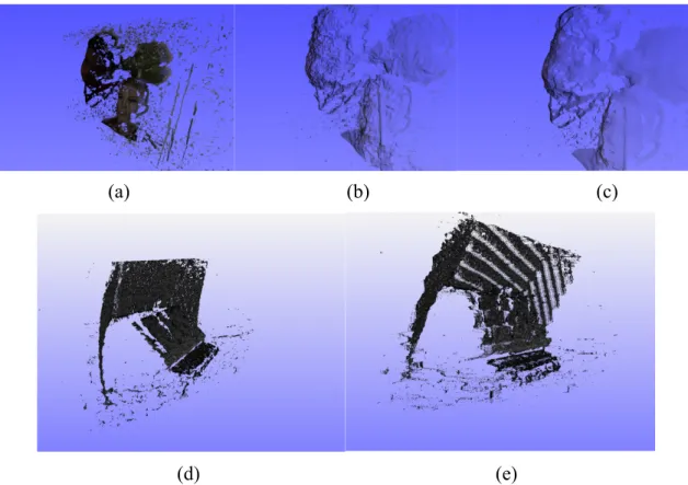
One problem in stereo vision system that the structured light assistance failed to solved is the false reconstruction of specular surfaces such as metal objects or shiny human cavity covered with fluid under the light. Such issue was discovered during the reconstruction tests. Previous setup of peg board was put on a flat metal surgical bench. The reconstruction of such scene has many noise pixels. To confirm that these noise pixels are caused by metal surfaces of surgical bench, the metal surfaces were covered with white sheets which have diffused surfaces. Compare reconstructions of two scenes with the same stereo matching variables, the amount of noise pixels decreases significantly after the surroundings are covered with white sheets. (Figure 3.1)
(a) (b) (c)
(d) (e) (f)
Figure 3.1 (a) and (d) are raw image of scenes with the same projected pattern. (b) and (e) are depth maps without and with cover of white sheet respectively. (c) and (f) are screenshots of 3D points cloud object from similar points view without and with white sheets covering respectively.
reconstruction of the surface which are those noise in the reconstruction results.
Even though the solution to correctly reconstruct specular surfaces is not in the research scope of this thesis, proposed solution from literature review is given because real laparoscopic surgeries will encounter specular surfaces. One common photometric technique is shape from distortion. The basic idea of shape from distortion is to solve the normal map of the surface by observing how the pattern is reflected by the surface. Since the reflectivity of one surface does not change, changing the light rays’ directions leads to different directions of reflection. The shape of the specular surface can be calculated by synthesis analysis of multiple projected patterns from various positions. (Figure 3.2) [16][6]
Figure 3.2 Pipeline of shape from distortion (a) setup projectors to project distinct patterns from various fixed world positions; (b) images are captured for every patterns; (c) The world positions of pixels in the image are determined by analyzing the reflective patterns on the surface; (d) depth and normal information are extracted from (c); (e) surface map can be reconstructed. (Image Source: [6])
Real-time System with GPU Programming
For the reconstruction system to be used in real scenario, the stereo reconstruction system needs to be a real-time system because all the operations based on the reconstruction need to be conducted in live. Currently, each frame of reconstruction with 15 pixels in block size and 200 steps in iteration takes approximately 3.5 minutes with parallel computing features of CPU applied. Since the duration is already decreased by a factor of 8 because of 8 cores in the CPU, the original computation time is around 28 minutes. The frame resolution is 800*600 in pixels. Suppose there could be a thread assigned for each pixel in the image, 28 minutes could be reduced by a factor of 800*600. Ideally, the computation time is expected to reduce to approximately 0.003 second, which is short enough for reconstructing from a frame rate of 30 frames per second camera. Besides this, multiple refinement algorithms could be added to improve reconstruction quality.
GPU programming would be an ideal approach to realize such proposition. GPU is able to assign a block which is similar to a thread to each pixel in the image and conduct block matching on the second image simultaneously. This is expected to be done once the stereo matching algorithm is more refined and more robust.
Ideal Stereo Setup in Real Scenario
to function in small confined human cavity with small insertion holes. To fit the system’s hardware into such restricted area, cameras pair with tiny scan-line and thin lens and projector with small body are needed. Based on the search online, stereo laparoscope can be selected as camera pair like Figure 3.3. To have the additional structured light component, one artificial light source can be modified to project special infrared patterns onto the target scene while the other used for illumination. One more colored camera can be added to the laparoscope to provide color texture to the reconstruction results.
Conclusion
3D reconstruction is a broadly useful topic as it can be utilized in many fields, such as self-driving vehicles, human face identification and medical imaging. This thesis takes a deep look at how stereo vision reconstruction works and also adds structured light assistance to increase system’s effectiveness.
References
[1]. C. McCormick. Stereo Vision Tutorial. Jan 2014
http://mccormickml.com/2014/01/10/stereo-vision-tutorial-part-i/
[2]. Dereck Hoiem. How the Kinect Works from Computational Photography. Dec 2011.
https://courses.engr.illinois.edu/cs498dh/fa2011/lectures/Lecture%2025%20-%20How %20the%20Kinect%20Works%20-%20CP%20Fall%202011.pdf
[3]. D. Scharstein and R. Szeliski. A taxonomy and evaluation of dense two-frame stereo correspondence algorithms. IJCV, 47(1/2/3):7-42, April-June 2002.
[4]. Henry Fuchs , Mark A. Livingston , Ramesh Raskar , D’nardo Colucci , Kurtis Keller , Andrei State , Jessica R. Crawford , Paul Rademacher , Samuel H. Drake , and Anthony A. Meyer, MD. Augmented Reality Visualization for Laparoscopic Surgery. 1998.
Medical Image Computing and Computer-Assisted Intervention — MICCAI’98, Volume 1496
[5]. I.Din, H.Anwar, I.Syed, H.Zafar and L.Hasan. Projector Calibration for Pattern Systems. Feb 2014. Journal of Applied Research and Technology, Volume 12, Issue 1. https://www.sciencedirect.com/science/article/pii/S1665642314716086#!
[6]. Ivo Ihrke, Kiriakos N. Kutulakos, Hendrik P. A. Lensch, Marcus Magnor and Wolfgang Heidrich. Transparent and Specular Object Reconstruction. 2010. Computer Graphics Forum, Volume 29, NO. 8.
https://www.cs.toronto.edu/~kyros/pubs/10.cgf.transparent.pdf
[7]. Joaquim Salvi, Jordi Pages, Joan Batlle. Pattern codification strategies in structured light systems. Oct 2013
[8]. M. Zollh𝑜fer and M. NieBner. Real-time Non-rigid Reconstruction using an
RGB-D Camera. ACM SIGGRAPH 2014. July 2014
[9]. OpenCV. Camera Calibration and 3D Reconstruction.
https://docs.opencv.org/2.4/modules/calib3d/doc/camera_calibration_and_3d_reconstru ction.html
[10]. P. Komarek. Minimizing Quadratic Forms. 2014. http://komarix.org/ac/papers/thesis/thesis_html/node9.html
[11]. R. Szeliski. Computer Vision: Algorithms and Applications. Sep 2010. http://szeliski.org/Book/
[12]. Sylvain Bernhardt, Stephane A. Nicolau, Luc Soler, Christophe Doignon. The status of augmented reality in laparoscopic surgery as of 2016. Jan 2017.
[13]. Sean Ryan Fanello, Christoph Rhemann,Vladimir Tankovich Adarsh Kowdle, Sergio Orts Escolano, David Kim and Shahram Izadi. HyperDepth: Learning Depth from Structured Light Without Matching. Jun 2016. CVPR, 2016 IEEE Conference. http://ieeexplore.ieee.org/document/7780956/
[14]. TradeKorean.com. Dr. Camscope 3D Laparoscopy System. Retrieved from: http://www.tradekorea.com/product/detail/P294949/Dr--Camscope-3D-Laparoscopy-System.html
Infrared and Depth Images. Dec 2016. IEEE Transaction on Cybernetics, Volume 46, NO. 12. http://ieeexplore.ieee.org/stamp/stamp.jsp?arnumber=7328728
[16]. Yiwei Zhang, Graham M. Gibson, Rebecca Hay, Richard W. Bowman, Miles J. Padgett and Matthew P. Edgar. A fast 3D reconstruction system with a low-cost camera accessory. Apr 2015. https://www.nature.com/articles/srep10909
![Figure 1.5. Approximate the relationship between depth value and matching score as x- x-y value in quadratic equation (Image Source: [1])](https://thumb-us.123doks.com/thumbv2/123dok_us/8330270.2209606/11.892.280.607.731.983/figure-approximate-relationship-matching-quadratic-equation-image-source.webp)

![Figure 2.5 (Image Source: [5]) Camera Pair and Single Projector System](https://thumb-us.123doks.com/thumbv2/123dok_us/8330270.2209606/25.892.286.610.604.738/figure-image-source-camera-pair-single-projector-system.webp)
