Pitch Control of DFIG Wind Turbine Based on Fuzzy Logic Controller
T.Anil Kumar, Ch.V.V.MangalakshmiPG scholar, Dept of EEE, Assistant professor , department of EEE Pragati Engineering College
JNTUK, Surampalem, A. P.
Abstract: With improvement in variable speed system control and design of wind power system, the energy capture of these systems also rising. For enhance the efficiency and performance of wind energy conversion system(WECS),In this paper come up with Pitch angle control of a Doubly FED Induction Generator(DFIG) based wind power system with the objective of maintain constant power with variable wind speed by using fuzzy logic controller. This paper presents principal conversion of wind energy, wind turbine linearization and dynamic modeling are derived. The fuzzy logic controller is employed for change blade angle of wind turbine and constant power can be achieve. The block diagram of proposed pitch control which consists of pitch controller, actuator model and turbine linearized modeled by using Matlab/Simulink software.
Keywords: FLC, PC, DFIG, WECS.
I .INTRODUCTION
In renewable energy sector wind Energy has been the major source in country. Generally At variable speed and fix speed wind turbine operates for generate power. The wind genetic phenomenon from many causes; atmospheric pressure, temperature difference and rotation force of earth. These reasons produce the wind speed and power [1]. Now days, utilization of wind energy is increased due to clean, friendly for environment, free and reusable resource. Wind turbines convert wind energy into electrical energy. By using mechanical equipment converts kinetic energy form wind to mechanical energy for utilization [2]. However, there are many unsolved problems in wind energy. The conventional controller as well as newly enhanced advanced controllers for horizontal, Variable– speed wind turbines proposed [2]. Most of wind plant construct with Double fed induction Generators (DFIG).DFIG used in variable speed wind turbine for generating constant frequency and voltage in wind power system [3]. DFIGs are
rugged and simple construction and good efficiency under different operating conditions. Induction generators are require low maintenance and less cost. Optimization of variable wind energy can be solved by using pitch control with fuzzy logic controller.
II.THEWIND ENERGY SYSTEMS
The wind energy conversion system four major equipment with a generator, wind turbine, gearbox, interconnection apparatus and control system. Normally wind turbine classified into two different types namely horizontal and vertical axis type. The wind turbine consists of three or two blades. The wind generator operates with either up wind or down-wind. Major wind turbines manufactures have opted gears between high speed three phase generators and low wind turbines. Fig.1 shows that Different pitch angle has been analyzed for wind turbines.
Fig.1 Characteristics of wind turbine
AC/DC/AC converters. The DFIG generator minimizes stress on wind turbine while low wind speeds. Elimination of capacitor is another advantage DFIG. Also DFIG has ability to absorb or generator reactive power.
II.I WIND TURBINE SYSTEM MODEL
Fig.2 Block diagram of the WTGS
Fig.2 shows that wind power generation, first it involves the converts the wind energy into mechanical torque by using wind turbine to gear box than it convents mechanical torque into electrical power by using induction generator. Due to variation in wind power y due to the input variable like wind speed, Pitch angle and tip ratio because force designers to consider close loop control system as show in fig.2 order to get an effective and constant wind power. For this variable wind speed conditions turbine model is play key role in power generation.[] and [] described about wind energy generation by using variable and fixed wind turbine, that analysis shows that variable speed wind turbine gives better response than the fixed wind speed turbine due to the sudden changes in wind speed variations. Due to reason in this paper considers the variable speed wind turbine coupled to a DFIG.
II.II DYNAMIC MODELING OF THE WIND TURBINE
The wind turbine is designed by dimensional less curves of power coefficient (C) as function of blade pitch angle (ß) and tip speed ratio (λ). In order to
utilize wind energy optimum λ value should maintained .Therefore the CP value will reach maximum value. The ratio between the angular rotor speed of wind turbine to the linear wind speed at the tip of the blades. It shows as below
W r
V
R
(1)Where R is the wind turbine rotor radius, wind speed is vw.mechanical angular rotor speed wtof the wind
turbine. The wind turbine generated power can be derive from below equation
3 2
)
,
(
2
1
W P
m
R
C
V
p
(2)Where (
) is the air density, and (A) is the swept area by the blades, andi 4 . 18 14
. 2
i
P( , ) 0.73[151 0.58 0.002 13.2]e
C
(3)
Where λIis
1
03
.
0
02
.
0
1
1
3
i (4)Also torque generated from the wind turbine can show in below
V
ARC
T
m
T2
1
(5)Where CTcan define as
PT
C
C
(6)II. III. DOUBLY-FED INDUCTION GENERATOR SYSTEM
Fig 3 Block Diagram of DFIG based wind turbine
The stator windings transmit electrical power generated by the wind turbine driven double fed Induction Generator. DFIG consists of AC/DC/AC converts call rotor side converter (RSC) and stator side converter (SSC). The GSC converter maintains constant DC-link voltage and the RSC controls reactive active power of induction machine. The GSC is not used to inject reactive power in grid and RSC injects reactive power independently in to the rotor. But, During the low voltage and steady state conditions, Reactive power will generate by GSC.In dfig rotor can capable for power flow bidirectional. Power will flow from the rotor to grid when ωr>ωs,
power will absorbs the energy from grid when
ωr<ωs, .Rotor amplitude and frequency of grid adjust by using power electronics converters. The mechanical power and the stator electric power output are computed as follows: The stator electrical power and mechanical power are define below
r m M
T
P
(7)s em S
T
P
(8)equation for lossless mechanical energy is
em m
T
T
dt
r
d
j
.
(9)
In study state at fixed speed for a lossless generator :
em m
T
T
(10)r s m
P
P
P
(11)Follows
s em r m s m
r
P
P
T
T
P
(12)s s m
s s r s m
sP
sT
T
)
*
(
Where S is defined as the slip of the generator
s r s
S
)
(
(13)Where, Pmech is the extracted mechanical power. Ps is the power from the stator to the grid. Ptotal is the total generated electrical power. J is the combined rotor and wind turbine inertia coefficient. Pr is the power from the rotor to the grid. ωs is the
synchronous speed.ωr is the rotor rotational speed.
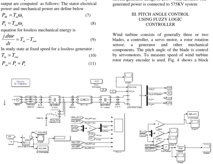
The Matlab/Simulink model for proposed system is show in fig.5. It consists 10MW wind turbine generator design of 2MW wind turbines. The generated power is connected to 575KV system
III. PITCH ANGLE CONTROL USING FUZZY LOGIC
CONTROLLER
Wind turbine consists of generally three or two blades, a controller, a servo motor, a rotor rotation sensor, a generator and other mechanical components. The pitch angle of the blade is control by servomotors. To measure speed of wind turbine rotor rotary encoder is used. Fig. 4 shows a block
diagram of wind turbine pitch angle control using Fuzzy Logic controller (FLC) for less rated wind speed. By controls the blade pitch angle to wind turbine speed is maximizes. From Fig. 6 rotor speed in rpm from encoder is compared with reference speed of rotor. The Fuzzy logic controller considers rotor speed error and change in error as inputs.
Fig 6 shows the fuzzy logic control system, consists of Fuzification, Rule based control, Decision making, Defuzification. For this FLC system input are consider as error in rotor speed and change in error in rotor speed. In Fuzification process the inputs are converted into seven linguistic variables show in Fig 7 & 8 .For decision making a sueno method is used with 49 rules
Fig.5 Fuzzy Logic control Systems
Fig.6 pitch angle controller
Fig.7 rotor speed error
Fig.8 change in error in rotor speed
Fig.9 fuzzy rules
Fig 10 Surface view of fuzzy rules
Surface view of fuzzy logic rules as show in fig.10. a centroid method is used for defuzzification.
IV. SIMULATION RESULTS
Simulation Design of Pitch control DFIG System as show in Fig 4. In this system Five wind turbine , For each turbine 2MW power will Generates with 575 V voltage and generated voltage step up transmitted for 30kmП- line at 25KV. Finally it will connect grid at 125KV.Fig 12 shows generator voltages, current, generator real, reactive powers, DC link voltages and rotor speed, grid voltages, currents at different wind speeds. Fig. 11 show different Wind Speed. For graphs take with respective time vs per unit values of respective quantity.
Fig : 11 Wind Speed of DFIG OUTPUT
Fig.12 Generator voltage, Currents, real, reactive powers, Dc link voltage, Rotor speed, Grid voltages
and Currents
V.CONCLUSION
This paper proposes implementation of Fuzzy logic control in pitch angle control for DFIG based wind energy conversion. Fuzzy logic control is design with sugeno 49 rules, it effectively controls the pitch angle to get better response in power generation and voltage generation maintained constant value. The Simulation and modeling proposed model is designed in Matlab/Simulink software. The simulation results show that fuzzy controller effectively regulates pitch angle of wind turbine.
VI .REFERENCES
[1] Liuchen Chang “Wind Energy Conversion Systems”, IEEE Canadian Review -spring / Printemps, pp. 12- 16, 2010.
[2] Abdel Aitouche and Elkhatib Kamal,“Intelligent Control of Wind Energy Conversion Systems”,
ISBN: 978-953- 307-467-2, InTech, 2011.
[3] Q. Wang and L. Chang, “An intelligent maximum power extraction algorithm for inverter-based variable speed wind turbine systems,” IEEE
Trans. Power Electron., vol. 19, no. 5, pp. 1242-1249, Sept. 2004.
[4] Boik, S.2003.Grid Requirements challenges for wind Turbines. Billund: Fourth International workshop on Large–scale Integration of wind power and Transmission Networks for Offshore Wind frame.
[5] Slootweg, J.G., de Haan, S.W.H., Polinder, H., and Kling, W.L. 2003. General model for representing variable speed wind turbines in power system dynamics simulations. IEEE Transactions on Power Systems, Vol.18, No.1, pp.144- 151.
[6] Iov, F., Hansen, A. D., Sørensen, P., and Blaabjerg, F. 2004. Wind Turbine Blockset in Matlab/Simulink. Denmark: Aalborg University. [7] Pena, R., Clare, J.C., and Asher, G.M. 1996. Doubly fed induction generator using back-to-back PWM converters and its application to variable-speed wind- energy generation. IEEE Proc.-Electr. Power Appl., Vol. 143, No. 3.
[8] Mugica, M.S., Urkiola, A. M., Vidal, M. R., and Redondo, R. R. 2004. Comparison of Dynamic Space Models for Wind Turbine Grid Integration Studies. Portugal.
[9] Akdag, S. A., and Guler, O. 2010. Comparison of Wind Turbine Power Cuve Models. Sousse, Tunisia: International Renewable Energy Congress. [10] Bharanikumar, R., Yazhini, A. C., and Kumar, A. N.2010. Modling and Simulation of Wind Turbine Driven Permanent Magnet Generator with New MPPT Algorithm. Asian Power Electronics Journal, vol. 4,No:2.
[11] Melicio, R., Mendes, V. M. F., and Catalao, J. P. S. 2009.Computer Simulation of Wind Power System : Power Electronics and Transient Stability Analysis. Kyoto, Japan: International Conference on Power System Transent(IPST2009).