from Windows Vista to Windows CE
Tutorial :
Getting Started
with Movicon 11
M O V I C O N 1 1
T U T O R I A L
Movicon™ is a trademark of Progea, related to the HMI/SCADA platform entirely developed and produced by Progea. © 2008 All Rights reserved.
No part of this document or of the program may be reproduced or transmitted in any form without the express written permission of Progea.
Information in this document is subject to change without notice and is not binding in any way for the company producing it.
Table Of Contents
1. GETTING STARTED WITH MOVICON ... 4
2. PROJECTS ... 5
H
OW TO CREATE AND STRUCTURE A PROJECT... 5
C
REATING AN
EWP
ROJECT... 7
W
ORKSPACE... 10
P
ROJECTP
ROPERTIES... 11
P
ROJECTS
TRUCTURE... 12
3. TAGS ...13
H
OW TO CREATET
AGS... 13
H
OW TOC
OMMUNICATE WITHD
RIVERS... 15
C
ONFIGURING THED
RIVER... 17
A
SSIGNINGP
HYSICALA
DDRESSES TOT
AGS... 20
I
MPORTINGT
AGS DIRECTLY FROMPLC ... 22
4. SCREENS ...24
H
OW TO CREATE AS
CREEN... 24
S
CREEN AT THE PROJECT STARTUP... 26
G
RAPHICE
DITING... 27
O
BJECTL
IBRARIES... 28
S
YMBOLSL
IBRARY... 30
C
REATING AC
OMPOSEDS
YMBOL... 31
5. DYNAMIC ANIMATION ...34
H
OWT
O CREATED
YNAMICC
OLORS... 34
O
THER EXAMPLES OFD
YNAMICA
NIMATIONS... 37
H
OW TO EXECUTE COMMANDS FROMO
BJECTS... 40
A
SSIGNINGT
AG'
S VALUE FROMO
BJECTS... 41
A
SSIGNING EXECUTING COMMANDS TOO
BJECTS... 43
S
TARTR
UNTIME... 44
6. ALARMS MANAGEMENT ...45
H
OW TOM
ANAGEA
LARMS... 45
I
NSERTINGA
LARMO
BJECTS... 45
D
ISPLAYINGA
LARMS... 50
D
ISPLAYINGA
LARMH
ISTORY... 53
1.
Getting Started with Movicon
Welcome to the Movicon tutorial. This tutorial is aimed at giving you a quick guided demonstration of the main Movicon Scada/HMI platform techniques used. At the end of this tutorial you will have learnt the most essential techniques for using Movicon base functionalities.
Before going ahead with this tutorial you should first install the software by using the setup procedures.
All the information in this document is based on the assumption that: 1. Windows is the operating system being used
2. The user knows how to use the Windows’ techniques
3. The user has sufficient knowledge on automation systems, on variable and PLC concepts
For further information on each argument, please consult the Online Guide or the User’s Manual
2.
Projects
How to create and structure a project
Starting up Movicon with the option command line, the program will start in Programming mode (Developer). The last project being used is usually opened. The workspace will display empty upon the first execution. The workspace uses the modern disappearing window techniques and therefore just simply point the mouse on the Tab you require to make it appear in the workspace. To keep the window displayed in the workspace use the relevant commands as indicated below:Note: to display your working windows just point them with the mouse and use the dock command to keep them visible.
Movicon Workspace with hidden windows
Movicon workspace with window kept displayed
Tip: you can close the property window and double click on it to make it re-appear.
Creating a New Project
To create a new project, use the ‘New’ command from the File menu (Ctrl+N).
A Wizard will appear to guide you in creating the new project:
First of all you need to select the type of platform on which the project must be run. In this way the functions which are not supported by the selected platform will not be available in programming mode (the selection can be changed later). Confirming this operation will display the configuration window:
In the window (as shown above), you will need to enter the desired name of the project in editing phase.
The other settings are not to be used for the time being but can be checked out in the manual if wished.
Click on the Next button to open the ‘Users’ settings.
The security settings can be defined in this window. We will skip this part for the time being and go on with Next button to access the Driver settings.
The drivers you wish to include in the project can be selected from this window. We will also skip this part and leave it for later. We will not set anything at this stage. Now click on Next button to reach the Screens Settings.
Here you can indicate whether or not to create screens in the project. You can also indicate whether to create each one with a Title, and a contents navigation bar with scroll page buttons on the bottom border.
The default setting can be left alone or adapted to your requirements which can always be changed later.
Going still ahead with the wizard other windows will be shown for the configuration of the possible historical, alarms etc..
On the last window, Alarm Settings, when confirming these operations with Finish button, the wizard will proceed creating the project according to the settings carried out.
The Wizard will create the project’s structure by pre-setting all the basic configurations in automatic.
Workspace
By default, the Movicon workspace appear as shown below:
The Movicon Workspace, windows, toolbars, properties can be full customized.
Project Properties
Each Movicon project has properties, which are used to set all the project’s configuration functions.
To display the project’s properties, click on the project name, at the beginning of its tree structure, or select the name and activate the Properties Window with the right mouse key.
The Project’s properties permit you to setup the general characteristics of the project itself, among which are:
1. Eventual encrypted file protection
2. Selecting project’s destination Operating System 3. Working Folder paths
4. Setting Startup behaviour (runtime execution- includes the 'Enable Renaming Manger' for automatically renaming variables linked to objects)
5. Operating system access security 6. Heap Memory settings for CE 7. Historical Log settings 8. Spooler print settings
For further details on all the properties please refer to the Programmer’s Manual.
Project Structure
The Movicon projects are built from a set of files XML format. Each project resource is saved in a XML file in the relating project’s folder and in the subfolder of the relating resource.
Unless specified otherwise, the projects are saved in the "Documents\Movicon Projects" default folder.
The files, being ‘open’ thanks to the XML, can be encrypted and compressed in the project by means of using the project’s properties. The structure of the files respects the structure the resources provided in the Movicon project window.
Let’s go over the structure of the project files in detail, using the Windows Resource Explorer.
3.
Tags
How to create Tags
To introduce a new variable (Tag) into the project you need to: 1. Select the Real-Time Database resource from the project window
2. Select the “Add a new Variable” command from the Command Pane found at the bottom of the project window. You can also use the analog command by using the right mouse key.
A new variable will be created in the project with default name and properties. The Properties Window, if hidden, is displayed by double-clicking on the new variable (if can be further displayed by using the relevant command from the ‘View’ menu).
You now need to assign the properties deemed necessary, especially the General properties, through the ’Properties Window’.
In our case we shall keep the default settings, with the PLC address to be assigned later. However we shall briefly go over the main properties for you:
Let’s go over which are the fundamental properties of each Tag: Name: permits you to assign the name desired for the variable. Type: permits you to specify the data type (bit, byte, word, etc.)
Area: permits you to indicate whether an explicit memory area is to be used for the supervisor. When leaving the area as ‘Not Shared’, the supervisor will decide if the tag must be considered for the licence. The tag will be counted for the licence only if it’s exchanged with the field through the driver, OPC, etc..
Dynamic Address: permits you to set the physical address to connect to the Tag to. The Tags Explorer can be used to specify the connection by means of an I/O Driver, OPC or Networking.
•
All the other properties allow you to go and specify the Tag’s behaviour, in the project, in detail. We, therefore, advise you to refer to the Programmer’s Manual for further details.How to Communicate with Drivers
New communication drivers (I/O Drivers) can be inserted into the project at any time. In order to do this you need to:
1. Select the Real-Time Database Resource from the project window
2. Select the ‘Add a new Comm.Driver’ command from the Command Pane found at the bottom of the project window. You can also use the analog command by using the right mouse key.
3. A window will appear through which you must choose the driver you need from the list of drivers available.
4. Each driver is subdivided into product categories. By clicking on one product will get you the drivers and the relative communication protocols available.
•
We will check the Siemens S7 MPI “PC Adapter” protocol for our example.When confirming the operation the driver will be inserted into the project and added to the list of drivers in the project window.
We can now proceed with necessary configurations through the properties window:
First of all you must proceed with the driver settings configurations from the General properties group.
Go to the ‘Settings’ item where you will find an activation button for accessing the communication settings window.
Configuring the Driver
In this example we have chosen to use the Siemens S7-MPI PC Adapter driver as an example. The techniques used are the same for all the other drivers accept a few protocol specifications. The first thing to do is sort out the configurations of the driver’s General Characteristics.
1. Usually the default settings are left as they are accept for certain specifications required by the device being used. As an example lets suppose we have a standard PLC with a standard MPI connection for which we will keep the General default settings.
2. After the general settings, select the ‘Stations’ window needed for the communication station settings which we will create for the driver.
3. Use the “Add” button to add the necessary communication station to the driver in order for it to communicate.
4. When entering the new Station, its relating settings window will display through which we will configure the communication details of our station for which we will only concentrate on the fundamental properties.
Station Name: Assign a name to the station. In our case we will put PLC1 (but any other name is acceptable).
Port: Assign the serial port number being used. In our case we will use the COM1 serial port, for which we will leave the value left at 1.
Baudrate, Byte Size, Parity, Stop Bit: Assign the parameters of the communication port. In our case we will keep the Default settings. Station ID: this is the last property on the list whose setting is based on the ID address set in the PLC.
All the other station properties permit you to further configure the communication modalities. For instance, the TAPI functions can be used for communicating via modem or the Bridging functions used for communicating via the modem on the PC, to use the same communication port for the PLC’s remote maintenance (eg. Teleservice). To get further information on these features please consult the Programmer’s Manual. However, we will limit ourselves in using just the base functions relating to device communication for the time being.
When confirming the settings, the communication station will be inserted in the communication driver.
Other stations for communicating with other devices on different COM ports can also be inserted with the same MPI protocol.
When arriving at this point the driver should have been inserted and the device already connected and ready for communicating. To verify whether all is in order and working correctly we shall run a test by using the “Test Cable/Comm.” button. In this way Movicon will be able to verify whether communication with PLC device has been set up correctly and the cables are correct. Any errors found should then be resolved to ensure that communication works correctly.
Assigning Physical Addresses to Tags
After having inserted at least one station, we will look at how physical addresses are assigned to Tags.1. Select the Tag previously inserted into the project (or create a new one)
2. Double-click on it to open the Properties Window.
3. Select the ‘Dynamic’ property from the ‘General’ group to open the Tag Browser window.
4. Select the Tab relating to the communication driver from the Browser window.
5. Double-click on the PC Adapter previously inserted to open a window to assign the physical address.
6. Select the driver station with which you wish communicate with (in our example we have only entered the station named PLC1), then specify the device’s physical address in the "Device Address" to which the variable is to be connected.
7. In our example, we shall connect the Word type variable called VAR00001 to the PLC’s DB1 data block’s word DW0.
Note: You can also enter the syntax of the physical address In the Tag' s `Dynamic' property directly:
[DRV]PC Adapter.Sta=PLC1|Addr=DB1.DBW0
With the Tag property set, Movicon will establish communication with the device for reading-writing data from the PLC on the corresponding variable during project runtime.
Importing Tags directly from PLC
The Movicon drivers offer an extremely useful feature when the database of ready-made PLC variables is being used:
The 'Import-Update device database’ command, from the Command Pane, is made available when selecting the driver from the Movicon project window. This same command can be obtained and used by clicking the right mouse key.
When activating this command you will be request to select the file (keeping the CTRL key or SHIFT key pressed down) corresponding to the PLC database. As we are using Siemens S7 we need to select the .SDF or AWL file by means of the file selection window:
When selecting the file with the PLC database, the Movicon Import Device variables window will open to allow you to select all or part of the variables contained in the PLC database.
1. Creating the Tags in the Movicon project keeping the same name and type taken from the PLC database
2. Assigning the relative physical address to each Tag
By using this useful function you can get the Movicon project’s Variables DB created and completed with the device’s physical addresses assigned automatically in just a few seconds.
Each Tag’s ‘Dynamic’ property will be shown associated with the following syntax (which can be changed as pleased):
4.
Screens
How to create a Screen
To create a graphic interface you need to used the project’s Screen resource. 1. Select the Resources Folder from the Project window’s tree structure.
2. Select the ‘Add new screen in the project’ command from the Command Pane at the bottom of the project window. You can also use the analog command by using the right mouse key.
3. The new screen will be created in the project and displayed with its default settings in the workspace.
4. You can change the screens default properties through the Properties Window. This window is accessed by double-clicking on the screen itself or by using the same command from the View menu.
5. We will only deal with the screen’s background color properties. Please refer to the Programmer’s Manual for details on the other properties.
6. Select the ‘Back Color’ property from the ‘Background’ property group and assign white as the screen’s background color.
7. Repeat this operation to introduce another screen into the project. By doing this we can setup an example to be used in the ‘change page’ lesson up ahead.
Screen at the project startup
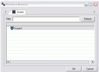
To get the screen to open automatically at the start of a project Runtime you need to specify the screen in the project’s Execution properties.
1. Double-click on the project name at the beginning of the project’s tree structure to display the its properties, or select the name and activate the Properties Window with the right mouse key.
3. We will select ‘Screen 1’ to use in our example (or you can select another one if you prefer). Then confirm with OK.
The specified screen will be the one to open and display automatically at the project startup.
Graphic Editing
We will now re-open ‘Screen1’ to examine the basic graphic editing concepts.
1. Double-click on the ‘Screen1’ resource, found in the Screens folder in the project window, to open the screen.
2. Use the drawings tools by taking them from the Toolbox positioned on the workspace’s right border.
3. Select the ‘Basic Shapes’ from the Toolbox and then select the drawing to be used graphically on the screen.
4. After having selected the chosen drawing, double-click on the insertion point on the screen and drag the drawing until you reach the size desired.
5. Repeat these operations to create the drawing you want on screen.
6. These graphic elements, once on the screen, can be given general, style and animation properties by using the Properties Window as described below.
Object Libraries
In addition to the Basic shapes provided in the Toolbox you can also access other graphic object categories. These categories contain vectorial drawings with style and animation properties similar to those of the basic shapes but already predisposed with execution functions for which they have been designed for.
until you reach the size desired.
After having inserted the your chose objects, you can then proceed with assigning their properties by using the Properties Window. Each object will have, apart from the general properties, also style and animation properties, which are common to all objects, and the execution properties specified for each single object.
Symbols Library
Movicon provides a vast variety of graphic symbols in libraries which have been pre-built purposely to meet all the graphical representation requirements in automation.
These symbol libraries can either be accessed through the ‘Symbol Libraries’ window, displayed on the border on the right hand side of the workspace, or by using the analog command from the ‘View’ menu.
Each symbol from each category can be inserted on screen by simply using the Drag&Drop techniques and re-sizing it as desired by dragging its borders just like any other graphic object.
The symbols can be configured in their properties just like any other drawing object, by using the Properties Window.
Insert a ‘Rectangle’ object into the screen from the ‘Basic Shapes’ ToolBox and a ‘Tank’ symbol from the Symbol Library.
Creating a Composed Symbol
All the drawing elements (Drawings, Symbols, Objects) can be grouped together in Symbols and then added to the Symbol Library.
Now let’s proceed with inserting a few drawing elements which we will then associate to a graphic symbol.
By following the procedure described above, insert a Rectangle and two Ellipses from the Basic Shapes ToolBox to form the shape shown below:
Select all three elements with the mouse by clicking in the area and dragging the selection.
The figure below shows how the drawing should look like with the reference object highlighted for any eventual align commands.
With the right mouse key, in the workspace, select the Symbol – Group command to group all three drawings together to make one symbol.
The symbol can now be added to the Movicon Templates library by using the right mouse key on Symbol -> Add to Library.
Any animations or codes associated to the symbol will also be kept in the library.
The composed symbols can be inspected in the project’s tree structure. The objects and the composed symbols are displayed in structures under the screen they belong to.
When using this technique we suggest you assign a name to each symbol or drawing so that they can be identified straight away.
5.
Dynamic Animation
We will now look at the editing techniques used, which entail the association of Tags, for creating dynamic animations.
How To create Dynamic Colors
In our example we have chosen to assign the animation properties to color the drawing’s background in function with the VAR00001 tag previously introduced.
1. Activate the screen where the graphic symbols were inserted as described above. 2. Select the rectangle shape representing a tube.
3. Double-click or use the other techniques to display the Properties Window.
4. Select the Animation group from the Properties Window and then the Back Color item.
The window contains a series of standard default thresholds. Use the relative commands on the side to delete, add of edit them.
Use the relative settings window, shown below, to add or edit the animation characteristics:
By using this window you can set the threshold values and the animation colors, as well as other properties which are explained in the Programmer’s Manual.
Confirm the settings with OK.
When you Run the project, changing the real-time value of Tag VAR00001, you will see the rectangle shape change color.
Attention: the “Variable for Threshold Color” in this threshold settings window consents to making the activation threshold dynamic. This variable, however, MUST NOT be used in the 'Background color' property, otherwise the color animation will not work correctly by showing only the same color without changing.
TIP: Variables can be associated to objects by directly dragging them from the RealTimeDB resource and dropping them on the objects on screen.
When you select a variable from the variable list and drag and drop it on an object in the screen, a window will display allowing you to select which animations to associate to that variable.
Other examples of Dynamic Animations
We will now insert some animations requiring Word type tags, which can be inserted into the project as described above in chapter 4.Let’s assume that two tags, VAR0001 and VAR00002, both in Word are available in our example project.
We will demonstrate another example of dynamic animation for on screen symbol movement: Composed Movement.
1. Open the screen and select the Symbol, created previously with the Rectangle and Ellipse drawings grouped together, then activate the Properties Window.
2. Select the ‘Animations’ group and then Composed Movement. This animation sets the graphic symbol to move on the screen along a trajectory line graphically drawn out with the mouse in proportion to the tag values associated.
3. Check the ‘Enable’ box.
4. Associate the VAR00002 tag previously inserted
5. Confirm with .
6. Close the property window and activate the mouse’s right key commands from the selected symbol. Select the ‘Edit Composed Movement’ item.
7. Drag the symbol’s shape to the end point, i.e. to the right hand side of the tank.
8. To insert the intermediate points of the path, double-click with the mouse on the line and drag it to the intermediate point desired and continue like this until the trajectory line is complete.
10. Select the Scaling box from the Animations properties group to activate the relating settings window.
11. Associate the VAR00002 tag previously inserted.
12. Enter the 50-100 values as scale Percentage, so that the symbol remains visible at 50% of its scale as minimum value.
When you select a variable from the variable list and drag and drop it on an object in the screen, a window will display allowing you to select which animations to associate to that variable.
How to execute commands from
Objects
Execution commands can be assigned to objects in the screen’s user interface, in function with their characteristics.
We will follow up the chapter reported above regarding graphic animation to complete the argument by explaining the techniques used for assigning execution commands to object. In our case we shall use a ‘Button’ object and a ‘Gauge’ object, which are needed to produce the animation which we configured previously.
1. Activate the screen where the graphic symbols, described above, are inserted.
2. Take a ‘Gauge’ from the ToolBox’s "Sliders-Gauges-Meters" category and insert it in the screen.
3. Take a ‘Green Button’ from the ToolBox’s ‘Buttons-Lights-Switches’ category and insert it in the screen.
Assigning Tag's value from Objects
Example Using Button Objects
Let’s proceed with configuring the button which we will use for acting on the variable used for managing the rectangle’s (tube) color animation.
1. Double-click or use the other technique to display the inserted Green Button’s Properties.
2. Select the Execution group from the properties window and then the 'ON-OFF' Mechanic Style. Select the VAR00001 tag previously inserted. By using this characteristic the button will toggle the Tag, by setting it with the ‘0’ and ‘1’ values. The tag can also be interacted on by using the command selection as we will show you up ahead.
3. Confirm with .
Example Using Gauge Objects
Now we shall configure the gauge which we use to interact on the tag to manage the created symbol’s animated movement.
1. Double click or use the other technique to display the inserted gauge’s Properties Window.
2. Select the Variable group from the properties window and then select the Gauge-Slider Variable item. Select the VAR0002 tag previously inserted. In this way the gauge will interact directly on the VAR00002 tag. The gauge object is totally configurable, by using the numerous properties provided. It is only necessary to do the configuration as indicated for our example. The other properties can be referred to in the Programmer’s manual.
3. Confirm with
TIP: you can also drag the Tag from the project RealTimeDB resource directly to the object on the screen, to simply assign the variable.
Objects
Different types of commands can be assigned to any command object (Buttons, Menu, Accelerators) and command lists can also be created. The commands can be activated by selecting the "Command Type" on the Execution Properties as "Execute Command", then defining the command type by selection the "Command on Release" or Command on Pressed.
The button’s execution properties are:
When activating the ‘Commands’ selection from the Execution properties you can edit the command list to be associated to the object by using the ‘Add New Command’ button in the Command List window.
The ‘Add New Command’ button opens the settings window of the operating commands to be assigned to the object.
Each configured command will be added to the Command List which the object will execute.
There are commands in Tags (Set, Reset, Toggle, Strobe, Increase, Decrease, Virtual Keyboard...) or on Screen windows (with the various opening modalities).
Please refer the manual for further details on all the command operations which can be assigned to objects.
Start Runtime
At this point, with the objects configured we can run the project to verify its Runtime behaviour.
1. Press the button or use the Start Project command from the File menu (or ALT+F12).
2. Movicon will ask you to save the project. Save the project using the classic Windows techniques.
3. After having saved the project on file, it will be executed in run mode where you can operate the objects to see if they work.
6.
Alarms Management
How to Manage Alarms
In this brief lesson we will quickly see how to activate, display and record alarms in Movicon projects.
We shall continue with our example from where we left off with a few Tags and a pair of screens already predisposed in our project.
Note: The alarms are objects from the project. Each alarm has their own General properties where they are assigned names and associated to tags in cases when not used as templates. Alarms used as templates will be dealt with further on.
Each alarm is built with at least one threshold, whose value and condition determine the activation of the alarm with an associated text.
Inserting Alarm Objects
1. Select the ‘Alarm List’ Resource from the project window which in turn will show the relative commands in the command Pane at the bottom.
2. Use the “Add a new Alarm” command from the Command Pane or with the right mouse key. A new alarm object will be created in the project and can be renamed as pleased.
Activate the alarm object’s properties window to assign the desired name, i.e. ALL001, then the Tag from the project by selecting it from those inserted in the project’s Real-Time DB. In our example, the object’s properties are those indicated in the figure below:
Important: if the ‘Quality Good Only’ is left checked the alarm will be activated only when the RealTime DB assigns the tag with a certain value. For instance, in cases where a Tag connected to a driver or in network, becomes disconnected the value turns to ‘uncertain’ and therefore the alarm will not appear. If in doubt, uncheck this option for a test run.
3. After having entered the Alarm object, you can enter at least one activation threshold. Therefore, select the alarm from the project Window and use the ‘Add a new Alarm Threshold’ from the Commands Pane or use the right mouse key.
6. Go to the ‘General’ properties group to assign the ‘Title’ being the text which will be associated to the alarm. The title can be typed directly in the property box or, as a good rule, can reside in the project’s ‘String Table’ and there may be subject to language change.
Note: when using the string table, you need to select the project name from the project resource window and use the ‘Edit String Table’ command from the Command Pane (or using the command made available for use with a right mouse click). Then insert the columns (each column is a text language) and then proceed with inserting the texts which will then be made available all over the project
7. We then have to assign the threshold value in the ‘Value’ box in the ‘Execution’ property group. You can also use a ‘dynamic’ threshold value, where the alarm activation value derives from the contents of another tag. Leave the default activation >= (more than or equal to).
8. The Style and Notification Event properties are of no interest to us for the time being and therefore we will leave those for default.
•
The alarm is historically logged in the file for default and can be traced or reset as well as other characteristics to be referred to in the Programmer’s Manual.The alarm and its activation threshold are now configured. You need to consider that each alarm may have different activation thresholds and if the associated variable is not bit type, but Word type for instance, the alarm is consider to be analog type.
This procedure permits one alarm to be created, with different threshold if need be, for each variable. However, there is another way that allows you to set alarms as "Templates". In order to do this you need to set the alarm as described above, but without specifying the name of the associated variable.
This will make the alarm generic and associated to more than one variable at the same time. If you set more than one variable the List Variables, they can be selected at the same time by pressing the SHIFT or CTRL key.
Once you have selected the variables, you can associate an alarm using the "Associate an alarm" command from the command pane at the bottom or using the right mouse key to get to it.
This command allows user to select the alarm from the previously defined alarm list. Note: It is always best to differentiate the type of alarm you intend to use, therefore when that alarm is used as template with multiple variable associations, you should make sure that the alarm has not been set with a variable in its "Alarm Variable" property.
using the CTRL key technique and call the "Associate an Alarm" command with the right mouse key.
We shall go ahead and choose the ALL002 alarm. We will then see listed the single alarms associated to the two variables. In this case the alarms will behave exactly in the same way as the ALL001 alarm does, simply knowing that the VAR00002 and VAR00003 variables have identical alarm thresholds, even though logged individually for each variable.
The alarm and its activation threshold (each alarm can have a number of activation thresholds) have now been configured.
Displaying Alarms
The active alarms, setup in the project’s Alarm List resource, can be displayed in purpose-made object viewers which can be inserted on the screen.
We need the use of a screen. In our example project we have setup two screens, ‘Screen1’ and ‘Screen2’ where Screen1 has already been used for the graphic examples. Therefore we are left with Screen2 for this example.
1. Double-click on ‘Screen2’, in the Screens folder from the project Window, to open it in edit mode.
2. Activate the Toolbox and take out an ‘Alarm Window’ object from the ‘Advanced Shapes’ category.
3. Click on a point on the screen’s top left, then drag the selection to insert the ‘Alarms Window’ object in the size desired.
4. Double-click to activate the ‘Alarm Window’ object property. The Style property permits you to fully configure the Alarm Viewer object. The Background property permits you to assign the background colour desired for the alarm’s window. The Font property permits you to choose its characteristics as desired. The numerous properties, described in the Programmer’s Manual, permit you to manage the viewing of alarms according to any applied necessities. In our case, for simplicity, we will leave all the default settings as
ey. th
You can modify, add or take away the columns describing the alarms in the Alarms Viewer by using the appropriate tools, which are displayed with the “Shift + Double-click’ in the same window.
Displaying Alarm History
All the alarms are historically logged for default. The recording modalities and the Historical Log archives management can be customized through the Historical Log properties which is accessed by selecting the project name from the tree structure and then using the properties Window.
To display the historical data of the alarms, you need to proceed as described above for the Alarms Viewers.
Apart from the Alarm Viewers you will also find the Historical Log Viewer in the ToolBox. Carry out the same procedures for inserting the Historical Log as described above for the Alarms Viewer.
Keep in mind that the Historical Log window displays system messages for default only and not alarm messages. In order to display alarm messages in our project we will have to set the Log Window's 'Filter Event Type' property to the "All" or "Alarm Messages" value.
All we have to now is verify what we have done. For this we need the following function in the project, considering all that has been realized up to this point:
1. A command for alarm simulation on the alarms page. 2. The change page commands.
Create a Simulation
We shall find room in the Alarms screen window to insert a command object which will interact on the VAR00001 tag associated to the alarms.
1. Open ‘Screen2’ from the project window. Arrange the viewer objects so that the is enough space left for inserting the other objects (i.e. on the bottom border).
2. Insert a ‘selector’ object from the Toolbox and position it on the bottom border. Activate its properties and assigned the VAR00001 tag in the Execution properties.
The selector object will interact on the VAR00001 tag, which we have already assigned to the Alarm object.
The same can be done with the remaining VAR00002 and VAR00003. Therefore we shall insert another two selectors and assign one with the VAR00002 variable and the other with the VAR00003 variable.
3. Insert another new ‘button’ object, again from the Toolbox, as before. Position it on the bottom border at the side of the selector. Activate its properties and assign the opening of ‘Screen1’ in the Execution properties. This button will then permit us to execute a page change to return back to the first page.
used to dispose it on another screen after which its properties can be modified.
Executing Runtime
We now have the necessary items arranged in our example project to test run it:
•
Screen1: graphic simulation screen, with command and graphic animation objects. The appropriate button is used for accessing Screen2.•
Screen2: Alarms simulation screen, with the alarms activation and viewer objects. At this point, we are all set for executing a test run of the project to verify its behaviour during Runtime.1. press the button or use the Start Project command from the File menu (or ALT+F12).
2. Movicon will ask you to execute a project save. Execute the save according to the usual Windows’ techniques.
3. After having saved the project file, it will be put into run mode letting you try out the objects to see if they work.
4. To return to Programming mode use the ALT+F12 keys or the button from the bar.
Note: (you can customize a system menu by inserting all the commands desired, including the ones for shutting down Movicon or Windows from the project in Runtime mode). Please refer to the Programming manual for further details.
In order to generate and delete alarms using the three selectors switches, you can get the alarm's history from Alarm Window as well. You can also analyse the alarm's history displayed in the Alarm Window from when it occurred using the "Get History (G)" command.
If we select an alarm occurrence and click on the "Get Hisotry (G)" command, a '+' symbol will appear at the side of the alarm in the window. This symbol is used for expanding the occurred alarm's history.
You can also check alarm occurrences in the Historical Log window and any other following operations carried out to them.
M O V I C O N 1 1
Movicon™ is a trademark of Progea, related to the HMI/SCADA platform entirely developed and produced by Progea. © 2008 All Rights reserved.
No part of this document or of the program may be reproduced or transmitted in any form without the express written permission of Progea.
Information in this document is subject to change without notice and is not binding in any way for the company producing it.