An Infrastructure for Supporting Spatial Data Integration
*L.L. Miller and Sarah Nusser
Iowa State University Ames, IA 50011
* - Funded in part by a digital government grant from the National Science Foundation, Bureau of Census, US Department of Agriculture, Bureau of Labor Statistics, US Geological Survey
Abstract
The amount of digital data is growing at a rapid rate. In addition to the increase in volume, the number of sites making information available is also increasing. Spatial data is a growing part of the problem. The amount of spatial data that is being collected each year is staggering. As with other types of data, many requests require data from more than one source. The focus of this presentation is to provide integrated access to such data. A model of the infrastructure is presented and the current prototype of the model is briefly discussed.
1. Introduction
Government agencies at all levels actively collect and analyze data. Many agencies also depend on the usage of data in the field. As the amount and quality of geospatial data increases, a number of agencies are actively looking at ways of incorporating and/or collecting geospatial data in their field operations.
A significant number of the field activities use mobile devices to collect data. There is a great deal of variability in these activities. For example, sample surveys are conducted using highly structured protocols, disaster damage reporting involves unpredictable conditions and the need to rapidly collect ad hoc observations and crime scene documentation requires both structured and adaptive approaches. While geospatial data is important to most of these applications, little geospatial data is currently incorporated into any of them. Most importantly, the vast amount of geospatial data that exists in federal and state databases cannot be accessed from these field applications.
An important issue in spatial applications is the need for providing the data needed in the form it is needed. This aspect of the problem may range from locating the appropriate data source(s) to integrating the retrieved data in a form that can be used by the requesting application. Mediation [6,8] has been developed as a means of providing the tools to integrate heterogeneous data sources. Spatial mediation has been studied as a means of making use of these techniques to integrate spatial data. The San Diego Supercomputer Center (SDSC) has been very active in the development of spatial mediators [1,2,12]. Ram et. al [5] have looked at spatial integration based on semantic data networks when use of the data can be predetermined. To improve the use of geospatial data in the field, we present an infrastructure design for connecting field applications to government agency databases. Our approach differs in that it focuses more on generating requests when the form of the request is unknown beforehand.
After an overview of our object view approach in Section 2, we look at our infrastructure model in Section 3. A brief description of the model components is given in Section 4. Some implementation details and a brief discussion of our current prototype are examined in Section 5. Finally, we present some concluding remarks in Section 6.
2. Object Views
The basic unit in our infrastructure is an object view system. The view system is based on an extensible object model (EOM). The view object type is defined as being an extension of the object model (EOM). The use of views in this model is an extension of the work on the Zeus View Mechanism given in [10,11,12]. Two levels of views have proved useful for manipulating data within the proposed infrastructure.
i. Local Interface views
The individual data sources are expected to have local control. The local interface is a view type object that is used by the local data administrator to provide a mechanism to make the local data accessible to the integrated environment. The local interface allows distribution transparency and representation transparency, while hiding or converting (mapping) some of the data from the data source. The local interface belongs to the local data source. It interacts directly with the data source and passes the result to the data wrapper which controls communication with the infrastructure. Many agencies already have programs (systems) that provide such representations of their data.
ii. Global views
Global views are either user defined views or system generated views and can interact with other global views or local interface views (again through the wrapper for the local data source). A sample view is shown in Figure 2.1.
Views can either be implemented in SOAP, the client/server model (CORBA) or as mobile agents. To this point in our project we have implemented use of object views in all three of these communication environments.
3. Model
The infrastructure model can be visualized as a graph Ι= (Ν,Ε), where Ν is the set of nodes ∈ { u=user, m=mediator, c=computation server, t=tool, d=data source, a=administration} and Ε is the set of directed edges used to connect the nodes. The nodes are the individual components in the model and the edges are the communication links between the components. One important note is that from the infrastructure perspective, each node is a wrapper. For example, in the case of a user node, the infrastructure sees a user wrapper (denoted as a field wrapper) as opposed to either the user or a user application program. Wrappers for each node type are fixed to allow for automatic generation of the wrapper during the registration process.
The general graph model given above provides the basis of a very rich combination of interactions. Since it is unlikely that most environments will be willing to allow all possible interactions, we use the term design to imply an infrastructure with restricted access between nodes. For example, Figure 3.1 shows the “graph” of a design that has one user, one mediator, one tool, one computation server, and three data sources as nodes and only supports directed edges of the types (u,m), (m,c), (c,t), (t,c), (c,u), (c,d), and (d,c). Two comments should be noted about the way that we represent design graphs. First, in general we ignore the administration node in the graph, since it does not play a direct role in the flow of requests and data. Second, to increase the readability of the design graphs, we use a pictorial representation of the node types.
The data flow in Figure 3.1 can be described as follows. A user creates a request and the request string is delivered to the spatial mediator. The spatial mediator uses the request string and its available metadata to choose the appropriate data sources, generate the individual data source requests, generate an integration script and an object view. The computation server receives the object view from the mediator and uses it to create a set of object views that it uses to interact with the data sources. The computation server integrates the data from the data sources and returns the required object(s) to the user.
In the next section we look some of the issues surrounding the node types.
4. Model Components (node types)
The node types were briefly considered in the previous section. Here we look at the functionality that is required and what choices are available to system designers. To this point, we have envisioned the administration, spatial
Global_view: C1: Public: map: raster_image; image: raster_image; rivers: vector_data; world_file: vector; … Derivation Section: create map as
get image from L1 where center=coordinates raster_vector_fusion
get rivers from L2 where center=coordinates; Methods:
raster_vector_fusion: …; End_C1;
tool computation server spatial mediator user
Figure 3.1. An infrastructure design with one user. data sources
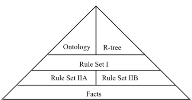
Figure 4.1. Illustration of spatial mediator components. Rule Set I
Facts R-tree
Rule Set IIA Rule Set IIB Ontology
mediator, and computation server nodes as being system resources. The remaining node types are considered producer/consumer components and as such are registered through an administration node for use within the environment.
4.1 administration
The registration process has two primary functions. First, it must get sufficient information to be able to generate the wrapper for the node type. Second, the registration process must collect the necessary metadata for the spatial mediator. Note that metadata must be collected on users and tools, as well as data sources.
4.2 spatial mediator
A spatial mediator has the task of locating data by either a symbolic term or a location. The block structure of our view of the spatial mediator is shown in Figure 4.1. For symbolic terms(like city names), we use an ontology-like approach based on our earlier work[7,8] to locate data sources that contain the term. For either point or bounding box location data, the R-tree is used to locate potential data sources containing the required location. Rule Set I is used with the data source metadata to determine the best data source(s) to use in the integration script sent to the computation server. The rule set is used to rank the matching data sources by how well that they address the requirements of the request. Rule Set IIA is used in combination with all of the relevant metadata available (note, this could include metadata on the user, the tools available, and the data sources chosen) to create the integration script. The integration script is of the form Oα(s1,s2), where Oα is a tool name (e.g., vector_raster_fusion) for a tool that is
either available in the computation server, in a registered tool node, or a object view method. The si are strings that incorporate the location of the data source, the return attribute declaration and the query string needed to request the data from the data source. For the object view shown in Figure 2.1, we would generate the integration script for the agent environment
raster_vector_fusion(“(get image where center=coordinates):(raster_image image, vector world_file):(L1,IP address of L1 wrapper)”,”(get rivers where center = coordinates):(vector_data rivers, vector world_file):(L2,IP address of L2 wrapper)”)
The spatial mediator creates an object view, where the public attributes are the data expected by the user, a variable for the number of return agents used and the integration script. The mediator wrapper passes the resulting object view to the computation server. Our work on spatial mediation differs from the work such as the work on spatial mediation being done at SDSC [1,2,13] in that we focus on generation of the data request.
4.3 computation server
The computation server consists of two primary components. The first component is an object-oriented data warehouse [3]. The data warehouse provides a set of tools for processing and integrating spatial data. The warehouse also serves as an active cache to help improve performance of user requests. The second component manages the user requests by processing the mediator scripts. It is responsible for parsing the integration script created by the spatial mediator, using the information found in the si values to generate object views for the individual data sources, communicate the object views to the data sources. Once the data has been returned, it uses the integration script operations (tools) to guide the integration, and return the results to the user.
4.4 data source
The local interface view (LIV) [11] is designed to export data from the data source into the infrastructure environment. It is used to communicate the query to the data source and package the query result in the object form expected by the infrastructure. The number and type of LIVs is a local decision dependent on how the local information manager wants to share the available data.
4.5 tools
We see a similar structure for tools as we used with data sources. The tool interface converts the incoming data to the format expected by the tool and converts the results to the object format expected by the wrapper.
4.6 user
User access to the infrastructure can take one of several formats. The two obvious ones are via some type of user interface (e.g., gui or a web page) or through an application program setup to communicate with the field wrapper. Most of the work described in the prototype discussion (Section 5) is based on the use of application programs running on pda’s in a field data collection setting [4]. In the next section we briefly overview our current prototype.
5. Prototype
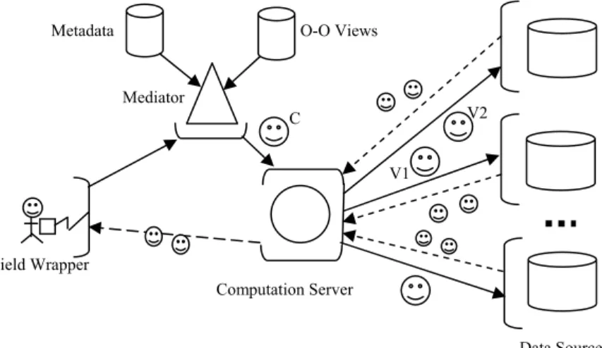
We have implemented a preliminary version of the components described in the previous section. The focus of our implementation has been field data collection [4]. The application programs running on an IPAQ use spatial data that has been received from the data sources through the infrastructure design shown in Figure 5.1.
Our current prototype allows the data source and tool contributors the choice of SOAP, CORBA, or mobile agents (VOYAGER) to set up the communication required to implement the directed edges in the design graph. In addition to supporting communication between nodes, the three approaches correspond to our object views. For SOAP, we pass the data as JAVA objects. The CORBA interface corresponds directly to an object format. The object is the basis of the agent environment which matches our concept of the object view. We use the term view agent to mean a mobile agent that implements an object view.
Our current implementation includes application programs on an IPAQ that interact with a field wrapper (user wrapper) to create the user node described in our model. The field wrapper is currently implemented on a laptop. The connection between the IPAQ and the field wrapper laptop is wireless. We have created a testbed using data from the Alexandria Digital Library at UC-SB, USDA data sets on the Ames, Iowa area, and we hope to develop a Census data set in the future.
We use a scenario to illustrate the functionality of the infrastructure using the view agent approach as the method of communication. The user’s request is formatted by the field wrapper, passed to the mediator wrapper converted by the mediator into an integration script and the script is used as the basis of the object view. To save time and resources, the mediator attempts to choose an existing view agent to process the request. If none exists, a new view agent is
Computation Server
Figure 5.1. Example of current prototype.
V1
V2 Metadata O-O Views
Mediator
Data Sources Field Wrapper
constructed. The resulting view agent is launched with the integration script and sent to the computation server. The computation server uses the data source information in the integration script (i.e., the si) to create the object views that are sent to the data source wrappers. Return agents are launched from the data wrappers to the computation server with the required data. The original view agent is returned to the computation server with information about the number of return agents sent. The arrival of this view at the computation server wrapper allows the computation server wrapper to test to determine whether the data transfer has been successful.
The upper portion of Figure 5.1 illustrates the scenario. The requested data is defined by the global view defined by the view agent sent from the mediator. Note, that the function raster_vector_fusion must be available in the infrastructure (either through a tool node, a computation server tool, or a view method) in order to create the layered map image. The view agent (C) generated by the view C1 (Figure 2.1) is sent to the computation server, since it needs a tool to integrate the two data sets. Once the agent arrives at the computation server, it in turn spawns view agents (V1 and V2 in the example) that take the data requests to the individual data sources represented by the local interfaces L1 and L2. There the spawned view agents can communicate the request to L1 and L2 via the data source wrappers. Note that the local interface views are seen as a set of static programs that are owned by the local data source administrators.
The return agents required to move the result are spawned and the requested data are returned to the computation server. The computation server in turn executes the raster_vector_fusion method and creates the return result for the user. The final result is returned to the field wrapper either by the view agent C1 or a set of return agents that are spawned depending on the size of the results. The field wrapper then passes the data to the user in the field. Similar examples can be set up for SOAP and CORBA. Our prototype can use any combination of the three environments depending only on the method chosen by the particular data sources/tools used in the query.
6. Conclusion
An infrastructure model has been presented for integrating spatial data. The model is based on a spatial mediator that takes metadata on the information needs of the user, data sources and tools available, as well as device characteristics (in field settings) into consideration when processing the user’s request. A prototype of the infrastructure has been developed that brings data to the field setting from the Alexandria Digital Library and/or the USDA data sets that make up our current testbed.
7. References
[1] Gupta, A., R. Marciano, I. Zaslavsky, and C. Baru, 1999. Integrating GIS and imagery through XML-based information mediation. In P. Agouris and A. Stefanidis (Eds). Integrated Spatial Databases: Digital Images and GIS, Lecture Notes in Computer Science. Vol. 1737.
[2] Gupta, A., I. Zaslavsky, and R. Marciano, 2000. Generating query evaluation plans within a spatial mediation framework. Proceedings of the 9th International Symposium on Spatial Data Handling.
[3] L.L. Miller, Ying Lu, Yeping Zhou, A.R. Hurson. 2000. A Data Warehouse Based on Materializing Object-Oriented Views. International Conference on Computers and Their Applications. New Orleans, LA. pp. 68-71.
[4]Nusser, S. M., L. L. Miller, K. Clarke, and M. F. Goodchild. (2003). Geospatial Information Technologies for Mobile Field Data Collection. Communications of the ACM. Special issue on digital government. Vol. 46. No. 1. Pages 45-46.
[5] Sudha Ram, Jinsoo Park, George Ball. 1999. Semantic-Model Support for Geographic Information Systems. IEEE Computer 32(5). pp. 74-81
[6] Subrahmanian,V. S, Sibel Adali, Anne Brink, Ross Emery, James J. Lu, Adil Rajput, Timothy J. Rogers, Robert Ross, and Charles Ward. HERMES: heterogeneous reasoning and mediator system,
www.cs.umd.edu/projects/hermes/publications/abstracts/hermes.html.
[7] Tsai, Hsine-Jen, L.L. Miller, Jian Xu, and Sa Lin. (2001). Using Ontologies to Integrate Domain Specific Data Sources. ISCA 3rd International Conference on Information Reuse and Integration. Las Vegas, NV. Pages 62-67.
[8] Lin, Sa, L.L. Miller, Hsine-Jen Tsai and Jian Xu. (2001). Integrating a Heterogeneous Distributed Data Environment with a Database Specific Ontology. ISCA 2001 Parallel and Distributed Systems Conference. Dallas, Texas. Pages 430-435.
[9] Wiederhold, G. and M. Genesereth (1997). The conceptual basis for mediation services. IEEE Expert, 12(5):38-47.
[10] Yen, C. H., L. L. Miller, A. Sirjani and J. Tenner (1998). Extending the object-relational interface to support an extensible view system for multidatabase integration and interoperation. International Journal of Computer Systems Science and Engineering, 13(4):227-240.
[11] Yen, C. H. and L. L. Miller (1995). An extensible view system for multidatabase integration and interoperation.
Integrated Computer-Aided Engineering, 2(2):97-123.
[12] Yen, C. H., L. L. Miller and S. H. Pakzad (1994). The design and implementation of the zeus view system.
Hawaiian International Conference on Systems Science, pp. 206-215.
[13] Zaslavsky, I., R. Marciano, A. Gupta, and C. Baru, 2000. XML-Based Spatial Data Mediation Infrastructure for Global Interoperability. Fourth Global Spatial Data Infrastructure Conference.