Wireless Security System
Installation & Programming
Instructions
PRINTER’S INSTRUCTIONS:
INSTR,INSTL,2GIG-CP2-345E,V1.9 - LINEAR P/N: 233497 A - INK: BLACK - MATERIAL: 20 LB. MEAD BOND WITH 80 LB. WHITE COATED COVER - SIZE: 8.500” X 11.000” - SCALE: 1-1 - FOLDING: ALBUM FOLD - BINDING: SADDLE-STITCH - FINISH: 3-HOLE STD. DRILL
2GIG-CNTRL2
(2GIG-CP2)
STANDARD FOR ALARM LOCATION
Smoke detectors used with this system should be installed in accordance with Chapter 2 of the National Fire Alarm Code, ANSI/NFPA 72 (National Fire Protection Association , Batterymarch Park, Quincy, MA 02269) which reads as follows:
2-1.1.1 Smoke alarms shall be installed outside of each separate sleeping area in the immediate vicinity of the bedrooms and on each additional story of the family living unit including basements and excluding crawl spaces and unfi nished attics. In new construction, a smoke alarm shall be installed in each sleeping room.
2-1.1.2 For family living units with one or more split levels (i.e., adjacent levels with less than one full story separation between levels), a smoke alarm required by 2-1.1.1 shall suffi ce for an adjacent lower level, including basements. (Exception: Where there is an intervening door between one level and the adjacent lower level, a smoke alarm shall be installed on the lower level.)
✔ Ceiling mounted smoke alarms should be located in the center of the room or hall, or not less than 4 inches from any wall. When the alarm is mounted on a wall, the top of the alarm should be 4 to 12 inches from the ceiling.
✔ Do not install smoke alarms where normal ambient temperatures are above 100°F (37.8°C), or below 40°F (4°C). Also, do not locate alarm in front of air conditioners, heating registers, or other locations where normal air circulation will keep smoke from entering the detector.
A-2.5.2.1 Smoke Detection - Are More Smoke Alarms Desirable? The required number of smoke alarms might not provide reliable early warning protection for those areas separated by a door from the areas protected by the required smoke alarms. For this reason, it is recommended that the householder consider the use of additional smoke alarms for those areas for increased protection. The additional areas include the basement, bedrooms, dining room, furnace room, utility room, and hallways not protected by the required smoke alarms. The installation of smoke alarms in kitchens, attics (fi nished or unfi nished), or garages is not normally recommended, as these locations occasionally experience conditions that can result in improper operation.
Smoke alarms are not to be used with detector guards unless the combination has been evaluated and found suitable for the purpose.
National Fire Protection Association Standard #72
Recommendations for Smoke Detectors
THIS SECURITY SYSTEM COMPLIES WITH
NFPA REQUIREMENTS FOR TEMPORAL
PULSE SOUNDING OF FIRE NOTIFICATION
APPLIANCES.
Introduction ... 2
System Overview ... 3
Control Panel Features ... 4
Installation Outline ... 5
Wireless Installation Tips ... 5
Wireless System Sensors ... 6
2GIG-DW10 Thin Door/Window Contact ... 6
2GIG-DW20R Recessed Door Contact ... 6
2GIG-PIR1 Passive Infrared Motion Detector ... 6
2GIG-KEY2 4-Button Key Ring Remote ... 6
2GIG-PANIC1 Panic Button Remote ... 6
2GIG-GB1 Glass Break Detector ... 6
2GIG-SMKT2 Smoke and Heat Detector ... 6
2GIG-TS1 Wireless Touch Screen Keypad ... 6
2GIG-PAD1 Wireless Keypad ... 6
2GIG-TAKE-345 Super Switch Wireless Takeover Module .... 6
System Accessories ... 7
2GIG-GSMx GSM Module ... 7
2GIG-ANT1 Internal GSM Antenna ... 7
2GIG-ANT1X External In-wall GSM Antenna ... 7
2GIG-ANT2X External Attic Mount GSM Antenna... 7
2GIG-ANT4X External In-wall GSM Antenna ... 7
2GIG-BATT1 Standard Battery Pack ... 7
2GIG-BATT1X Extended Battery Pack ... 7
2GIG-AC1 Replacement Power Supply ... 7
Installation ... 8
Control Panel Mounting Plate ... 8
Wireless Sensors ... 8
Hardwired Loops ... 8
Remote Alarm Sounder ... 9
Solid State Output ... 9
Communicator Telephone Line ... 9
Optional GSM Module Installation ... 10
Control Panel Wiring ... 11
Backup Battery Connection and Power Supply Wiring ... 11
Control Panel and Power Supply Mounting ... 11
Main Display Screens ... 12
Home Screen ... 12 Security Screen ... 12 Arming Screen ... 12 Menu Screen ... 12 Status Screen ... 12 Toolbox Screens ... 13 Toolbox Screens ... 13
Installer Code Entry Screen ... 13
Installer Toolbox Screen ... 13
System Confi guration Screen ... 13
System Status Icons ... 14
AC Power Icon ... 14
Phone Line Failure Icon ... 14
Sounder Disable Icon ... 14
Backup Battery Status Icon ... 14
Test Mode Icon ... 14
Touch Screen Keypad Traffi c Icon ... 14
GSM Radio Icon ... 14
Interior Sensor Open Icon ... 14
Programming Navigation ... 15
Navigation Arrows & Go To Button ... 15
Questions without Sub-options ... 15
Questions with Sub-options ... 15
Questions with Data to Enter ... 15
Other Buttons Displayed ... 15
Programming Outline ... 16
SIA CP-01 Defaults ... 16
Programming Question Table ... 17
System Sensor Types ... 18
Sensor Types (Zones) ... 18
System Vocabulary Table ... 19
Installer Programming ... 20
RF Sensor Programming ... 20
RF Sensor Programming Outline ... 20
RF Sensor Summary Screen ... 21
RF Sensor Programming Steps ... 22
Wired Sensor Programming ... 24
Wired Sensor Programming Outline ... 24
Wired Sensor Summary Screen ... 24
Wired Sensor Programming Steps... 25
RF Key Fob Programming ... 26
RF Key Fob Programming Outline ... 26
RF Key Fob Summary Screen ... 26
RF Key Fob Programming Steps ... 27
RF Keypad Programming ... 28
RF Keypad Programming Outline ... 28
RF Keypad Summary Screen ... 28
RF Keypad Programming Steps ... 29
Control Panel Programming Questions ... 30
Final Installation Setup ... 39
Exiting Programming ... 39
Customizing the Installation ... 39
Installer Testing... 40
Testing the System ... 40
Sounder Disable/Enable ... 40
Zone Reporting Test ... 40
Walk Test Mode ... 41
Signal Strength Indicators ... 41
Radio Status Mode ... 42
GSM Radio Test ... 42
Telephone Test ... 42
Restoring Programming Defaults ... 42
Restore Defaults ... 42
Regulatory Information & Limited Warranty ... 43
Wireless Product Notice ... 43
FCC Notice ... 43
FCC Telephone Rules and Regulations ... 43
Industry Canada Notices ... 43
Limited Warranty ... 43
Reference Programming Question Table ... 44
Reference System Vocabulary Table ... 45
Notes ... 46
Index ... 48
Table of Contents
Introduction
The Go!Control Security System represents a signifi cant advancement in fully supervised wireless security systems. The security system Control Panel incorporates many advanced and sophisticated features. The system can be expanded and customized to fi t the installation’s specifi c needs.
Designed to meet or exceed the requirements for ETL Listed residential security installations, the system also conforms to the Security Industry Association’s Control Panel Standard ANSI/SIA CP-01-2010.
✓ NOTE: Failure to install the Control Panel and accessories in accordance with ETL requirements listed in this manual voids the ETL listing mark assigned by Intertek.
Many insurance companies offer discounts on homeowners’ and renters’ policies when a security system is installed. Discount credits vary with different companies and generally increase in savings with an increase in the level of protection. Inform the user to ask their insurance agent about savings available.
This security system is ETL Listed. For an ETL smoke alarm system, there must be at least one smoke detector programmed into the Control Panel to meet National Fire Protection Association (NFPA) Rule 72-Chapter 2, and UL 217 requirements. Many insurance companies require meeting these requirements to qualify for a discount. For an ETL smoke alarm system, use only approved model smoke detectors with this Control Panel.
✓ NOTE: Some cities and municipalities may require an alarm system permit. Check with the local authorities before installing this system. NORMALLY CLOSED CONTACT NORMALLY OPEN CONTACT 2.2 K
END-OF-LINE RESISTORS ARE OPTIONAL ON HARDWIRE LOOPS
2.2 K HARDWIRE LOOPS
CAN BE PROGRAMMED AS NORMALLY OPEN OR CLOSED
SUPERVISED BELL OUTPUT 6-12 VDC @ 120 mA MAXIMUM TELEPHONE LINE FROM RJ31X TELEPHONE JACK PIEZO SIREN 120 VAC 60 HZ PLUG-IN 14 VDC 1.7 AMP SWITCHING POWER SUPPLY 1 K LED
OPEN COLLECTOR OUTPUT 250 mA @ 16 VDC MAXIMUM
EXAMPLE HOOKUP SHOWING AN ARMED LED, THE OPEN COLLECTOR OUTPUT CAN BE PROGRAMMED TO ACTIVATE DURING VARIOUS CONDITIONS
UL NOTE: WIRING FOR ALL WIRED SENSORS AND ANNUNCIATORS MUST USE UL LISTED LOW VOLTAGE CL2X OR BETTER GRADE WIRE. SENSOR AND DISPLAY
VOLTAGES MUST COMPLY WITH CLASS 2 LOW VOLTAGE REQUIREMENTS.
OBSERVE POLARITY WHEN CONNECTING THE POWER SUPPLY !!!
CONT
R
OL PANEL
TELEPHONE JACK 8 - HARDWIRE LOOP 2 7 - HARDWIRE LOOP 1 6 - BELL (-) 5 - BELL (+)4 - OPEN COLLECTOR OUTPUT 3 - GROUND
2 - 14 VDC POWER INPUT (-) 1 - 14 VDC POWER INPUT (+)
NOTE: TERMINAL 1 WILL ONLY PROVIDE DC POWER WHEN THE CONTROL PANEL'S POWER SUPPLY IS CONNECTED TO AN AC POWER SOURCE
ALL OUTPUT VOLTAGES ARE CLASS 2
R
EFE
R
ENCE ONLY -
R
EFE
R
TO ADDENDUM 230373 FO
R
P
R
OPE
R
IN
S
TALLATION AND WI
R
ING DIAG
R
AM
Figure 2. Control Panel Wiring Diagram
2GIG-CNTRL2
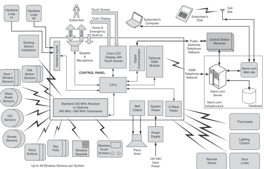
System Overview
The system’s Control Panel features a color touch screen display thatallows control of all system functions and programming. The display clearly shows the installer and subscriber system and installation status. The helpful scrolling text, along with the voice prompts that the Control Panel sounds, make installation, programming, and operation very easy compared to keypad-programmed and operated security systems of the past.
The system supports 48 wireless sensors of various types, two hardwire loops, 15 sensor response types, a supervised bell output, and a programmable solid-state control output. An on-board digital communicator reports alarms and trouble to a central monitoring station receiver via the standard telephone network. The Control Panel also supports 2-way voice communications with the Central Station.
An internal 345 MHz narrow-band radio receiver detects signals from wireless system sensors. The high-gain receiver allows for easy placement of the wireless sensors so signals can be received in even the toughest of installation environments.
When the optional Model 2GIG-XCVR2 900 MHz transceiver is installed, it sends and receives signals with accessory wireless touch screen keypads. Touch screen keypads allow remote control of the system through the same graphic interface design as the Control Panel.
For enhanced operation, an optional Model 2GIG-GSMx global system for mobile communications module (GSM radio modem) can be installed in the fi eld. With the optional GSM radio modem installed, the system will have wireless Central Station reporting capability. 2-way voice communication with the Central Station can also go “over-the-air” through the GSM radio modem.
The optional GSM radio modem also allows 2-way communications with the Alarm.com server. Through this server, subscribers can query and control their system using a computer browser from anywhere in the world. The Alarm.com server can also send messages, time corrections, and software updates to the Control Panel. Special messages from the server are displayed to the subscriber on the Control Panel’s color touch screen.
For home control, the Control Panel’s built-in Z-Wave radio module allows controlling and monitoring various home automation devices such as lighting, locks, heating, and air conditioning. The Z-Wave radio module can also activate Z-Wave remote alarm sirens. 32 User Codes including a Duress Code are supported. User “one” is the Master User Code that can add or delete the other 31 User Codes. The Installer Code must be unique from any other User Code and is the only code that has access to system programming. The front panel and buttons serve as controls as well as indicators. Pressing the button displays emergency icons on the display for Panic, Fire, and Emergency alarm activation (each has programmable options and can be enabled or disabled). Pressing the button changes the system display to the Home Screen.
C P U Piezo Siren Smoke Sensors PIR Motion Sensors Key Fobs Panic Buttons Door / Window Sensors Wireless Keypads Wireless Touch Screens
Up to 48 Wireless Sensors per System Standard 345 MHz Receiver or Optional 345 MHz / 900 MHz Transceiver CO Sensors Glass Break Sensors Hardwire Loop #1 Speaker & Microphone V oice Siren CONTROL PANEL Hardwire Loop #2 Existing Sensor Installation Hardwire Inputs Subscriber Touch Screen Digital Comm unicator Subscriber’s Computer Subscriber’s PDA Cell Site Alarm.com Web site Central Station Receiver Public Switched Telephone Network GSM Telephone Network Thermostat Z-Wave Radio Lighting Control Door Locks Remote Sirens Power Supply System Power Bell Output 120 VAC Input Power Alarm.com Server Optional GSM Module Color LCD Display with Touch Screen Color Display Home & Emergency Buttons Alarm.com Infrastructure Database
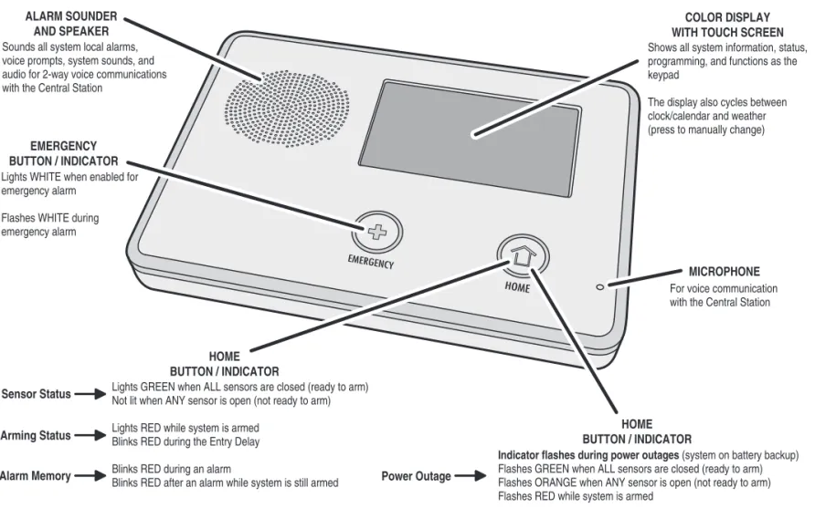
Control Panel Features
ALARM SOUNDER AND SPEAKER
COLOR DISPLAY WITH TOUCH SCREEN
MICROPHONE EMERGENCY BUTTON / INDICATOR Lights WHITE whenenabled for emergencyalarm Flashes WHITE during emergencyalarm For voice communication with the Central Station Soundsall system local alarms,
voiceprompts, systemsounds, and audio for2-way voice communications with the Central Station
HOME BUTTON / INDICATOR
Showsall systeminformation, status, programming, and functionsas the keypad
Thedisplayalso cyclesbetween clock/calendarand weather (press to manually change)
LightsGREEN when ALL sensorsare closed (ready to arm) Not lit when ANY sensoris open (not ready to arm) LightsRED whilesystemisarmed
BlinksRED during the Entry Delay BlinksRED duringanalarm
BlinksRED afteranalarm whilesystemisstill armed Sensor Status
Arming Status
Alarm Memory Power Outage
Indicator flashes during power outages (system onbatterybackup) FlashesGREEN when ALL sensorsare closed (ready to arm) Flashes ORANGE when ANY sensoris open (not ready to arm) FlashesRED whilesystemisarmed
HOME BUTTON / INDICATOR
"THIRD HAND" HANGERSTRAP
Hooks onto mountingplateduringinstallation
to hold the Control Panel while wiring
TELEPHONE LINE MONITOR TERMINALS Terminals for connecting lineman's
"buttset" formonitoring the telephone line
MAIN RECEIVER MODULE
345 MHz receiver for wirelesssensors
Optional Model XCVR2345 / 900 MHz transceiver for touch screen keypads
(XCVR2 is not for UL985 installations)
OPTIONAL GSM RECEIVER MODULE Model 2GIG-GSMx GSM Module for over-the-air
communication with the Alarm.com
Central Station
BACKUP BATTERY PACK 7.2 Volt Ni-mh batterypack isincluded
with the Control Panel, replacement
part number2GIG-BATT1
TELEPHONE JACK ForRJ45 connection to installation's RJ31X telephonejack, incomingand
outgoing lines for full lineseizure
GSM ANTENNA (HIDDEN) Internal Model 2GIG-ANT1 GSM antenna mountsin theside of the Control Panel case
TERMINAL BLOCK
Connections forpower, solidstate output
bell, and hardwire loops
For UL985 installations, use the Model 2GIG-BATT1X battery pack
Figure 4. Control Panel External Features
Installation Outline
Wireless Installation Tips
The following outline is intended to guide the installing alarmdealer through the complete installation of a Go!Control system. Use the following outline in conjunction with this copy of the Installation Instructions to guide you through the installation.
1. Unpack the system. Identify the system components.
2. Plan the installation by creating an installation fl oor plan. Determine the best centralized location for the Control Panel. Decide on where the wireless sensors will be installed.
3. Identify an un-switched 120 VAC power source for plugging in the Control Panel’s power supply.
4. Identify or install a U.S.O.C. RJ31X telephone jack for connection of the Control Panel’s communicator.
5. Use the Control Panel’s mounting plate as a template to mark the mounting location for the Control Panel. Mark any drywall cutouts behind the mounting plate required for the installation and make the cutouts.
6. Attach the mounting plate to the wall using three screws.
7. Install each of the system’s wireless sensors. If either of the two hardwire loops are going to be used, install the contacts and route the loop wire to the Control Panel’s wall cutout. Use the log in the quick programming guide to document each sensor’s ID number and location.
8. Install the optional remote sounder, and route the connection wire to the Control Panel’s wall cutout.
9. Route the telephone line from the RJ31X jack to the Control Panel’s wall cutout.
10. Using the “third hand” strap, hang the Control Panel on the mounting plate in preparation for wiring.
11. Connect all wiring to the Control Panel’s terminal block.
12. Plug the telephone line into the Control Panel’s telephone jack.
13. Plug the backup battery connector into the connector on the Control Panel’s circuit board.
14. Swing the Control Panel up, placing the bottom over the lip of the mounting bracket. Push the top of the Control Panel into the mounting bracket until it snaps into place, then secure it with the retaining screw.
15. Plug the power supply into the un-switched 120 VAC wall outlet.
16. Program the system as described in this manual and mark the check boxes in the Operation and User’s Guide to indicate any custom setup to the subscriber.
17. Test the system as described in this manual.
18. Instruct the subscriber on the system operation and provide the Operation and User’s Guide to the subscriber.
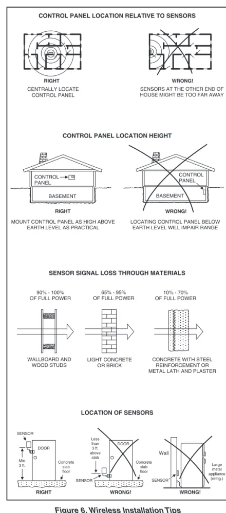
When installing any wireless system, certain limitations must be considered. Low power wireless transmitter signals will not
broadcast equally through all types of construction materials. The Control Panel contains a very sensitive receiver that should allow placement of transmitters in almost all locations.
Here are some general wireless guidelines that should be reviewed before beginning the installation. Follow these tips to create the best possible functioning wireless installation.
WRONG! RIGHT
CENTRALLY LOCATE CONTROL PANEL
SENSORS AT THE OTHER END OF HOUSE MIGHT BE TOO FAR AWAY
BASEMENT BASEMENT CONTROL PANEL CONTROL PANEL RIGHT WRONG!
LOCATING CONTROL PANEL BELOW EARTH LEVEL WILL IMPAIR RANGE MOUNT CONTROL PANEL AS HIGH ABOVE
EARTH LEVEL AS PRACTICAL
90% - 100% OF FULL POWER 65% - 95% OF FULL POWER 10% - 70% OF FULL POWER WALLBOARD AND WOOD STUDS
CONCRETE WITH STEEL REINFORCEMENT OR METAL LATH AND PLASTER LIGHT CONCRETE
OR BRICK
CONTROL PANEL LOCATION RELATIVE TO SENSORS
CONTROL PANEL LOCATION HEIGHT
SENSOR SIGNAL LOSS THROUGH MATERIALS
LOCATION OF SENSORS SENSOR Concrete slab floor DOOR Concrete slab floor DOOR Less than 3 ft. above slab Min. 3 ft. RIGHT WRONG! Wall WRONG! Large metal appliance (refrig.) SENSOR SENSOR
Wireless System Sensors
2GIG-DW10
Thin Door/Window Contact
• For narrow applications, sensor is only 3/4” wide • Fully supervised • Rare earth magnet • Lithium battery
• Supports internal and external contacts • Can be used for two
zones of protection • 345 MHz
• ETL Listed
2GIG-DW20R
Recessed Door Contact
• Compact size, only 2-1/2” long • Fully supervised
• Rare earth magnet • Lithium battery • 345 MHz • ETL Listed
2GIG-PIR1
Passive Infrared Motion Detector
• Dual element sensor with 50’ by 50’ range
• 45 lb. pet immune • 90 degree look down • Lithium battery • 345 MHz • ETL Listed
2GIG-KEY2
4-Button Key Ring Remote
• Arms system in Stay or Away Mode • Disarms system
• Auxiliary output and emergency functions • Lithium battery • 345 MHz • ETL Listed
2GIG-PANIC1
Panic Button Remote
• For triggering emergency alarm • Small and lightweight
• 5-second button lockout • Lithium battery
• 345 MHz • ETL Listed
2GIG-GB1
Glass Break Detector
• Monitors for the sound of breaking glass • Two test LEDs
• Dual shatter recognition technology (thud then crash) • Lithium battery
• 345 MHz • ETL Listed
2GIG-SMKT2
Smoke and Heat Detector
• Photoelectric-type detector with rate-of-rise and fi xed 135° heat sensors • Status indicator • Built-in 85 dBA sounder • Lithium battery
• 345 MHz • ETL Listed
2GIG-TS1
Wireless Touch Screen Keypad
• Wireless communication with Control Panel • Same graphic interface
as Control Panel
• Supports all user functions of the Control Panel • 900 MHz
• NOTE: Not for UL985 installations.
2GIG-PAD1
Wireless Keypad
• Arms system in Stay or Away Mode • Disarms system • Fire and Panic
emergency functions • Lithium batteries • 345 MHz • ETL Listed
2GIG-TAKE-345
Super Switch Wireless
Takeover Module
• Eight-channel transmitter • Converts up to eight
hardwired loops into eight wireless sensor zones • 9-16 VDC, 50 mA • Can be powered from
existing Control Panel • 345 MHz
System Accessories
2GIG-GSMx
GSM Module
• Cellular telephone module • Plugs into Control Panel • Provides 2-way GSM
radio communication
• Enrolls with cellular service provider
2GIG-ANT1
Internal GSM Antenna
• Antenna installs inside Control Panel
• Plugs into GSM module • Small size
• Locking connector
2GIG-ANT1X
External In-wall GSM Antenna
• Antenna installs in the wall behind Control Panel • 2-foot cable
• Plugs into GSM module • Locking connector
2GIG-ANT2X
External Attic Mount GSM
Antenna
• Antenna installs in attic above Control Panel • 10-foot cable
• Plugs into GSM module • Locking connector
2GIG-ANT4X
External In-wall GSM
Antenna
• Antenna installs in the wall behind Control Panel • 2-foot cable
• Plugs into GSM module • Locking connector
2GIG-BATT1
Standard Battery Pack
• Standard battery supplied with Control Panel
• Also available as a replacement item
• Nickel metal hydride (NiMH) battery
2GIG-BATT1X
Extended Battery Pack
• Optional extra capacity battery • Replaces standard internal
Control Panel battery • Required for UL985 fi re
warning system listing
• Nickel metal hydride (NiMH) battery
2GIG-AC1
Replacement Power Supply
• High effi ciency switching power supply
• 120 VAC @ 60 Hz input • 14 VDC @ 1700 mA output • Screw terminals for wiring
connecting to the Control Panel • Includes retaining bracket
Installation
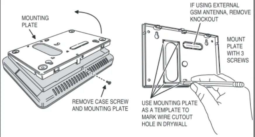
Control Panel Mounting Plate
The Control Panel should be mounted on the wall in an easy location for the subscriber to operate the system.
1. Remove the locking screw from the top of the Control Panel case and remove the mounting plate.
2. Use the mounting plate as a template to mark the wall for the wiring cutout slot. Use a drywall saw to cut the slot. If using the optional Model 2GIG-GSMx GSM module with the external Model 2GIG-ANT1X or Model 2GIG-ANT2X antenna, remove the plastic knockout labeled “EXTERNAL ANTENNA” on the mounting plate. Mark and cut a slot in the drywall for the external antenna.
3. Attach the mounting plate to the wall using three screws.
Wireless Sensors
Each wireless sensor needs to be installed at its desired location.
1. Following the instructions included with each wireless sensor, install each sensor at its desired location.
2. Use the Installation Log to document each sensor’s ID number and location.
Hardwired Loops
Hardwired loops can be programmed either normally open (N/O) or normally closed (N/C). End-of-line resistors (EOLR) can also be used to supervise the loops.
Only contacts should be used with the hardwired loops. The Control Panel does not support powering external devices (PIR’s, etc.).
✓ NOTE: HARDWIRED LOOPS CANNOT BE USED FOR A CO
OR FIRE SENSOR LOOP.
1. If either of the two hardwired loops are going to be used, install the contacts and route the loop wire to the Control Panel’s wall cutout.
2. If end-of-line supervision is required for the loop, install a 2.2K ohm resistor (not supplied) as shown in the loop illustration.
REMOVE CASE SCREW AND MOUNTING PLATE MOUNTING PLATE USE MOUNTING PLATE AS A TEMPLATE TO MARK WIRE CUTOUT HOLE IN DRYWALL IF USING EXTERNAL GSM ANTENNA, REMOVE KNOCKOUT MOUNT PLATE WITH 3 SCREWS
Figure 7. Wall Mounting Template
Figure 8. Typical Door Sensor Installation
HARDWIRE LOOP WIRING EXAMPLES
N.C. N.O. 2.2K EOLR HA R DWI R E LOOP 1 O R 2 GR OUND MIXED EOL LOOP N.O. 2.2K EOLR HA R DWI R E LOOP 1 O R 2 GR OUND N.O. EOL LOOP 2.2K EOLR N.C. HA R DWI R E LOOP 1 O R 2 GR OUND N.C. EOL LOOP N.O. HA R DWI R E LOOP 1 O R 2 GR OUND N.O. LOOP N.C. HA R DWI R E LOOP 1 O R 2 GR OUND N.C. LOOP
HARDWIRE LOOPS NEED TO BE PROGRAMMED FOR CONTACT TYPE
Installation
Remote Alarm Sounder
The Control Panel provides two terminals for an optional connection to a remote electronic alarm sounder (see Figure 10).
➜ WARNING: Do not connect an electromechanical bell to these terminals. Damage to the output will occur.
The bell terminals can be supervised. If siren supervision is enabled (Q-21), and the wire between the Control Panel and sounder is cut, the Control Panel will indicate a trouble alert for siren supervision and report bell trouble to the Central Station.
1. Install the remote sounder in a secure location where it can easily be heard.
2. Route wiring from the remote sounder location to the Control Panel’s wall cutout.
✓ NOTE: If the piezo alarm siren used for a remote sounder has an extremely low current draw and/or the sounder produces hum or noise, install an 820 Ω resistor in parallel with the sounder (see Figure 10).
Solid State Output
The Control Panel provides one solid state output that can be programmed to activate during various conditions. The output can switch up to 250 Ma @ 16 VDC to ground. Refer to Figure 11 for examples of devices wired to the output.
This output will only function while the Control Panel is receiving power from the wall power supply.
1. Install the device to be controlled by the solid state output.
2. Route wiring from the device location to the Control Panel’s wall cutout.
➜ WARNING: Do not connect an electromechanical bell to these terminals. Damage to the output will occur.
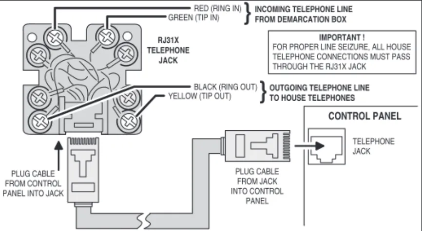
Communicator Telephone Line
Both an incoming telephone line and an outgoing telephone line will be connected to the Control Panel. When the communicator activates, all local telephones will be disconnected to prevent an off-hook telephone on the premises from blocking the communicator’s call. See Figure 12 for RJ31Xjack wiring details.
1. Run a 4-conductor telephone cable from the telephone company demarcation box to the Control Panel mounting plate.
2. At the demarcation box, disconnect the house telephones that are wired to the box output. DO NOT DISTURB THE TELCO INPUT “DROP” SIDE OF THE BOX OR ANY EARTH GROUNDS.
3. At the demarcation box, connect the RED cable wire to the box RING, and the GREEN cable wire to the box TIP.
4. At the demarcation box, connect the BLACK cable wire to the house telephone RING wire(s), and the YELLOW cable wire to the house telephone TIP wire(s).
5. At the Control Panel, connect the cable’s RED wire to the RJ31X jack’s RING IN terminal, and the GREEN wire to the RJ31X jack’s TIP IN terminal.
6. At the Control Panel, connect the cable’s BLACK wire to the RJ31X jack’s RING OUT terminal, and the YELLOW wire to the RJ31X jack’s TIP OUT terminal.
7. Snap the cover on the jack. Plug one end of the modular cable into the jack and slide it through the hole in the mounting plate into the wall.
1 K LED
OPEN COLLECTOR OUTPUT 250 mA @ 16 VDC MAXIMUM OUTPUT SWITCHES TO GROUND WHEN ACTIVATED
EXAMPLE HOOKUP SHOWING AN ARMED LED, THE OPEN COLLECTOR OUTPUT CAN BE PROGRAMMED TO ACTIVATE DURING VARIOUS CONDITIONS
8 - HARDWIRE LOOP 2 7 - HARDWIRE LOOP 1 6 - BELL (-) 5 - BELL (+)
4 - OPEN COLLECTOR OUTPUT 3 - GROUND
2 - 14 VDC POWER INPUT (-) 1 - 14 VDC POWER INPUT (+)
NOTE: FOR ETL LISTING, AN EXTERNAL DC BACKUP POWER SUPPLY IS REQUIRED FOR A LOAD CONNECTED TO TERMINAL 4
NOTE: TERMINAL 1 WILL ONLY PROVIDE DC POWER WHEN THE CONTROL PANEL'S POWER SUPPLY IS CONNECTED TO AN AC POWER SOURCE
Figure 11. Solid State Output Wiring
CONTROL PANEL
TELEPHONE JACK
RED (RING IN)
GREEN (TIP IN)
INCOMING TELEPHONE LINE
FROM DEMARCATION BOX
BLACK (RING OUT) YELLOW (TIP OUT)
OUTGOING TELEPHONE LINE
TO HOUSE TELEPHONES RJ31X TELEPHONE JACK PLUG CABLE FROM CONTROL PANEL INTO JACK
PLUG CABLE FROM JACK INTO CONTROL
PANEL
IMPORTANT !
FOR PROPER LINE SEIZURE, ALL HOUSE TELEPHONE CONNECTIONS MUST PASS
THROUGH THE RJ31X JACK
Figure 12. Telephone Jack Wiring SUPERVISED BELL OUTPUT
6-12 VDC @ 120 mA MAXIMUM PIEZO SIREN 8 - HARDWIRE LOOP 2 7 - HARDWIRE LOOP 1 6 - BELL (-) 5 - BELL (+)
4 - OPEN COLLECTOR OUTPUT 3 - GROUND
2 - 14 VDC POWER INPUT (-) 1 - 14 VDC POWER INPUT (+)
THE BELL OUTPUT CAN BE PROGRAMMED FORSUPERVISION TO DETECT IF THE WIRE TO THE BELL IS CUT
USE SOLID STATE SOUNDERS ONLY DO NOT CONNECT TO AN ELECTROMECHANICAL BELL !!!
FOR VERY LOW CURRENT SOUNDERS, INSTALL AN 820 ΩRESISTOR IN PARALLEL WITH THE SOUNDER
82
0
Ω
Installation
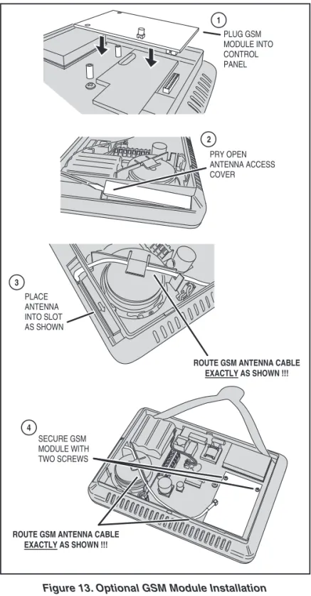
Optional GSM Module Installation
If using the optional GSM module and one of the GSM antennas. Refer to the following steps:
1. Plug the GSM module into the connector on the Control Panel’s circuit board. Secure it with the two screws.
2A. If using the Model 2GIG-ANT1 internal antenna, remove the antenna access cover. Route the antenna lead through the opening in the case and place the fl at antenna into the slot. Route the antenna wire under the clip behind the speaker and plug the antenna connector into the GSM module. Replace the antenna access cover. See Figure 13.
✓ NOTE: The routing of the GSM antenna wire is very critical. Route the wire as directed or GSM radio interference will occur inside the Control Panel.
2B. If using one of the external antennas, simply plug the antenna connector into the GSM module. The antenna will drop into the wall or mount in the attic with the cable passing through the slot in the Control Panel’s mounting plate. See Figures 14 & 15.
✓ NOTE: The GSM SIM card should have been pre-activated by the factory; if not, contact your service provider. For the GSM module to function with the system, it will have to be activated before it can be enrolled by creating an account with the service provider. 3 2 1 4 PRY OPEN ANTENNA ACCESS COVER PLACE ANTENNA INTO SLOT AS SHOWN
ROUTE GSM ANTENNA CABLE EXACTLY AS SHOWN !!! PLUG GSM MODULE INTO CONTROL PANEL SECURE GSM MODULE WITH TWO SCREWS
ROUTE GSM ANTENNA CABLE EXACTLY AS SHOWN !!!
Figure 13. Optional GSM Module Installation
ANTENNA HANGS
DOWN INSIDE WALL
2GIG-ANT1X ANTENNA
GSM CONNECTOR
Figure 14. ANT1X In-wall GSM Antenna Installation
2GIG-ANT2X GSM ANTENNA MOUNTED AS HIGH AS POSSIBLE COAX TO CONTROL PANEL
Installation
HANG CONSOLE ON STRAP
1
2
CONNECT HARDWIRE LOOPS, EXTERNAL SOUNDER, AND OPEN COLLECTOR OUTPUT TO TERMINALS
3
PLUG TELEPHONE LINE INTO TELEPHONE JACK
Figure 16. Control Panel Mounting
Control Panel Wiring
The Control Panel includes a “third hand” plastic strap that allows the unit to hang on the mounting plate during installation.
1. Hang the Control Panel on the mounting plate using the “third hand” strap (see Figure 16).
2. Connect the hardwire loop, external sounder, and open collector output wiring (if used ) to the Control Panel’s terminal block.
3. Plug the telephone line (if used ) into the connector on the Control Panel’s circuit board.
Backup Battery Connection and Power Supply Wiring
The backup battery connects to the Control Panel’s circuit board with a two-pin header assembly.
The power supply features a two-position terminal block for connecting the power supply to the Control Panel power terminals (connection wire not included).
1. Determine a good location where there’s a 120 VAC outlet for the plug-in power supply. The 120 VAC outlet must be un-switched (an outlet not controlled by a wall switch). DO NOT CONNECT THE POWER SUPPLY TO A RECEPTACLE CONTROLLED BY A SWITCH.
2. Route 2-conductor 18 AWG wire from the power supply location to the Control Panel mounting plate.
3. BEING CAREFUL TO OBSERVE POLARITY, connect the power supply’s DC + and DC - terminals to the 18 AWG wire. DO NOT PLUG IN THE POWER SUPPLY YET.
4. BEING CAREFUL TO OBSERVE POLARITY, connect the 18 AWG wire to the Control Panel +14 VDC Terminal #1 (+) and -14 VDC Terminal #2 (-) power input terminals.
✓ NOTE: Grounding of the Control Panel is NOT required for proper operation.
5. Plug the backup battery pack’s connector into the connector on the Control Panel’s circuit board. (The Control Panel will not recognize that the battery is connected until AC power is connected to the power supply.)
★ IMPORTANT: Applicable regulatory agencies require
installation of the extended life backup battery (P/N 2GIG-BATT1X) inside the Control Panel for UL985 Household Fire applications.
Control Panel and Power Supply Mounting
With all the wiring complete, the Control Panel is ready to power up.
1. Swing the Control Panel up, placing the bottom over the lip of the mounting bracket. Push the top of the Control Panel into the mounting bracket until it snaps into place, then secure it with the retaining screw.
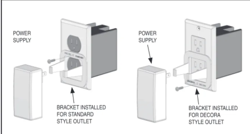
2. Peel off the adhesive backing from the power supply retaining bracket and attach the bracket to the outlet with a wall plate screw. Note the orientation for a standard or Decora style outlet (see Figure 19).
3. Spread the retaining bracket ears and plug the Control Panel’s power supply into the un-switched 120 VAC outlet. Slots are provided on the bracket to secure the power supply with a zip-tie.
4. After about fi ve seconds, the Control Panel will indicate that power has been applied. IF THE CONTROL PANEL DOES NOT POWER UP, CHECK THE POWER SUPPLY POLARITY!!!
POWER SUPPLY CONTROL PANEL TERMINALS TERMINAL #2 - 14 VDC TERMINAL #1 + 14 VDC LEFT TERMINAL + 14 VDC RIGHT TERMINAL - 14 VDC
OBSERVE POLARITY WHEN CONNECTING THE POWERSUPPLY!!!
Figure 17. Power Supply Wiring
1 CONNECT BATTERY 2 ALIGN MOUNTING PLATE INSIDE OF CONSOLE BOTTOM EDGE
3 SWING CONSOLE UP AND SNAP ONTO THE MOUNTING PLATE
4
AFTER INSTALLING,
SECURE CONSOLE WITH SCREW IN
RETAINING HOLE
Figure 18. Connecting Battery and Closing Panel
Figure 19. Securing the Power Supply BRACKET INSTALLED FOR STANDARD STYLE OUTLET POWER SUPPLY POWER SUPPLY BRACKET INSTALLED FOR DECORA STYLE OUTLET
Main Display Screens
The Control Panel is programmed and operated using the color touch-screen display. The display will show various buttons, indicators, and text to guide the installer and user.
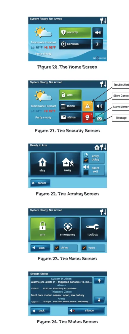
Home Screen
The Home Screen is the top level screen. It shows the system status with icons to indicate system conditions. It also displays the time and date. System information scrolls along the top of the display. The Home Screen displays the SECURITY and SERVICES buttons. The Silent Control and Display Off buttons are also displayed. When the system is operating, pressing the button on the Control Panel will display the Home Screen.
Security Screen
The Security Screen shows the system status and offers three buttons for ARM, MENU, and STATUS. The Silent Control button and the time and date are also displayed. If messages, alarm, or trouble alerts are pending, the Security Screen will display buttons indicating the number of pending messages or issues.
Arming Screen
The Arming Screen is used to arm the security portion of the system. It displays the system status and arming buttons for STAY and AWAY.
Option check boxes for ENTRY DELAY and SILENT EXIT are displayed. To arm the system without an entry delay, un-check the ENTRY DELAY check box. To arm silently without sounding the Exit Delay beeps, check the SILENT EXIT check box. Stay Mode arming always has a silent exit.
Menu Screen
The Menu Screen shows the system status and offers buttons for ARM and TOOLBOX. If any of the 24-hour emergency options are enabled, an EMERGENCY button is displayed. Two option check box buttons for CHIME and VOICE are displayed.
Installer setup can be accessed using the TOOLBOX button. The CHIME button enables/disables chimes for the entire system (chimes can be independently enabled or disabled for each sensor number from the Toolbox).
The VOICE button enables/disables voice announcements for the entire system (voice announcements can be independently enabled or disabled for each sensor number from the Toolbox).
Voice announcements always sound during alarm conditions.
Status Screen
The Status Screen lists system status and any alerts. The date and time of alerts are listed in the displayed log.
One option button for SILENCE is displayed; it temporarily stops the voice announcement of the system status during the status display.
Figure 20. The Home Screen
Figure 22. The Arming Screen
Figure 23. The Menu Screen
Figure 24. The Status Screen Figure 21. The Security Screen
Trouble Alert
Alarm Memory Silent Control
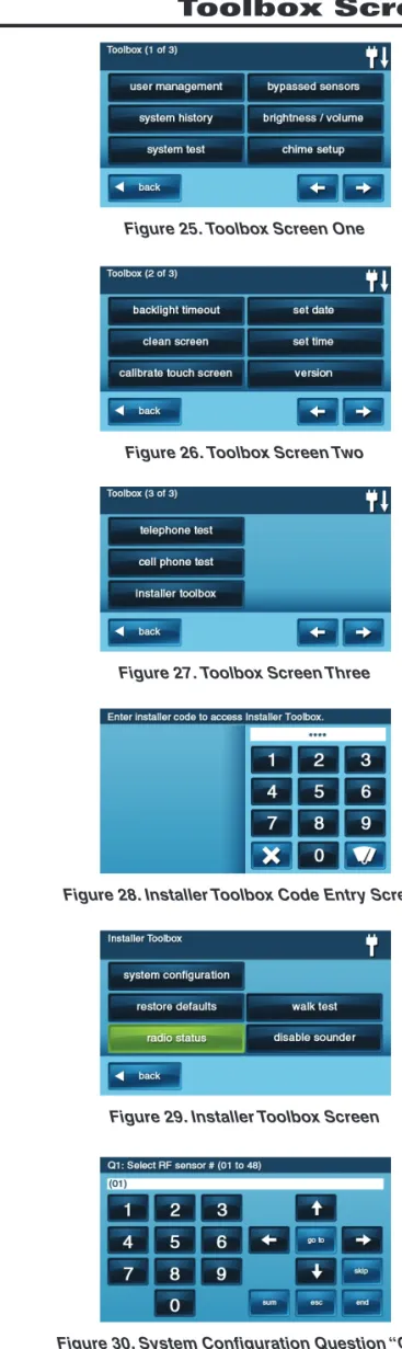
Toolbox Screens
The Control Panel is programmed using the “toolbox” screens.Users can access basic programming functions. Installers can access basic and Installer Toolbox functions. Users and installers must enter a valid code to access the programming functions in the toolbox. Other functions do not require entering a code.
Toolbox Screens
From the Menu Screen, when the TOOLBOX button is pressed, the system will ask for a User Code then display Toolbox Screen one. The arrow button displays Toolbox Screens two and three. Each Toolbox Screen shows option buttons that display sub-menus.
Installer Code Entry Screen
The INSTALLER TOOLBOX button goes to the main programming area of the Control Panel and can only be accessed by the installer
while the system is disarmed by entering a correct access code.
THE INSTALLER CODE CANNOT DISARM THE SYSTEM.
The system features a special shortcut to help the installer access the Installer Toolbox quickly. Pressing the lower right corner of the Home Screen while the system is disarmed will immediately display a code entry screen. When the correct Installer Code is entered, the system will go directly to the Installer Toolbox.
Installer Toolbox Screen
The Installer Toolbox Screen displays system setup and testing buttons. Main programming is accessed using the SYSTEM CONFIGURATION button. The other buttons support system tests and resetting the Control Panel to its programming default values.
System Confi guration Screen
When the SYSTEM CONFIGURATION button is pressed, the Control Panel will display questions for each programming step. To help the installer program the Control Panel quickly, the programming questions are arranged so that the commonly set values appear early in the question order.
Figure 25. Toolbox Screen One
Figure 26. Toolbox Screen Two
Figure 27. Toolbox Screen Three
Figure 28. Installer Toolbox Code Entry Screen
Figure 29. Installer Toolbox Screen
System Status Icons
The top line of the Control Panel’s display is the status bar that shows the current system mode, the status of the sensors, and any current system trouble alerts. Special icons are displayed to visually show the system’s current condition.
AC Power Icon
The AC power icon indicates the Control Panel’s AC line power status. The icon displays a white plug when the AC power is present; the icon will display with a red “X” over the white plug when AC power is absent.
Phone Line Failure Icon
If the Control Panel detects that the telephone line is disconnected, the phone line failure icon will be displayed.
Sounder Disable Icon
If the system’s internal sounder has been lowered and external sounder has been disabled by the installer for testing, the sounder disable icon will be displayed. Also fl ashes to indicate silent arming.
Backup Battery Status Icon
If the Control Panel’s backup battery tests low, the low backup battery icon will be displayed.
Test Mode Icon
When the system is being tested in Walk Test Mode, the test mode icon will be displayed on the status bar.
Touch Screen Keypad Traffi c Icon
When the Control Panel is communicating to a touch screen keypad the up arrow icon is displayed. When a touch screen keypad communicates to the Control Panel the down arrow icon is displayed.
GSM Radio Icon
If the system’s optional GSM radio modem is installed, the GSM radio icon will be displayed while the Control Panel is receiving over-the-air fi rmware updates.
Interior Sensor Open Icon
If an interior sensor is open (or a motion detector has just been activated) the house icon will be displayed on the status bar. As a warning, the icon fl ashes during arming.
Figure 31. System Status Bar
STATUS BAR SHOWING
AC POWER IS ON
Figure 32. AC Power Icons
AC POWER ON AC POWER OFF
Figure 33. Phone Line Failure Icon
PHONE LINE FAILURE
Figure 34. Sounder Disable Icon
SOUNDER DISABLED
Figure 35. Backup Battery Status Icon
LOW BACKUP
BATTERY
Figure 36. Test Mode Icon
SYSTEM IN TEST MODE
Figure 37. Touch Screen Keypad Traffi c Icon
COMMUNICATION IN PROCESS
Figure 38. GSM Radio Icon
OVER-THE-AIR UPDATE IN
PROCESS
Figure 39. Interior Sensor Open Icon
INTERIOR SENSOR OPEN
Programming Navigation
Figure 40. Navigation Arrows & Go To Button
Figure 41. Questions without Sub-options
Figure 42. Questions with Sub-options
Figure 43. Questions with Data to Enter
Figure 44. Other Buttons Displayed When the installer is using the System Confi guration menus,
the Control Panel will present each programming question sequentially. Most programming questions have a single numeric value response or a simple enabled/disabled selection. Some programming questions have sub-options that can be set. These sub-options are displayed for the question selected and can be accessed through navigation keys on the display.
Navigation Arrows & Go To Button
The programming question screens display up, down, left, and right navigation arrows. They are used to move through the programming questions and sub-options.
The GO TO button is used to jump directly to a programming question. Pressing GO TO will prompt the installer for the two-digit question number to jump to. The GO TO button changes to CANCEL while waiting for a question number, press CANCEL to back out.
Questions without Sub-options
Most of the programming questions do not have sub-options. They navigate as follows. Questions without sub-options do not display a SKIP button.
• The ↑ & ↓ arrows select the next or previous programming question. • The ← & → arrows choose values for the question or move the cursor left
and right along the white data entry fi eld.
Questions with Sub-options
Some of the programming questions have sub-options. They navigate as follows. Questions with sub-options display a SKIP
button during the question.
• The SKIP button advances to the next programming question/section. • The ↑ & ↓ arrows select the next or previous programming sub-question. • The ← & → arrows choose values for the question or move the cursor left
and right along the white data entry fi eld.
Questions with Data to Enter
Some of the programming questions require entering numeric or alphabetic data. For devices that can be named, the Control Panel contains a large vocabulary with words to choose from (see Pg. 19).
• The INSERT button displays a word from the vocabulary. The words can be scrolled through using the ← & → arrows, or selected by entering their 3-digit index number.
• The (backspace) button moves the cursor to the left, deleting the one character at a time.
• The (delete) button deletes a character to the right of the cursor, or any characters that are highlighted.
• The FWD (forward) button highlights the next word in multi-word data fi elds. • The BACK button highlights the previous word in multi-word data fi elds. The
BACK button displays the previous screen in some cases.
• When the SHIFT button is displayed, pressing it will display alternate characters on the keypad that can be used for data entry.
Other Buttons Displayed
Depending on the programming question, other buttons may be displayed. • The ESC (escape) button serves as an “undo”. Pressing ESC restores the
value that was previously stored for the question or sub-question.
• The SUM (summary) button displays a summary of the values stored for the programming question and sub-options.
• The END button displays a summary of the values stored for the entire Control Panel memory.
• The LEARN button is used to set the system to receive a sensor’s serial number when transmitted during programming the wireless sensors. • The PASTE button repeats the last sensor serial number entered. • The EXIT button exits programming.
Each system installed will require programming. Most installations being performed by the professional alarm installer for a specifi c organization will have common values set in every Control Panel reporting to the same Central Station. Other programming values, such as the account number and sensor setup, will be unique for each installation.
Following is an outline to guide the professional alarm installer through the programming of the Control Panel.
If you don’t read anything else, read this outline! Use the following outline in conjunction with this copy of the Installation and Programming Instructions to guide you through the installation.
Because of the many programming options available with this Control Panel, thoroughly reading this manual is very important. Understanding the Control Panel’s programming structure will help to save time during each installation.
At this stage, all the wireless and hardwired sensors should be installed, and the Control Panel should be mounted, connected, and powered-up.
1. Start at the Home Screen.
2. Press the logo at the lower right corner of the screen. (The Installer Toolbox can also be accessed via the third screen of the System Toolbox.)
3. Enter the Installer Code (default = 1561) to display the Installer Toolbox.
4. Press SYSTEM CONFIGURATION and begin programming as described on Page 18.
5. USE THE INSTALLATION LOG SHEET TO RECORD PROGRAMMED VALUES FOR THE SYSTEM.
6. After setting all the required programming values for the sensors and the Control Panel, press END, then EXIT, to save the changes.
7. After the Control Panel restarts, press SECURITY, MENU, TOOLBOX, enter the Master User Code (default = 1111), press USER MANAGEMENT and setup the user’s codes. Be sure to set a Duress Code as User #8. Press BACK when fi nished.
8. Press BRIGHTNESS / VOLUME and set the levels for the installation. The volume setting DOES NOT affect the volume of alarm sounds.
9. Press ➜ to view the second toolbox screen.
10. Press BACKLIGHT TIMEOUT and set the display lighting timeout.
11. Press SET DATE and SET TIME and set the calendar and clock. (If the GSM module is installed, the date and time are set automatically.)
12. Press the button to return to the Home Screen.
After all setup and programming, refer to the Operation and User’s Guide for details on operating the system. Check off the programmed options for the system in the User’s Guide.
Be sure to instruct the subscriber on the proper operation of the system, and leave the User’s Guide at the installation site for reference.
SIA CP-01 Defaults
Several system programmable options have the defaults pre-set to provide compliance with the Security Industry Association CP-01 Standard. All other system settings and functions that are required to comply with SIA CP-01 are permanently programmed into the Console and cannot be changed. Refer to the table for each programmable option that has a required SIA CP-01 programming default.
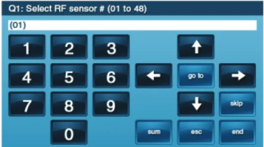
Programming Outline
Figure 47. Installer Toolbox Screen
Figure 48. System Confi guration Question “Q-1”
PROGRAMMING QUESTION SIA CP-01 DEFAULT RANGE
Q-1 Wireless Sensor Dialer Delay 30 Seconds On or Off Q-2 Wired Sensor Dialer Delay 30 Seconds On or Off Q-5 Exit Delay 60 Seconds 45-120 Seconds Q-6 Entry Delay #1 30 Seconds 30-240 Seconds Q-7 Entry Delay #2 45 Seconds 30-240 Seconds Q-10 Call Waiting Disable Code No Default Code 0-6 Digits Q-20 Swinger Shutdown Count 2 Trips 1-6 Trips Q-26 Auto Stay Enabled Enabled or Disabled Q-27 Exit Delay Restart Enabled Enabled or Disabled Q-31 Cancel Time 5 Minutes 6-254 Minutes Q-32 Cancel Display Enabled Enabled or Disabled Q-35 Abort Window Dialer Delay 30 Seconds 15 or 45 Seconds Q-78 Select Output Follows Internal Sounder See Q-78 for Options
Figure 45. The Home Screen
Press logo to access
the Installer Toolbox
Figure 46. Toolbox Screen Three
Installer Toolbox canbe
Programming Question Table
Q # QUESTION DEFAULT Q-1 Select RF sensor # (01-48) Q-1 SU B -Q UESTIONSSelect RF sensor (#) type (00) unused Select RF sensor (#) equipment type Varies by RF sensor type
(Only shown for some sensor types) Select RF sensor (#) equipment code (0000) other
Enter RF sensor (#) other equipment code (0-9999) 0 (Only shown if other is selected) Enter RF sensor (#) serial number (7 digits) 0000000
Select RF sensor (#) equipment age (0-1) (0) new
Select RF sensor (#) loop number (1-3) Varies with sensor model selected Select RF sensor (#) dialer delay (0-1) ‡ (1) enabled (except for fi re & CO) Construct RF sensor (#) voice descriptor No default
Select RF sensor (#) reports (0-1) (1) enabled Select RF sensor (#) supervised (0-1) (1) enabled Select RF sensor (#) chime (0-5) (0) disabled Q-2 Select wired sensor # (1-2)
Q-2 SU
B
-Q
UESTIONS
Select wired sensor (#) type (00) unused
Select wired sensor (#) equipment type Varies by wired sensor type (Only shown for some sensor types) Enter wired sensor (#) equipment code (0-9999) 0
Select wired sensor (#) equipment age (0-1) (0) new Select wired sensor (#) normal state (0) not used Select wired sensor (#) dialer delay (0-1) ‡ (1) enabled Construct wired sensor (#) voice descriptor No default Select wired sensor (#) reports (0-1) (1) enabled Select wired sensor (#) chime (0-5) (0) disabled Q-3 Select fob # (1-8) Q-3 SU B -Q UESTIONS
Select fob (#) used (0-1) (0) unused Select fob (#) equipment code (0000) (0000) other
Enter fob (#) other equipment code (0-9999) 0 (Only shown if other is selected) Enter fob (#) serial number (7 digits) 0000000
Select fob (#) equipment age (0-1) (0) new Select fob (#) emergency key (0-4) (0) disabled Select fob (#) key 2 can disarm (0-1) (1) enabled Construct fob (#) voice descriptor keyfob # Select fob (#) arm no delay (0-1) (0) disabled Select fob (#) key 4 output (0-2) (0) disabled Q-4 Select RF keypad # (1-4)
Q-4 SU
B
-Q
UESTIONS
Select RF keypad (#) used (0-1) (0) unused Select RF keypad (#) equipment code (0000) other
Enter RF keypad (#) other equipment code (0-9999) 0 (Only shown if other is selected) Enter RF keypad (#) serial number (7 digits) 0000000
Select RF keypad (#) equipment age (0-1) (0) new Select RF keypad (#) emergency keys (0-1) (1) enabled Construct RF keypad (#) voice descriptor keypad # Q-5 Enter exit delay, in seconds (45-120) ‡ 60 seconds Q-6 Enter entry delay 1, in seconds (30-240) ‡ 30 seconds Q-7 Enter entry delay 2, in seconds (30-240) ‡ 45 seconds Q-8 Select dialer (0-1) (0) disabled Q-9 Enter dialing prefi x (0-4 digits) No default Q-10 Enter call waiting disable code (0-6 digits) ‡ No default Q-11 Enter CS #1 phone number (0-25 digits) No default Q-12 Enter CS #1 account number (4 digits) No default Q-13 Select 2-way voice (0-2) (1) stay on line Q-14 Select silent panic/burglary listen only (0-1) (1) enabled Q-15 Select dialing type (0-1) (0) touch tone Q-16 Select police emergency key (0-2) (1) audible Q-17 Select fi re emergency key (0-1) (1) audible Q-18 Select emergency key (0-1) (1) audible Q-19 Select quick arming (0-1) (1) enabled Q-20 Select swinger shutdown count (1-6) ‡ (2) two trips Q-21 Select siren supervision time (0-3) (0) disabled Q-22 Enter CS lack of usage notifi cation time (0-255) 7 Days Q-23 Enter radio modem network failure time (0-255) 30 minutes Q-24 Select radio modem network failure causes trouble (0-1) (1) enabled Q-25 Select radio modem network failure reports (0-1) (1) enabled Q-26 Select auto stay (0-1) ‡ (1) enabled Q-27 Select exit delay restart (0-1) ‡ (1) enabled
Q # QUESTION DEFAULT
Q-28 Select quick exit (0-1) (1) enabled Q-29 Enter periodic test, in days (0-255) 30 days Q-31 Enter cancel time, in minutes (5-255) ‡ 5 minutes Q-32 Select cancel display (0-1) ‡ (1) enabled Q-33 Select cross sensor 47-48 (0-1) (0) disabled Q-34 Enter cross sensor timeout, in seconds (10-120) 10 seconds Q-35 Select abort window dialer delay (0-2) ‡ (1) 30 seconds Q-36 Select burglary bell cutoff (0-4) (0) 4 minutes Q-37 Select fi re bell cutoff (0-4) (0) 4 minutes Q-38 Enter time to detect AC loss, in minutes (0-30) 10 minutes Q-39 Select random AC loss report time (0-1) (1) enabled Q-40 Enter CS #2 phone number (0-25 digits) No default Q-41 Enter CS #2 account number (4 digits) No default Q-42 Select remote control phone (0-3) (3) data and voice Q-43 Enter installer code (4 digits) 1561 Q-44 Select lock installer programming (0-2) (0) disabled Q-45 Select lock default programming (0-2) (0) default all Q-46 Select trouble doesn’t sound at night (0-1) ♦ (1) enabled Q-47 Select trouble resound after holdoff (0-7) (0) disabled Q-48 Enter download csid (6 digits) 000000 Q-49 Select programming mode entry reports to CS (0-1) (0) disabled Q-50 Select trouble reports to CS (0-1) (1) enabled Q-51 Select manual bypass reports to CS (0-1) (0) disabled Q-52 Select AC loss reports to CS (0-1) (1) enabled Q-53 Select system low battery reports to CS (0-1) (1) enabled Q-54 Select RF low battery reports to CS (0-1) (1) enabled Q-55 Select opening reports to CS (0-1) (0) disabled Q-56 Select closing reports to CS (0-1) (0) disabled Q-57 Select alarm restore reports to CS (0-1) (0) disabled Q-58 Select trouble restore reports to CS (0-1) (1) enabled Q-59 Select bypass restores reports to CS (0-1) (0) disabled Q-60 Select AC restore reports to CS (0-1) (1) enabled Q-61 Select system low battery restore reports to CS (0-1) (1) enabled Q-62 Select RF low battery restores reports to CS (0-1) (1) enabled Q-63 Select phone fail detect (0-1) (0) disabled Q-64 Select smart test reports (0-1) (0) disabled Q-65 Select RF jam causes trouble (0-1) (0) disabled Q-66 Select daylight saving (0-1) (1) enabled Q-67 Select daylight saving start month (01-12) (03) March Q-68 Select daylight saving start Sunday (1-7) (2) 2nd Q-69 Select daylight saving end month (01-12) (11) November Q-70 Select daylight saving end Sunday (1-7) (1) 1st Q-71 Select system tamper causes trouble (0-1) (1) enabled Q-72 Select quick bypass (0-1) (0) disabled Q-73 Select disarming keyfob after alarm (alert) (0-1) (0) disabled Q-74 Select keyfob arm / disarm confi rmation (0-1) (0) disabled Q-75 Select auto unbypass for manual bypass (0-1) (1) enabled Q-76 Select force bypass reports (0-1) (0) disabled Q-77 Select event log (0-3) (3) all events
Q-78 Select output (00-10) ‡ (11) follows internal sounder alarm Q-79 Select Z-Wave feature (0-3) (1) disabled but visible Q-80 Select Z-Wave switches feature (0-1) (0) disabled Q-81 Select Z-Wave thermostats feature (0-1) (0) disabled Q-82 Select Z-Wave door locks feature (0-1) (0) disabled Q-83 Select temperature display units (0-1) (0) degrees Fahrenheit Q-84 Select services require master code (0-1) (0) disabled Q-85 Select master user access to zwave toolbox (0-1) (0) disabled Q-86 Select disable siren after two-way audio (0-1) (0) disabled
Q-87 Select keyfob/remote arming mode on system not ready (0-2)
(0) auto-bypass with zone participation on restore Q-88 Select siren mode (0-1) (0) sound for burglary and fi re/CO
‡ Default set for SIA CP-01 compliance
System Sensor Types
Each sensor (wireless or wired) installed in the system is programmed to a specifi c sensor number and sensor type ( zone). The sensor number identifi es the specifi c sensor when it is displayed on the Control Panel, recorded in the event log, or reported to the Central Station. This allows pin-point information about any sensor in the system.
The sensor type determines how and when the Control Panel responds to signals from the sensor. Some sensors are armed all the time, others are armed only in certain arming levels, some cause Central Station reports any time they are activated. The sensor’s type, along with other programming options, determine this.
Sensor Types (Zones)
(00) Unused
This is the setting for unused sensor numbers that do not have a sensor programmed into them. No system action occurs at any time from this sensor type.
(01) Exit/Entry 1
This sensor type is reserved for doors that are used for exit and entry of the protected premises. When the system is armed in the Away Mode or Stay Mode, the Exit Delay timer starts. There is an Exit Delay regardless of whether the system is armed in Stay Mode or Away Mode. When the Exit Delay timer expires, the system is fully armed.
With the system fully armed, when this type of sensor is triggered, the Entry Delay #1 timer starts. The system must be disarmed before the Entry Delay #1 time expires, or an alarm will occur.
If the Entry Delay is turned off during arming, the exit/entry delay sensors will act as non-delayed instant sensors at the end of Exit Delay.
(02) Exit/Entry 2
This sensor type operates the same as the Exit/Entry 1 sensor type except it will start the Entry Delay #2 timer. This provides a method of having a longer Entry Delay on certain openings, such as a garage door, to provide the user more time to disarm the system.
(03) Perimeter
This sensor type is for perimeter doors and windows that will not be used to enter or exit the protected premises while the system is armed.
An instant alarm will occur when this type of sensor is triggered with the system armed in either the Stay Mode or Away Mode.
(04) Interior Follower
This sensor type is for interior sensors such as motion detectors, mat switches, interior doors, and other sensors that detect human presence inside the protected premises.
This type of sensor is called a “follower” due to its action when the system is armed in the Away Mode. After the Exit Delay expires and the system is armed, if an interior follower sensor is triggered, an instant alarm will occur. If an exit/entry delay sensor is triggered fi rst, the interior follower sensor will also be delayed. Interior follower sensors are always bypassed and not active when the system is armed in Stay Mode. This allows the premises to be occupied while still protecting the perimeter.
(05) Day Zone
This sensor type is the same as a perimeter zone, except when the system is disarmed, a violation displays a trouble alert on the Console’s display.
Common uses for this sensor type are protection of sensitive areas that require notifi cation and possibly a Central Station trouble report, but not an alarm when the system is disarmed.
(06) 24-hour Silent Alarm
This sensor type is active independent of the system arming status. The code for silent panic is sent to the Central Station, but for safety, there are no visual or audible indications locally that this sensor type has been triggered.
(07) 24-hour Audible Alarm
This sensor type is continuously armed 24-hours a day. A sensor programmed to this type will trigger a local alarm and the bell output regardless of the mode the system is in. Typical use would be an audible panic alarm.
(08) 24-hour Auxiliary Alarm
This sensor type is continuously armed 24-hours a day. A sensor programmed to this type will trigger an alarm regardless of the mode the system is in. The bell output will not activate, but the local sounder will continue until it’s acknowledged at the Control Panel. Typical use would be for a monitoring device such as a fl ood or temperature sensor. There is no timeout for the internal sounder, it will continue until a User Code is entered.
(09) 24-hour Fire
†
This sensor type is continuously armed 24-hours a day. A sensor programmed to this type will trigger the local alarm fi re sounder and the bell output regardless of the mode the system is in. Typical use would be for wireless smoke detectors. This sensor type is always active and cannot be bypassed.
(10) Interior with Delay
This sensor type operates as a delayed sensor when the system is armed in the Away Mode, and when triggered, will start the Entry Delay #1 timer. If the system is armed in Away Mode with no Entry Delay (armed instant), this sensor type will trigger an instant alarm.
If the system is armed in Stay Mode (or Stay Mode with no Entry Delay), this sensor type will be bypassed.
(14) 24-hour Carbon Monoxide
†
This sensor type is continuously armed 24-hours a day. A sensor programmed to this type will trigger the local alarm pulse sounder and the bell output regardless of the mode the system is in. Typical use would be for wireless carbon monoxide detectors. This sensor type is always active and cannot be bypassed.
(16) 24-hour Fire with Verifi cation
†
This sensor type is continuously armed 24-hours a day. A sensor programmed to this type can trigger the local alarm fi re sounder and the bell output regardless of the mode the system is in. Typical use would be for wireless smoke detectors. This sensor type is always active and cannot be bypassed.
For verifi cation, this sensor type must be violated twice in two minutes, or remain violated for 30 seconds. If any other fi re sensor (verifi ed sensor type or not) violates within two minutes, both sensors will cause a fi re alarm.
(23) No Response Type
This sensor type is a special zone that can be monitored for activity or inactivity by the Central Station. It does not affect security system status.
(24) Silent Burglary
This sensor type is for silent triggering the burglary alarm with perimeter doors and windows that will not be used to enter or exit the protected premises while the system is armed. The Control Panel’s sounder and the bell output will not activate.
An instant silent alarm will occur when this type of sensor is triggered with the system armed in either the Stay Mode or Away Mode.
† Indicates Sensor types that are not allowed for hardwired loops.