Copyright © 2014 CTTS.IN, All right reserved
Modeling and control of MPPT Based Grid Connected
Wind-PV Hybrid Generation System
S.Chandra Shekar
PhD Scholar, Electrical and Electronics Engineering, Koneru Laxmaih University, Vijayawada, India Email: [email protected]
K.Raghu Ram
Professor, Laqshya Institute of Technology and Sciences, Khammam, India Email: [email protected]
Abstract — When the power demand increases power failure also increases so the renewable energy can be used to provide constant loads. To convert the basic circuit equation of solar cell into simplified form a model is developed including the effects of changing solar irradiation and temperature. Maximum power point tracking control strategy is used to extract the maximum power output of photovoltaic power generation system. This paper reports the development of a computer simulation approach for evaluating the general performance of stand-alone wind / photovoltaic generating systems and also describes the solar-wind hybrid system for supplying electricity to power grid. The simulation results show the control performance and dynamic behavior of the hybrid wind-PV system.
Keyword — Wind power generation system, solar PV system, grid interface inverter, MPPT
1. INTRODUCTION
The rise in the cost of conventional fossil fuel is making supply-demand of electricity product almost impossible especially in some remote areas. Generators which are often used as an alternative to conventional power supply systems are known to be run only during certain hours of the day, and the cost of fueling them is increasingly becoming difficult if they are to be used for commercial purposes. There is a growing awareness that renewable energy such as photovoltaic system and Wind power can play an important role in overcoming this situation. The Solar-generated electricity is called Photovoltaic (or PV). Photovoltaics are solar cells that convert sunlight to D.C electricity. These solar cells in PV module are made from semiconductor materials. When light energy strikes the cell, electrons are emitted. The electrical conductor attached to the positive and negative scales of the material allow the electrons to be captured in the form of a D.C current. The generated electricity can be used to power a load or can be stored in a battery.
Wind Power is energy extracted from the wind, passing through a machine known as the windmill. Electrical energy can be generated from the wind energy. This is done by using the energy from wind to run a windmill,
which in turn drives a generator to produce electricity [1]. The windmill in this case is usually called a wind turbine. This turbine transforms the wind energy to mechanical energy, which in a generator is converted to electrical power. An integration of wind generator, wind turbine, aero generators is known as a wind energy conversion system. Wind power is one of the fastest growing renewable energy technologies around the world.
PV modules and wind turbines are now widely used in developed countries to produce electrical power in locations where it might be inconvenient or expensive to use conventional grid supplies, while other homeowners who choose the renewable energy sources prefer to connect their energy system to the grid system. J.A. Gow et.al [2] discussed in Development of a photovoltaic array model for use in power-electronics simulation studies. Kim [3], developed a grid-connected photovoltaic model using PSCAD/EMTDC for electromagnetic transient analysis. Any power system that incorporates two or more of the following is referred to as a hybrid power system: PV panels, wind turbines. For small loads, the most common combinations are PV-wind hybrid system. PV and PV-wind is good match, because inland wind speeds tend to be lower in summer, when solar energy can compensate, and higher in winter, when sunshine falls to very low levels. The model of a small wind-fuel cell hybrid energy system and analyzed life cycle of a wind-fuel cell integrated system [4]. H.L Tsai represented as model of photovoltaic module using Matlab/Simulink[5].
Copyright © 2014 CTTS.IN, All right reserved
2. MODEL OF
HYBRID
WIND/PV
SYSTEM
WITH GRID
A hybrid energy system usually consisting of or more renewable energy sources [7] are used together to provide increased system efficiency as well as greater balance in energy supply. In this paper, the hybrid energy system is a photovoltaic array coupled with a wind turbine. Figure-1 shows the schematic diagram of proposed system. The developed system consists of two 100KW photovoltaic array and 100 KW double field induction generator wind turbine connected to grid system for achieving the maximum power point with a current reference control produced by P&O algorithm. Wind turbine, asynchronous induction generator, Turbine and Drive model and DC-DC Boost converter. The proposed block diagram and simulation representation is shown in figure1 and Simulation representation of Proposed System shown in fig 2.
Fig. 1. Schematic diagram of the proposed system
Fig. 2. Simulation representation of Proposed System
3. MODELING OF PHOTOVOLTAIC CELL
In PV panels solar cells are the basic components and it is made of silicon. A solar cell is generally a p-n junction which is made of silicon. It is made up of two different layers when smaller quantities of impurity atoms are added to it. A PV system convert’s sunlight in to electricity and the PV cell is the basic device of the photovoltaic system. Number of Cells are combined and grouped to form PV panels or modules and form large photovoltaic arrays [6]. The solar arrays are the combination of number of cells connected in series or in parallel group of panels to get required power generation.
There are many stages used in grid connected PV system like PV array, DC to DC converter, DC to AC converter [9]. In this paper a model is developed through converting common circuit equation of solar cell in to simplified form including the effects of changing solar irradiation and changing temperature. In this paper a control approach for interfacing the PV array with DC-DC converter. The power injected into the grid from the PV panel through two stages. In first stage in order to enhance the DC voltage level of PV panel the PV array is connected to the DC-DC converter. The MPPT is used to track the maximum power point in order to achieve the maximum power point. In second stage through grid connected inverter control dc power is converted into ac power and also this control the current and power injected from the grid.
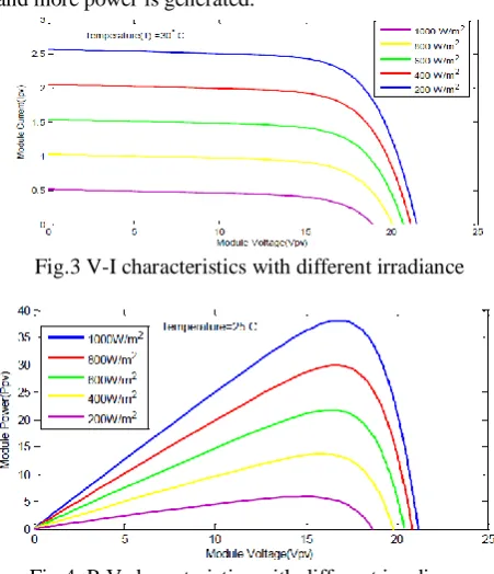
The Voltage vs Power characteristics and Voltage vs Current characteristics of a solar cell mainly depends upon the solar irradiation shown in fig 3and 4. If there is a change in the environmental condition then the solar irradiation level changes which results different maximum power. So maximum power point tracking algorithm is used to maintain the maximum power constant if there is any change in the solar irradiation level. If the solar irradiation level is higher, then the input to the solar cell is more which results more magnitude of the power with the same voltage value. When there is increase in the solar irradiation the open circuit voltage increases. Because, when there is more solar light fall on the solar cell, with higher excitation energy the electrons are supplied, they increase the mobility level of electron and more power is generated.
Fig.3 V-I characteristics with different irradiance
Fig.4. P-V characteristics with different irradiance
Copyright © 2014 CTTS.IN, All right reserved undesirable feature. As fig.5 illustrates P-V
characteristics with different temperature and the increase in temperature the open circuit voltage decreases which results the increase in the band gap so more energy is required to cross the barrier. As a result the solar cell decreases its efficiency.
Fig.5 P-V characteristics with different temperature
4. MAXIMUM POWER POINT TRACKING
In solar panel peak power is archived with the help of a DC-DC boost converter and it is used between the PV generator and the load by adjusting the duty cycle. Maximum Power Point of a solar module varies with the variation of irradiation and temperature So MPPT algorithms are necessary in PV applications because by the use of MPPT algorithms it obtains the peak power from the solar panel. Previously there are different methods to find the MPP that has been published and developed. There are number of MPPT algorithms are there among these techniques. The Incremental conductance algorithms and the P&O algorithms are generally used. This is easy to use and simple in operation and requires less hardware as compared to other. In this paper, perturbation and observation algorithm is used for maximum power point tracking. The circuit arrangement of maximum power point tracking is shown in fig 6 and flow chart representation of perturbation and observation algorithm illustrated in fig7.
Fig.6. Circuit Arrangement of MPPT
If there is change in power which is positive the voltage will increase in the right hand side direction similarly if it is negative or decreases then the voltage perturbation will be in the opposite that is left ward direction. So the direction of the perturbation is decided whether the voltage at present is higher than voltage at previous one, accordingly due to this change in power control signal of
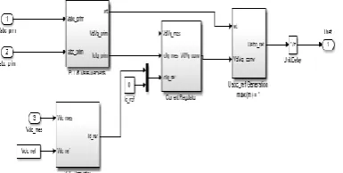
the PWM can be calculated. According to this algorithm, overshoot appears in the starting and slowly decreases till it reaches a stable steady state. The control action will stop only when the output power reach its maximum values. In this model, whereas the inputs are the solar irradiation and cell temperature, the outputs are the photovoltaic voltage and current. The proposed simulation model is represented by MPPT Controller using perturbation and observation technique shown in Fig 8. A MPPT controller model is built and implemented using MATLAB, to operate the PV module at its maximum power point. Fig 9 illustrates implementation of the PV control system model. The P&O algorithm requires two measurements: measurement of the current (Ipv) and measurement of the voltage (Vpv). The proposed model is implementation as shown in Fig.10
Copyright © 2014 CTTS.IN, All right reserved Fig.8. MPPT Controllers using Perturb & Observe
technique
Fig.9. Implementation of the PV control system model
5. WIND TURBINE
Wind energy is capable of supplying large amount of power and the total amount of obtainable power available from the wind is considerably more than the present human power used from all the sources. Wind power is an alternative to fossil fuels, is plenteous, widely expanded, clean, and renewable and during operation no greenhouse gas are produced. Wind power is the fast growing source of energy. A moving force is exerted and generates lift when wind is passing over the blades. The rotating blades rotate the shaft which is connected with the gearbox. The gearbox adjusts the rotational speed which is convenient for the generator to get a desired output. The output of the wind generator is fed to the transformer which converts the electricity of the generator up to 33 KV which is the appropriate voltage for power system. Mechanical power transfer to the shaft is equal to
Where power coefficient (Cp). The proposed wind turbine
and drive model as shown from fig.9 and also implementation of DC-DC Boost converter is shown in Fig 10.
Fig. 9. Implementation of the Turbine and Drive model
Fig.10. Subsystem implementation of DC-DC Boost converter
Due to the variations in wind speed, the output power of the wind turbine induction generator experiences variations in frequency and amplitude. Therefore, a controllable ac/dc converter is used to smooth the wind turbine output power before being supplied to other electronic devices. The subsystem implementation of excitation, speed and pitch control illustrated in Fig.11 and fig.12.
Fig.11. Subsystem implementation of speed and Pitch control
Fig.12. Sub systems for excitation control
6
.
SIMULATION RESULTS AND DISCUSSION
The major inputs for the proposed PV model were solar irradiation, PV panel temperature and PV manufacturing data sheet information. The PV-wind system specifications are listed in Table I and Table II.
Table 1 : Solar Module (100KW) Specification
Rating 37.06V
Current at Peak 7.71A Voltage at Peak 26.6V Short circuit current 8.36A Open circuit voltage 33.2V Number of Cells per Module 54 Number of series connected modules per
string 8
Copyright © 2014 CTTS.IN, All right reserved Table II: Wind generation Specification
Rating 100KW Diameter 8 m Number of blades 3 Cut in speed of wind 11m/s Cut out speed of wind 25 m/s Generator Rating 50Kw Nominal Voltage 260V Generator frequency 50Hz
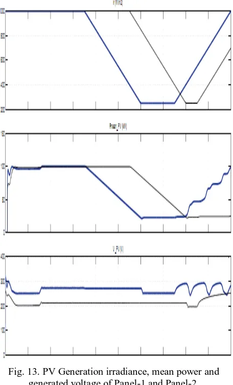
PV Generation irradiance, mean power and generated voltage of Panel-1 and Panel-2 are shown in fig 14.
Fig. 13. PV Generation irradiance, mean power and generated voltage of Panel-1 and Panel-2.
The wind turbine output voltage, mechanical power, active and reactive power represented from fig 14 to fig 17and total power generation of PV-wind shown in figure 18.
Fig.14. Wind generation output voltage
Fig.15. Wind turbine mechanical power in pu
Fig 16: Wind turbine active power generation
Fig.17. Wind turbine reactive power
Copyright © 2014 CTTS.IN, All right reserved
9. CONCLUSION
In this paper, grid connected hybrid wind/solar PV generation system has been presented. It is observed that the extraction of the maximum power from PV array is obtained using MPPT system. The Perturb and observe (P&O) algorithm has been implemented. The proposed system has been simulated in MATLAB-SIMULINK environment. The dynamic behavior of the proposed model is examined under different operating conditions. Solar irradiance, temperature and wind speed data is gathered from a 200KW grid connected solar power system and 100KW wind power generation. The proposed model offers a proper tool for smart grid performance optimization.
REFERENCE
[1] Technical brief on Wind Electricity Generation: Retrieved from www.windpower.org ,(2009) [2] J.A. Gow, and C.D. Manning, “Development of a
photovoltaic array model for use in power-electronics simulation studies,” IEE Proceedings- Electric Power Applications, vol. 146, pp. 193-199, Mar. 1999.
[3] S.K. Kim, J.H. Jeon, C.H. Cho, E.S. Kim, and J.B. Ahn, “Modeling and simulation of a grid-connected PV generation system for electromagnetic transient analysis, ”Solar Energy, vol.83, pp. 664- 678, May 2009.
[4] M.J. Khan, and M.T. Iqbal, “Dynamic modeling and simulation of a small wind fuel cell hybrid energy system,” Renewable Energy, vol. 30, pp. 421-439, Mar. 2005.
[5] H.L Tsai, “Isolation-oriented model of photovoltaic module using Matlab/Simulink,” Solar Energy, vol. 84, pp. 1318-1326, July 2010 [6] J.A. Gow, and C.D. Manning, “Development of a
photovoltaic array model for use in power-electronics simulation studies,” IEE Proceedings- Electric Power Applications, vol. 146, pp. 193-199, Mar. 1999.
[7] M.J. Khan, and M.T. Iqbal, “Dynamic modeling and simulation of a small wind fuel cell hybrid energy system,” Renewable Energy, vol. 30, pp. 421-439, Mar. 2005.
[8] O.C. Onara, M. Uzunoglua, and M.S. Alam, “Dynamic modelling, design and simulation of a wind/fuel cell/ ultra-capacitor-based hybrid power generation system, “Journal of Power Sources, vol. 161, pp. 707-722, Oct. 2006.
[9] N. Chayawatto, K. Kirtikara, V. Monyakul, C. Jivacate, and D. Chenvidhya, “DC–AC switching converter modelling of a PV grid-connected
system under islanding phenomena,” Renewable Energy, vol. 34, pp. 2536-2544, Dec. 2009
S. Chandra Sekhar received his B.Tech Degree in Electrical & Electronics Engineering from RVR&JC college of Engineering; GUNTUR in 2001, M.Tech (High Voltage Engineering) degree in Electrical and Electronics Engineering from University College of Engineering, JNTU, Kakinada in 2004.He is pursuing Ph.D at K L University. Presently he is working as associate professor and Head of the Department of EEE. He has publications in Eight international journals. He is guiding both undergraduate and post graduate student projects. His area of interest includes Micro Grids, High voltage transmission and Power Systems