20
Smart Distance Measurement Device Using
Ultrasonic Sensors
Sagun Rungta
1, Pushpendra Tiwari
2, Varun Bhandari
3, Ms. Priyanka Sharma
41,2,3
Department of EIE, Galgotias college of Engineering and Technology, Dr. A.P.J. Abdul Kalam Technical University.
4
Assistant Professor Department of EIE, Galgotias college of Engineering and Technology, Dr. A.P.J. Abdul Kalam Technical University.
ABSTRACT
Distance measurement plays a vital role in engineering, science, business. The distance is always measured between two points. Generally distance measurement is possible only by making contact with the target whose distance is to be measured, but this paper discusses the measurement of distance without making contact with the target. This is done by generating 40 kHz ultrasonic waves using ultrasonic transducers. Here the distance is calculated on the basis on time taken by the pulse generated by the ultrasonic transducer to travel to the target and return as reflected echo. This device also makes the use of microcontroller for calculating the distance and displaying it on a seven segment display. The distance up to 2.5m is calculated in air medium at ambient temperature
Keywords: Distance measurement, ultrasonic transducers, microcontroller, seven segment display
INTRODUCTION
Measurement is a factor that is frequently used in ones daily life. Generally measurement is finding a number that shows size or amount of a particular entity. Measure of an entity can be judged by its magnitude and dimension (unit). The distance is measured using scale, ruler, measuring tape etc which needs physical contact with the target whose distance is to be measured. The distance measurement has three important factor .i.e. and medium, source, target. The source is a point from where distance is to be measured and target is the object whose distance is to be measured. The medium lies between source and target. This paper discusses the measurement of distance without contacting the target. This is made possible through the ultrasonic waves. Ultrasonic is a application of ultrasound. The ultrasound is a vibration of frequency which is greater than the upper limit of human hearing range. Generally ultrasound has frequency ranging from 20 kHz to several GHz. Ultrasound has its application in many fields. It is used in medicine for imaging known as sonography. In industries it is used in certain chemical processes and also used to detect flaws in structures and products.
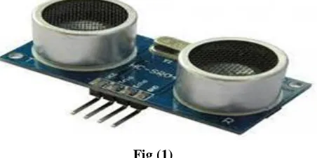
One of the applications of distance measurement is used here. The ultrasonic distance meter makes the use of ultrasonic transducer as shown in fig. 1. The ultrasonic transducer [1] is as device that converts any form of energy into ultrasonic vibration
21
The ultrasonic distance meter consists of a transmitter unit, a receiver unit, a microcontroller AT89C2051 [2], a seven segment display which displays the calculated distance. [Fig (2)]
Figure 2. Schematic diagram of transmitter and receiver Literature Review
Distance measurement is the process of comparing. Distance measurement is a important factor used in almost every field. Distance can be measured using several methods. Generally it is measured using measuring tapes, ropes, rulers etc. Apart from these methods it can also be measured optically and electro-magnetically. Optical measurement was made possible by Sir James watt. In electromagnetic measurement method [3] distance is measured on the basis of the time taken by the radio wave to travel a certain distance. Measurement of distance by infrared rays is also possible [4]. Reviews of the previous literatures of ultrasonic distance meter were studied and understood for the development of this project. The conclusion drawn was that the ultrasonic was used in various areas such as under water, sewage blockage detection [5], measuring the water level [6]. The device can also be used in automotive applications [7].
METHODOLOGY
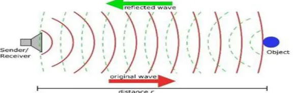
The ultrasonic distance meter account the amount of time taken by measures the distance by taking into account the amount of time taken by the pulse to travel to a target and return as reflected echo and also the speed of the pulse. The device calculates the distance upto 2.5m and at a temperature of 25*C and displayed on a seven segment display. Here two ultrasonic transducers are used one each Ai transmitting and receiving end. A microcontroller AT89C205 is used which act as the brain of the device which carries out all the major functioning’s. The system consist of a transmitter circuit and a receiver circuit, the details of which are described below. Fig(3) shows the principle of ultrasonic distance meter.
The ultrasonic distance meter consists of a transmitter unit, a receiver unit, a microcontroller AT89C2051 [2], a seven segment display which displays the calculated distance. [Fig (3)]
22 Transmitter
Inputs are given as input to the two terminals of the ultrasonic transducer at the transmitting end. One of the input given to the terminal of the transducer is the positive going pulse and the other terminal is given 180 phase shi The transmitter section consist of a transistor which amplifies the 40KHz pulse generated by the microcontroller. The ultrasonic transducer which is used as a transmitter is driven by a inverting buffer. A set of three parallel inverter are used to increase the transmitted power. The output of this set of parallel inverters are given as input to the another set of parallel inverters. Then the output of both these parallel inverters ft of the same input. This is done in order to increase the transmitted power. Thus the ultrasonic transducer at the transmitting end generates a 40KHz pulse which hits the target and return back as reflected echo.
Reciever
The reflected echo from the target is picked up by the receiver. The echo received by the receiver is very weak and is amplified through various stages of amplifier. The first stage is a buffer with a unity fed to its non-inverting terminal. The first stage is coupled to the second stage through a capacitor. The second stage is an inverting amplifier and the third stage is a precision rectifier amplifier. The output of the amplifier is filtered and then given to the pin12 of microcontroller which is an analogue comparator, pin 13 is another terminal of the microcontroller. For displaying a particular digit on segment display the microcontroller provides segment data and display enable signal in a time multiplexed mode. A switch is used here to reset the microcontroller which drives the reset signal through a set of capacitor and resistor. The arrival of the echo signal from the target makes port3.6 of the microcontroller high which is sensed by the microcontroller. Hence the timer is read and the 16 bit number is divided from the velocity of sound to obtain the four digit number. This four digit number is displayed on the seven segment display which indicates the distance of target. sound to obtain the four digit number. This four digit number is displayed on the seven segment display which indicates the distance of target.[fig(4)]
Fig. 4. Detailed block diagram of ultrasonic distance meter
The ultrasonic transducers gives out beam of sound waves. The fig(5) is showing the beam pattern of the ultrasonic signal. It has more energy in main lobe and less energy on the side lobes. The side lobes have enegy 60db below the main lobe, but this sides lobe can also be picked up by the receiver. Hence the transmitter and receiver are spaced 5 cm apart.
23 Software
The programme is written in assembly language and microcontroller 8051 is used to assemble. The programme is written such a way thay it is easy to understand. To generate a pulse frequency of 40KHz a pulse train of 0.5s is initiated by making pin 8 of the microcontroller low and high for 12.5s. After 25 -such pulses have passed, a waiting time is given to avoid direct echoes for about 20 µs. Then the signal is awaited, while the timer runs counting time in microseconds. When the echo arrives, port-3 pin P3.6 goes high, the timer reads and the 16-bit number is divided by twice the velocity and converted into decimal format as a 4-digit number. If the echo does not arrive even after 48 milliseconds, the waiting loop is broken and the pulse train sequence is started once again. If the echo comes within this time, it is displayed for another measurement. Thus, the display appears continuous and flicker-free.
RESULT
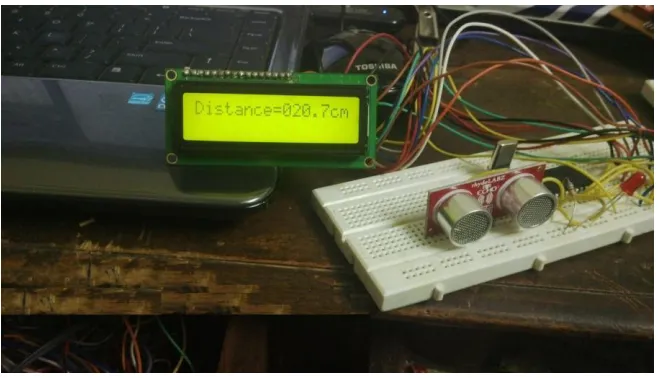
Actual Circuit has been shown below:
Figure 6. The Actual Circuit Diagram
The table (1) shows the some of the distance calculated by the device which is compared to the actual distance measured by the scale.
Table 1. Comparison of Distance measured by the device with the actual distance
S. No. ACTUAL DISTANCE (cm) MEASURED DISTANCE(cm)
1. 5 5.25
2. 10 11.36
3. 20 22.47
4. 25 25.52
CONCLUSION
24
of this system. The ultrasonic detection range also depends on the size and position of the target. The bigger is the target, stronger will be the reflected signal and more accurate will be the distance calculated. Hence the ultrasonic distance meter is an extremely useful device.
REFERENCES
[1]. Magori, V., "Ultrasonic sensors in air," Ultrasonics Symposium, 1994. Proceedings., 1994 IEEE , vol.1, no., pp.471,481 vol.1, Oct. 31 1994-Nov. 3 1994
[2]. Muhammad Ali Mazidi & Janice Gillispie Mazidi, “The 8051 Microcontroller and Embedded System”, Pearson Education, 2000
[3]. H. He, and J. Liu, “The design of ultrasonic distance measurement system based on S3C2410,” Proceedings of the IEEE International Conference on Intelligent Computation Technology and Automation, Oct. 2008
[4]. Xiao Chan, Chenliang Wu, “Ultrasonic Measurement System with Infrared Communication Technology”, vol.6, pp 2648-2675, nov 2011.
[5]. A. K. Shrivastava, A. Verma, and S. P. Singh, “Partial automation of the current sewer cleaning system,” Invertis Journal of Science and Technology, Vol. 1, No. 4, 2008, pp. 261-265.
[6]. Sabuj Das Gupta, Islam Md. Shahinur, Akond Anisul Haque, Amin Ruhul, Sudip, “Design and Implementation of Water Depth Measurement and Object Detection Model Using Ultrasonic Signal System”, International Journal of Engineering Research Volume 4, Issue 3 (October 2012), PP. 62-69
[7]. Alessio Carullo and Marco Parvis, “An Ultrasonic Sensor for Distance Measurement in Automotive Applications” IEEE 2001 sensors journal, vol. 1, no. 2, pp.143147,August 2001
[8]. S.P. Bhumkar, V.V. Deotare, R.V.Babar “Accident Avoidance and Detection On Highways” International Journal of Engineering Trends and Technology- Vol-3, Issue-2, pp.247-252,201