http://www.sciencepublishinggroup.com/j/pamj doi: 10.11648/j.pamj.20170603.11
ISSN: 2326-9790 (Print); ISSN: 2326-9812 (Online)
Design of ALU and Code Converter Using Matrix
Calculation
Nirina Gilbert Rasolofoson, Raoelina Andriambololona
Theoretical Physics Department, Institut National des Sciences et Techniques Nucléaires (INSTN-Madagascar), Antananarivo, Madagascar
Email address:
[email protected] (N. G. Rasolofoson), [email protected] (R. Andriambololona), [email protected] (R. Andriambololona), [email protected] (R. Andriambololona), [email protected] (R. Andriambololona)
To cite this article:
Nirina Gilbert Rasolofoson, Raoelina Andriambololona. Design of ALU and Code Converter Using Matrix Calculation. Pure and Applied Mathematics Journal. Vol. 6, No. 3, 2017, pp. 89-100. doi: 10.11648/j.pamj.20170603.11
Received: April 3, 2017; Accepted: April 15, 2017; Published: May 27, 2017
Abstract:
Arithmetic Logic Unit (ALU) is a fundamental building block of a central processing unit (CPU) in any computing system. The ALU is the hardware that performs logical (and, or, xor) and basic arithmetic (addition, subtraction, multiplication, division) operations. Thus, its construction requires techniques in which the treatment of operands should be consistent with operations rules. In this paper, ALU based on matrix calculation introduced and developed by Raoelina Andriambololona is proposed. These techniques aim to remove illogic and inconsistent appearing in the international writing numeration with the usual rules in arithmetic. We also propose the design of code converters which convert Binary to BCD (Binary Coded Decimal) code and vice versa using matrix calculation.Keywords:
ALU, Arithmetic, Numeration, Matrix Calculation, Code Converter1. Introduction
There are incoherencies and illogical between usual written numeration and arithmetic rules. For instance, in English language, the number 216 is written as two one six but read as two hundred sixteen (i.e. "261" instead of 216). In many languages (English, French, German, Malagasy) the same inconsistency exists [2-3-4].
In order to avoid these problems, Raoelina Andriambololona has investigated and used matrix calculation and linear algebra tools [1-2-3-4-13]. This approach exhibits four and only four possibilities to write a number according to the disposition in row matrix or column matrix and in decreasing or increasing order. It has been shown by Raoelina Andriambololona that the writing in line from Left (L) handside to the Right (R) handside by increasing (i) order (LRi disposition) is more logical and coherent with the basic arithmetic operations rules than the international which starts from the left (L) handside to the right (R) handside by decreasing (d) order (or LRd). For instance, the number 216 written in usual one (LRd disposition) is written as 612 in LRi disposition. Thus, new rules for the addition, subtraction, multiplication and division operation which are homogeneous
and consistent with the LRi disposition are established [2-3]. Raoelina Andriambololona’s work has led him also to the study of the problem of numeral basis change by using the basis change in a linear space through a passage matrix.
The result thus obtained is simpler and more direct than the usual one utilizing the euclidian successive division [3-6]. These results are helpful for the construction of supercomputer system. This leads us to design new ALU and code converters which follow new rules established using matrix calculation. In this work, the components of the arithmetic unit such as addition, subtraction, multiplication and division of the proposed ALU are explicited and designed according to LRi disposition. As for the code converters, we only use full adders to perform calculations from the change of basis matrix.
2. Utilization of Matrix Calculation in
Numeration and Arithmetics
2.1. Matrix Representation for Writing Numeration and Numeral Basis Change
The matrix formalism consists to consider the numeral representation of a number as a matrix representation of an intrinsic number in a basis which represents the numeral system. The LRi disposition is shown to be more logical and consistent with the arithmetic operations rules than the usual one which is LRd. According to LRi writing, an intrinsic
number N will be written as a row
matrix ⋯ ⋯ from left (L)
handside to the right (R) handside by increasing (i) order in the basis numeral system with radix with the vector basis [1-3].
= ⋮
⋮
= ⋯ ⋯ . (1)
In the change of radix ′ represented by vector basis ′
′ = ′ ′ ⋮ ′ ′ ′ ⋮ ′
is given by
= . (2) where the change of basis matrix is . Therefore, the writing of the number in the radix b' will be
⋯ ⋯ . (3)
Example 1: the number usually spelt as ninety thousand two hundred and thirty one in the usual language is written in the numeral system with the radix 10
= 13209 = 1 3 2 0 9 10 10 10$
10%
10& Example 2: Convert 74 into binary.
The matrix representing the basis change from radix 10 to radix 2 is
)1010 * = )1 0 0 00 1 0 1*
$+ 2 2 2$ 2% ,
Hence the writing in binary basis of the decimal number is
74 = 74 )1 0 0 00 1 0 1*
$= +
1 1 0 10
0 0 1 0 0 0 0 0 0 0 0 0 1 1 1 1 1 0 1
↪ /01234056 57 5821 4056 = 111101$
It may be checked easily
111101$= 1 × 2 + 1 × 2 + 1 × 2$+ 1 × 2%+ 0 × 2&
+ 1 × 2:= 74
Example 3: Convert 153; into hexadecimal.
Provided with the change of basis matrix of the two basis
8→16= <
1 0 8 0 0 4>?
(4)
we have
153;= 153 <
1 0 8 0 0 4> ?
= + 9 2
C 9 E
↪
= 9E ?
where the hexadecimal numbers
are 0, 1, 2, 3, 4, 5, 6, 7, 8, 9, D, E, F, G, H, I.
2.2. Utilization of Matrix Calculation in Arithmetics 2.2.1. Rules for Addition
These rules are obtained from [4]. We have for two positive integer D and A′
D = KLMDN = ∑PQ P P (5)
D′ = KLMD′N = ∑PQ ′P P (6) We can suppose 6′ > 6 with ′ ≠ 0 for 6 + 1 ≤ 0 ≤ 6′, without loosing in generality.
D + D = KLMD + D N = U P P PQ
+ U P P
V
PQ
- If P+ ′P< , then we have "P= P+ ′P is the element at the M0 + 1NY column (from the left handside) of the matrix KLMD + D N.
- If P+ ′P> we perform the decompositions
"P= PZ Z+ ⋯ + P + P with PZ<
"P P= PZ Z P+ ⋯ + P P+ P P
without summation on i. The element at the M0 + 1NY column from the left handside of KLMD + D N is "P= P while the remainders P , P$, ⋯ are to be brought respectively at the M0 + 2NY , M0 + 3NY , ⋯ M0 + \ + 1NY column (from the left) of KLMD + D N.
Example 4: perform the addition of 12610 and 9386810. The
intrinsic number D and D′ are
D = 1 2 6 . . 10 10 10$
. .
D = 9 3 8 6 8 10 10 10$
10%
10&
The dot. represents 0 (zero). The addition rules are easily obtained and may be compared with the usual one LRd.
Proposed disposition: LRi Usual disposition: LRd
carry → 1 0 1 0 0 1 0 1 ← carry
+ 1 2 6 . . + . . 6 2 1
9 3 8 6 8 8 6 8 3 9
0 6 4 7 8 8 7 4 6 0
↪ direction of operation direction of operation ↩
↪ direction of the writing ↪ direction of the writing
2.2.2. Rules for Subtraction
The subtraction of a number D" from a number D is the research of the number D′ such as D" = D + D′. It is the
inverse operation of addition. We can also use the inverse of the addition operation and establish the LRi procedure. The rules can be obtained by analogy with the addition rules. [2]
Example 5: subtract 0647810 from 12610
Proposed disposition: LRi Usual disposition: LRd
-0 6 4 7 8
-
8 7 4 6 0
0 1 0 1 0 ← carry 0 1 0 1 0 ← carry
1 2 6 . . . . 6 2 1
9 3 8 6 8 8 6 8 3 9
↪ direction of operation direction of operation ↩
↪ direction of the writing ↪ direction of the writing
2.2.3. Rules for Multiplication
Let be
D × D = KLMDD′NE = ∑ M ′NPQ" P P (8) For the explicit calculation, we proceed as for the case of the addition in respecting the places
D × D = U ^ U _ `′ _ `Q
a
"
Q
D × D = + U M P b′N
P bQ
+ U M P b′N $ $
P bQ
+
D × D =⋯
D × D = + + $ $ (9) In the calculation of the component MD × D′NP, of the product D × D′, which must be strictly less than b, we must bring the remainder in the partial sum. [2]
Example 6: multiply 51810 by 521610
Proposed disposition: LRi Usual disposition: LRd
x 5 1 8 . x . 8 1 5
5 2 1 6 6 1 2 5
5 7 0 4 4 0 7 5
0 3 6 1 1 6 3 0
Proposed disposition: LRi Usual disposition: LRd
0 9 8 4 4 8 9 0
5 7 8 1 9 9 4 4 9 9 1 8 7 5
↪ direction of operation direction of operation ↩
↪ direction of the writing ↪ direction of the writing
2.2.4. Rules for Division
The division is the inverse operation of multiplication. The division of a number A" by a number A is the operation which gives the number A′ such as A" = A × A′ [2]. According to the LRi procedure its rules differ radically from the usual one which starts from the left handside to the right handside by decreasing order LRd. The division starts from left handside by subtracting the least significant digit of the dividend from the divisor. Then we shift the divisor one place to the right and perform again the subtraction. Shifts end to the right where the
most significant digit is. If the remainder is still greater than the divisor, we repeat the same operation from the left handside to the right handside until getting remainder less than the divisor. The final result is obtained from the addition of the partial quotients.
The advantages of this method are that it respects the writing numeration and the inverse operation of the multiplication according to the LRi disposition. In addition, we can usually get from the beginning the remainder.
Example 7: division of 993210 by 410
Proposed disposition: LRi Usual disposition: LRd
9 9 3 2 4 2 3 9 9 4
6 3 9 2 0 5
3 6 3 2 3 9 9
↓ 6 3 + 9 3 6 + 9
↓ 0 0 2 3 9
↓ 0 2 5 3 6 9
3 . . . 9 9 5 . . . 3 5 9 9
↪ direction of operation ↪ direction of operation
↪ direction of the writing ↪ direction of the writing
Example 8: division of 473810 by 2110
Proposed disposition: LRi Usual disposition: LRd
4 7 3 8 2 1 8 3 7 4 1 2
8 0 1 9 7 2 6
6 6 2 8 1 1 7 4
8 0 1 9 1 0 8 + 9
6 8 1 7 . . 9 4
0 6 5 8 4 7
6 8 1 1 + 1 0 6 9 7
8 0 1 9 ↪ direction of operation
8 7 0 1 ↪ direction of the writing
6 9 8
8 1 1 .
8 0 1 9
0 1 7 9 6
↪ direction of operation
↪ direction of the writing
Example 9: division of 110910 by 15410
Proposed disposition: LRi Usual disposition: LRd
1 1 0 9 1 5 4 9 0 1 1 4 5 1
9 5 0 4 9 4 5 1 1
2 5 9 4 + 4 5 0 1 +
Proposed disposition: LRi Usual disposition: LRd
2 4 4 . 9 1 . 4 4 2 1 9
↪ direction of operation ↪ direction of operation
↪ direction of the writing ↪ direction of the writing
Example 10: division of 506310 by 140210
Proposed disposition: LRi Usual disposition: LRd
5 0 6 3 2 0 4 1 3 6 0 5 1 4 0 2
4 0 8 2 2 2 8 0 4 2
1 0 8 . 8 0 1
↪ direction of operation ↪ direction of operation
↪ direction of the writing ↪ direction of the writing
3. Application of Matrix Calculation in
Arithmetic Circuits
3.1. Design of Arithmetic Logic Unit (ALU)
An ALU typically has three input words which are the two input operands, denoted by D and E, and the carry-in input 3P . The output words are the result c and the carry-out 3deY. Besides data inputs and outputs, an ALU must have control inputs to specify the operations to be performed. All these data are coded in Binary.
The major parts of ALU are [7-10]:
- Arithmetic block: This block is used to perform four arithmetic operations such as addition, subtraction, multiplication and division;
- Logic block: This block is used to perform simple bitwise logic operations such as AND, OR, XOR, XNOR, NAND, NOT and etc;
- Multiplexers: These blocks are used to select the appropriate inputs for the arithmetic and logic blocks
Figure 1. Block Diagram of one-bit ALU.
Here we apply the new rules established for arithmetic using matrix calculation and LRi writing to construct the components of the ALU’s arithmetic unit which are addition, subtraction, multiplication and division.
3.1.1. Binary Addition - Subtraction
Let D M , ⋯ , N$ and E M , ⋯ , N$ be two n-bit numbers respectively. As the rules for arithmetic operations are similar for any basis binary, the addition is performed by adding bit by bit the components located at the same row of the matrix representing and bringing an eventual carry at the next row. [2-8].
Example 11: addition of 10012 and 11012.
carry → 0 1 1 0 1
+ 1 0 0 1
1 1 0 1
0 0 1 0 1
↪ direction of operation
The structure performing the addition of two n-bits numbers is realized from 1-bit full adder.
Figure 2.One-bit Full Adder.
The results are expressed as
Table 1.One-bit Full Adder Truth Table.
g h ijk l imno
0 0 0 0 0
0 0 1 1 0
0 1 0 1 0
0 1 1 0 1
1 0 0 1 0
1 0 1 0 1
1 1 0 0 1
1 1 1 1 1
We can have multi-bit Full Adder from the one-bit Full Adder by chaining the carry bits, such that 3P pqr = 3deYp, as shown in Figure 3.
Figure 3. Block diagram of n-bits Full Adder according to LRi disposition.
The multi-bit Full Adder can be represented simply as follows
Figure 4. Block diagram of n-bits Full Adder according to LRi disposition.
Having an Adder which operatesA - B, then subtractor performing B tA, using 2’s complement theory, is obtained by inverting the subtrahendA and adding one: B tA B -A -1. Besides theA and B inputs, we have introduced a control input Op. When this signal is 0, the circuit performs addition. When it is 1, the circuit becomes a subtractor. [10-11]
Figure 5. One-bit Full Adder / Subtractor.
Its truth table is shown in the table below
Table 2. One-bit Full Adder - Subtractor Truth Table.
g h wx l imno
0 0 0 0 0
0 0 1 0 0
0 1 0 1 1
0 1 1 1 0
1 0 0 1 0
1 0 1 1 0
1 1 0 0 0
1 1 1 0 1
The same way as the n-bits Full Adder we can have the following structure
Figure 6. Block diagram of n-bits Full Adder – Subtractor according to LRi disposition.
3.1.2. Binary Multiplication
The multiplication is realized by performing the addition of the partial product with itself shifted 1 bit to the right in each step until n times. Partial product is equal to the multiplicand when the concerned multiplier is 1 if not it is 0 for multiplier set 0. [2-8]
Example 12: 01012 by 1012 multiplicand →
x 0 1 0 1
multiplier → 1 0 1
0 1 0 1
0 0 0 0
0 1 0 1
0 1 0 0 1 1
↪ direction of operation
As the partial products can be performed with AND logical and their sum by n-bit full adders multiplier circuit performingA 9 B is shown in figure 7 [12]
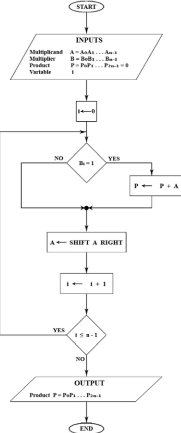
In order to make this technique straightforward to implement in programmable logic the algorithm below is helpful.
Figure 8. Binary Multiplication Algorithm.
3.1.3. Binary Division
The binary division follows the same rules as the decimal division by starting the subtraction of the dividend by the divisor from the left handside and shifting 1 bit to the right the divisor in every step. The final result is obtained by the sum of the partial quotients. [2]
Example 13: division of 10110002 by 01002
1 0 1 1 0 0 0 0 1 0 0
0 1 0 0 1
1 1 0 1 0 0 0
0 1 0 0 1
1 1 1 0 0 0 0
0 0 0 0 0
1 1 1 0 0 0 0
0 0 0 0 0
1 1 1 0 0 0 0 +
0 1 0 0 1
1 0 1 0 0 0 0
0 1 0 0 1
1 0 0 0 0 0 0
0 0 0 0 0
1 0 0 0 0 0 0
0 0 0 0 0
1 . . . 0 1 1 0
↪ direction of operation
Example 14: division of 11110002 by 11002
1 1 1 1 0 0 0 1 1 0 0
1 1 0 0 1
0 0 1 1 0 0 0
1 1 0 0 1
0 1 1 0 0 0 0
0 0 0 0 0
0 1 1 0 0 0 0
0 0 0 0 0
0 1 1 0 0 0 0 +
1 1 0 0 1
1 1 0 0 0 0 0
0 0 0 0 0
1 1 0 0 0 0 0
0 0 0 0 0
1 1 0 0 0 0 0
0 0 0 0 0
1 1 0 0 0 0 0
1 1 0 0 1
. . . 1 0 1 0
↪ direction of operation These examples show that
- Binary division is a cascade of subtraction and shift operations;
- The quotient is equal to the inverse of the last borrow of the subtractions.
The divisor circuit is thus constructed using subtractors in which multiplexers are integrated to select the output of the subtraction. Adders are used to sum the partial quotients.
Figure 9. One-bit Subtractor-Multiplexer.
Figure 10. 2: 1 Multiplexer.
Table 3. 2: 1 Multiplexer Truth Table.
y h i z
0 0 0 0
0 0 1 0
0 1 0 1
0 1 1 1
1 0 0 0
1 0 1 0
1 1 0 1
1 1 1 1
The output D is expressed as
G = / 6/ 3 51 6/ 3 (12)
Cascading the subtractor-multiplexer modules permits the subtraction of the dividend from the divisor and the generation of the quotient of the division:
- The modules first subtract the dividend from the divisor from the least significant bit on the left handside. If the subtraction output borrowing r} is zero, that is, the dividend is greater than the divisor; setting the input control bits c of each module to this value allows the calculation of the division remainders which are the new dividend. Otherwise, if r} =1, the subtraction result will not be considered and the new dividend will be the same as the previous. After each subtraction operation the divisor is shifted 1 bit to right until the subtraction of the most significant bit. If the dividend is still greater than the divisor we repeat the same process which starts from left until we get dividend less than the divisor. - Each subtraction matches a quotient bit which is the
inverse of the output borrowing r} .
- The final quotient of the division is the sum of the partial quotients ∑ r}
Considering these factors and the new rules established for division, the figure 11 shows the divisor circuit according to the LRi disposition.
Figure 11. Block diagram of four-bits divisor according to LRi disposition.
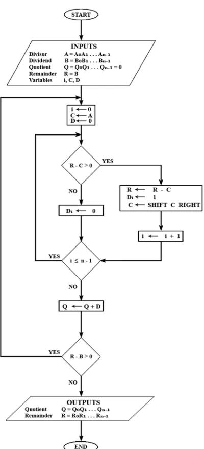
Figure 12. Binary Division Algorithm.
The components of the arithmetic unit are done according to the new rules established for the basic arithmetic operations.
3.2. Design of Code Converters
After operation results from the ALU outputs are usually coded in binary. It is sometimes necessary to use the output of one system as the input to another. A conversion circuit should be inserted between the two systems if each uses different codes for the same information. Thus, a code converter is a circuit that makes the two systems compatible even though each uses a different code. This particular section deals with the design of binary to BCD (Binary Coded Decimal) code converter and vice versa using matrix calculation.
For practical purposes decimal system can be represented in BCD or Binary Coded Decimal which represents the 10 decimal digits in terms of binary numbers in arithmetic circuits.
Table 4. Binary and BCD encoding according to LRi writing.
Binary Code Decimal
Code BCD Code
0 0 0 0 00 0 0 0 0 0 0 0 0
1 0 0 0 10 1 0 0 0 0 0 0 0
0 1 0 0 20 0 1 0 0 0 0 0 0
1 1 0 0 30 1 1 0 0 0 0 0 0
0 0 1 0 40 0 0 1 0 0 0 0 0
1 0 1 0 50 1 0 1 0 0 0 0 0
0 1 1 0 60 0 1 1 0 0 0 0 0
1 1 1 0 70 1 1 1 0 0 0 0 0
0 0 0 1 80 0 0 0 1 0 0 0 0
1 0 0 1 90 1 0 0 1 0 0 0 0
0 1 0 1 01 0 0 0 0 1 0 0 0
1 1 0 1 11 1 0 0 0 1 0 0 0
0 0 1 1 21 0 1 0 0 1 0 0 0
1 0 1 1 31 1 1 0 0 1 0 0 0
0 1 1 1 41 0 0 1 0 1 0 0 0
1 1 1 1 51 1 0 1 0 1 0 0 0
The number 857 will be represented, for instance, by 000110101110•€•. In BCD, counting is always performed in radixb 10, that is the greatest digit of the 4-bit binary string is9 1001$. Consequently we have to make correction when exceeding 9 by adding 6 (0110) to generate carry brought to next row. [9]
Considering this last condition, we can apply the matrix calculation method to convert binary numbers into BCD number and vice versa.
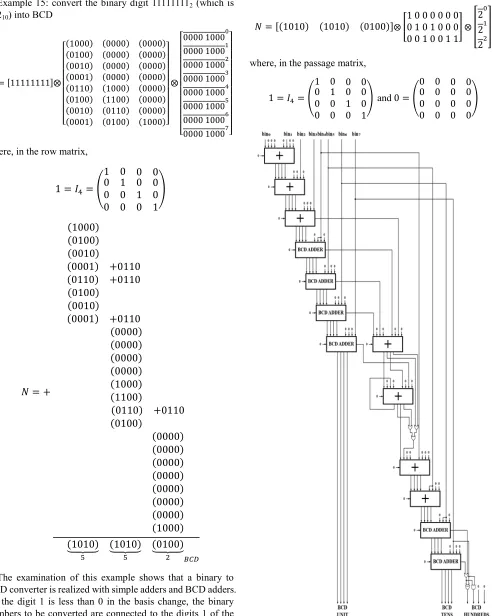
Example 15: convert the binary digit 111111112 (which is 55210) into BCD
= 11111111 ⨂
M1000N M0000N M0000N M0100N M0000N M0000N M0010N M0000N M0000N M0001N M0000N M0000N M0110N M1000N M0000N M0100N M1100N M0000N M0010N M0110N M0000N M0001N M0100N M1000N
⨂
00001000
00001000
00001000$
00001000%
00001000&
00001000:
00001000?
00001000ƒ
where, in the row matrix,
1 „& ^
1 0 0 0 0 0 0 1 0 0 0 1 0 0 0 1 a -M1000N M0100N M0010N M0001N -0110 M0110N -0110 M0100N M0010N M0001N -0110
M0000N M0000N M0000N M0000N M1000N M1100N
M0110N -0110
M0100N M0000N M0000N M0000N M0000N M0000N M0000N M0000N M1000N
M…†‡†ˆ1010N :
M1010N …†‡†ˆ
: M0100N…†‡†ˆ$ ‰Š‹
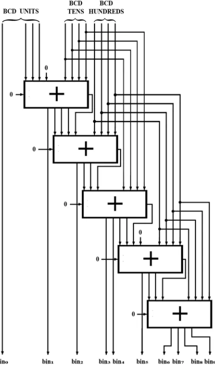
The examination of this example shows that a binary to BCD converter is realized with simple adders and BCD adders. As the digit 1 is less than 0 in the basis change, the binary numbers to be converted are connected to the digits 1 of the operands. We thus propose in figure 12 the design of a binary
converter to BCD using matrix calculation.
Example 16: (Reverse calculation): convert into binary the BCD number 1010 1010 0100BCD
M1010N M1010N M0100N⨂<10010001000000 0010011>⨂+
2 2 2$
,
where, in the passage matrix,
1 „& ^
1 0 0 0 0 0 0 1 0 0 0 1 0 0 0 1
a and0 ^
0 0 0 0 0 0 0 0 0 0 0 0 0 0 0 0 a
= +
1010 0000 0000
0000
1010
0000
0000
0000
0100
0000
1010
0000
0000
0000
0000
0000
0000
0100
0000
0000
0100
111111100$
This example shows the design of a BCD to binary converter is only made of simple adders which sum the BCD digits activated by the digits 1 in the matrix of basis change.
Figure 15. BCD to Binary Code Converter.
4. Conclusion
The utilization of matrix calculation illuminates the writing and the disposition of operations on numbers. In addition, as spoken numeration must be consistent with the writing numeration, the writing and reading of numbers have to be performed by increasing order. It supposes changes in the design of computer system. In this paper, circuits for basic arithmetic operations such as adder, subtractor, multiplier and divisor are designed and implemented in the arithmetic unit of the ALU according to the LRi writing and using matrix calculation. We propose design of code converters based on matrix calculation to convert the output code to another code such as binary to BCD code and inversely too. As the quantum computations are consistent with matrix calculations, we think that the application of these algorithms to quantum circuits is also promising.
References
[1] Raoelina Andriambololona, “Théorie générale des numérations écrite et parlée". Bull. Acad. Malg. LXIV./1-2, Antananarivo, Madagascar, 1986.
[2] Raoelina Andriambololona, "Théorie générale des numérations écrite et parlée. II Utilisation du calcul matriciel en arithmétique. Nouvelle proposition d’écriture, d’énoncé des règles d’addition et de multiplication des nombres.".Bull. Acad.Malg LXV/1-2, Antananarivo, Madagascar, 1987. [3] Raoelina Andriambololona, “Théorie générale des numérations
écrite et parlée. II- Utilisation du calcul matriciel en arithmétique. Application au changement de bases de numération. Bull. Acad. Malg. LXV./1-2, Antananarivo, Madagascar ”, 1987 (1989).
[4] Raoelina Andriambololona, Ravo Tokiniaina Ranaivoson, Wilfrid Chrysante Solofoarisina. Arithmetic and Matricial Calculation. Pure and Applied Mathematics Journal. Vol. 5, No. 3, 2016, pp. 82-86. doi: 10.11648/j.pamj.20160503.14. [5] Raoelina Andriambololona, Hanitriarivo Rakotoson “Mpikajy
elekronika sy siantifika mampiasa ny fomba fanisana Malagasy (Electronic and scientific calculator based on malagasy counting method)”, communication at the Academie Malgache, Antananarivo Madagascar, 05 June 2008.
[6] Raoelina Andriambololona, “Algèbre linéaire et multilinéaire”, Collection LIRA, INSTN-Madagascar, Antananarivo, Madagascar, 1986.
[7] Priyanka Yadav, Gaurav Kumar, Sumita Gupta, “Design and Implementation of 4-Bit Arithmetic and Logic Unit Chip with the Constraint of Power Consumption”, IOSR Journal of Electronics and Communication Engineering, 2014.
[8] M. Morris Mano, Charles Kime. “Logic and computer design fundamentals.” (4th ed.). Pearson, 2014.
[10] Deshpande Akshay, Sanidhya Mohan Sharma, Lochan Anil Vyas and K. Sivasankaran. Design of Low Power and Area Efficient 4-bit Arithmetic and Logic Unit using Nanoscale FinFET. Indian Journal of Science and Technology, Vol 8(S2), 250-256, Jan 2015. doi:10.17485/ijst/2015/v8iS2/70759. [11] Sneh Lata Murotiya, Anu Gupta. Design of CNTFET-based
2-bit ternary ALU for nanoelectronics. International Journal of Electronics. Volume 101, 2014, Pages 1244-1257.
http://dx.doi.org/10.1080/00207217.2013.828191.
[12] Garima Rawat, Khyati Rathore, Siddharth Goyal. Design and analysis of ALU: Vedic mathematics approach. International Conference on Computing, Communication & Automation (ICCCA), 2015. doi: 10.1109/CCAA.2015.7148593.