International Journal of Engineering and Management Research, Vol.-2, Issue-6, December 2012
ISSN No.: 2250-0758
Pages: 32-36
www.ijemr.net
Weight Reduction and Analysis of Trolley Axle Using Ansys
Happy Bansal1, Sunil Kumar2
1
Department of Mech. Engg., PG Mechanical student, Yadvindra College of Engineering, Talwandi Sabo, Bathinda, Punjab.
2
Department of Mech. Engg., Senior Assistant Professor, Yadvindra College of Engineering, Talwandi Sabo, Bathinda, Punjab.
ABSTRACT
In Central India, various small scale industries are adopting the crude methodologies for designing & manufacturing the machine components. One such industry producing tractor trolleys for agricultural use has been identified for this study. The existing trolley designed by the industry uses heavy axle without considering loading conditions which in turn leads to higher factor of safety increasing the overall cost of the axle. In this study, existing trolley axle is redesigned considering the static load conditions. A CAD model is prepared using ANSYS 12.0 as a tool. Improved cross section for the axle is calculated which resulted in the 11.5 % reduction in the weight of the axle. The axle dimensions are redesigned to 40 x 80 mm which is comparatively smaller than the old axle. The design is optimized based on the manufacturing cost of the axle.
Keywords—ANSYS, axle design, optimization, stress
analysis
I.
INTRODUCTION
In the present market scenario, cost reduction technique is playing a signified role to meet the competition in the market. Weight reduction and simplicity in design are application of industrial engineering etc. are used as sources of technique. Various components or products used in rural areas are mostly manufactured in small scale industries such as farming machinery, thrashers, tractor trolleys etc. It has been observed that these rural products are not properly designed. Tractor trolleys are manufactured in small to moderate scale industries. Though tractor trolleys are manufactured of various capacities by various industries, still there is a large variation in manufacturing methods, component design etc. [1]
The trolley axle is a central shaft for rotating wheels. The wheels are fixed to the axle, with bearings or bushings provided at the mounting points where the axle is supported. The axle maintains the position of the wheels relative to each other and to the vehicle body. Dead axle
does not transmit power like the front axle in a rear wheel drive is dead axle.
As this research work is based on Finite Element Analysis, so it is required that a component on which analysis is to be done should have practical application and result of experimental analysis could be compared with FE analysis results for validation. The component chosen for this purpose is dead axle of tractor-trolley which finds widespread applications in all four wheeler vehicles.
II.
STATIC LOAD ANALYSIS
The static load on axle is calculated by considering the fully loaded trolley model. The total capacity of the trolley is 60 KN but self weight of trolley and the axle assembly is 13 KN. So we consider the gross weight come over the axle is 73 KN. The trolley chassis main frame is supported at two points over the axle where the total load is divided equally as shown in the load diagram (figure 2.1) at point C & E.
Figure 2.1: Load diagram [1]
Figure 2.2: A typical Trolley & its axle visual [2] Table 2.1
Specification of 6-tonne 2-wheeler trolley [1]
General Overall Dimensions
Load
Capacity Axle Tires Single
axle
two wheeler
box type trolley
Chassis Length: 4025 mm.
Trolley box Length, width & height are 3100mm, 1900 mm & 730 mm.
Ground distance 1700 mm
Pay load: 60 KN
Unloaded Weight: 13 KN
Gross Weight: 73 KN
Square section of 75mm x75mm
& length 1700 mm
width 9”
radius 20”
III.
SHEAR FORCE AND BENDING
MOMENT ON AXLE
From load diagram, RA and RB shows the supports
or reactions provided by the tires of trolley. Load 75 kg shows the self weight of axle and (3650+3650)=7300 kg i.e. 73000 N is load of goods on trolley for which it is designed and this load is divided equally as point loads and acting on the axle as shown above in the load diagram. Now for equilibrium
Sum of upward loads = Sum of downward loads i.e. R A + RB = 36500+750+36500 = 73750 N
Now to find the reactions R A and RB , taking moment
about R A
RB x 1310 = 36500 x 1155 +750 x 655 + 36500 x 155
RB x 1310 = 48306250
RB = 48306250/1310 = 36875 N
Therefore R A = 36875 N
Calculations for Shear Forces acting on beam:
Considering R.H.S. & taking downward loads as positive and upward loads as negative
SFB = - RB = - 36875 N
SFE (up to E) = - 36875 N
SFE (at E) = - 36875 + 36500 = - 375 N
SFD (up to D) = - 375 N
SFD (at D) = -375 + 750 = 375 N
SFC (up to C) = 375 N
SFC (at C) = 375 + 36500 = 36875 N
SFA = 36875 N
Calculations for bending moments:
Considering R.H.S. & taking sagging moments as positive & hogging moments as negative.
Also as we see the axle is symmetrically loaded and Max. Bending moment will occur at centre of beam (point D). Also the Shear force changes sign from negative to positive at point D , so the Bending moment will be Maximum at point D
Mmax = MD = RB x 655 – 36500 x 500 = 5903125 N-mm
MB = RB x 0 = 0
ME = RB x 155 – 36500 x 0 = 5715625 N-mm
MC = RB x 1155 – 36500 x 1000 – 750 x 500
= 5715625 N-mm
MA = RB x 1310 – 36500 x 1155 – 750 x 655
– 36500 x 155 = 0
IV.
DESIGN OF EXISTING AXLE
A trolley axle is a stationary machine element and is used for the transmission of bending moment only. Trolley axle shaft will be designed based on its strength and subjected to bending stresses. The existing axle is a combination of hollow & square shafts as shown in the figure 4.1.
Fig. 4.1: Existing Axle
Figure 4.2: CAD Model of existing axle using ANSYS [1]
Calculations for existing design:
Volume of hollow portion = (902 – 752 ) x 1100 = 2722500 mm3
Volume of solid portion = 752 x 800 = 4500000 mm3 Total volume = 2722500 + 4500000
= 7222500 mm3 = 0.0072225 m3 Mass = density x volume= 7800 x 0.0072225 =56.4 kg As per General bending equation : M/I = σ/y
Now we will find the bending stress induced in the existing axle due to maximum bending moment of value 5903125 N-mm by using bending equation
M
max/ Imin =σ/ymax
For cross section of existing axle, ymax = 90/2 = 45 mm
And M.O.I = bd3/12 for rectangular or square sections Therefore I = 75 x 753/12
i.e. I =2636719 mm4 for solid portion & I = 90 x 903/12 - 75 x 753/12 i.e. I = 2830782 mm4 for hollow portion Thus Imin = 2636719 mm4
Therefore from bending equation 5903125/2636719 = σ /4
i.e. bending stress , σ =100.75 N/mm2 = 100.75 MPa
Which is well below the allowable bending stress 430 MPa. Hence existing axle is safe and its weight is 56.4 kg.
V.
DESIGN OF PROPOSED AXLE
In proposed design, there is 1300 mm long solid shaft of dimensions 40mm x 80mm where width of section is 40 mm and depth of section is taken as 80 mm. Further this solid shaft extends at both ends for 200 mm length of solid section 75 mm x 75 mm which would be machined for fitment into hub of trolley. The density of axle material (SAE 1045 Steel) is 7800 kg/m3. The design for proposed axle is shown in the fig. 5.1.
Figure 5.1: Proposed Design
Figure 5.2: CAD Model of proposed axle using ANSYS
Calculations for proposed design:
Volume of square portion of axle = 0.075 x 0.075 x 0.4 = 0.00225 m3
Volume of rectangular portion of axle = 0.040 x 0.080 x
1.3 = 0.00416 m3 Total volume of axle = 0.00225 + 0.00416 = 0.00641 m3
Weight of axle = Volume x Density
= 0.00641 x 7800 = 49.9 Kg
Now we will find the bending stress induced in the proposed axle due to maximum bending moment of value 5903125 N-mm by using bending equation as given here Mmax/Imin =σ/ymax
Mmax = 5903125 N-m
and Moment of Inertia ,I /12
Therefore M.O.I. for section 40 mm x 80 mm is as below I= 40 x 803/12 = 1706666.6
& for 75 x 75 section, M.O.I. is given below I = 75 X 753/12 = 2636719 mm4
Thus Imin = = 1706666.6 & ymax = 80/2 =40 mm
Therefore from bending equation, the bending stress induced in proposed axle is
5903125/1706666.6 = σ /40
i.e. σ = 138 N/mm2 or 138 MPa
Which is well below the allowable bending stress of 430 MPa. Hence the proposed design is safe under same loading conditions as the existing axle.
VI.
ANALYSIS USING ANSYS TOOL
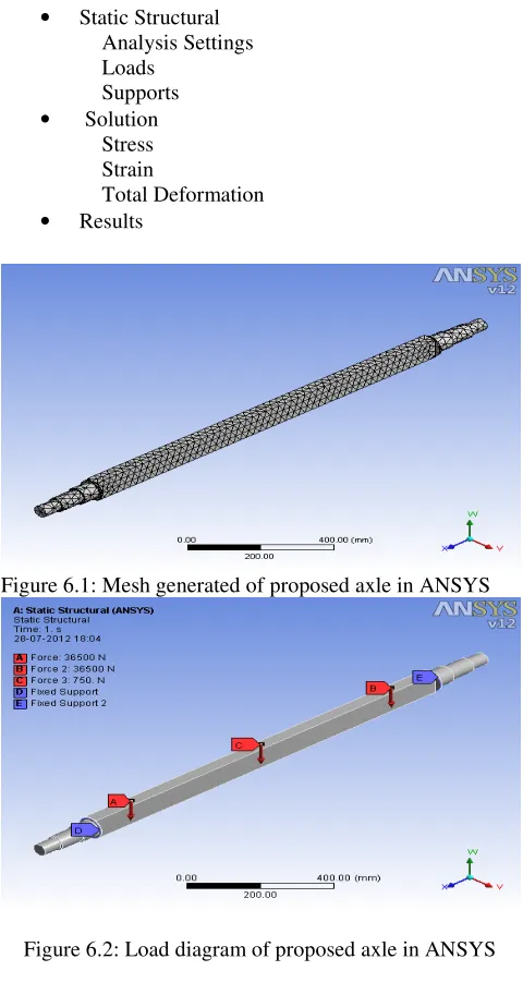
The existing axle and proposed axle geometry is generated in ANSYS 12 by selecting toolbox where various commands like draw, dimensioning, constraints, extrude, generate, rotate etc. are used. Then mesh is generated on the model and after that load points are defined and load values are given. Then the results are generated automatically for stress, strain and deformation in solution phase.
STEPS
• Model • Geometry
• Static Structural
Analysis Settings Loads
Supports • Solution
Stress Strain
Total Deformation • Results
Figure 6.1: Mesh generated of proposed axle in ANSYS
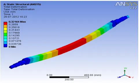
Figure 6.2: Load diagram of proposed axle in ANSYS
Figure 6.3: Stress in existing axle
Figure 6.4: Stress in proposed axle
Figure 6.5: Equivalent strain in existing axle
Figure 6.6: Equivalent strain in proposed axle
Figure 6.8: Deformation in proposed axle
The proposed axle is analysed for the same loading values and same load point locations as the existing axle. The material selected for the proposed axle is same as for existing axle which is SAE 1045. This steel is ideal for shafts, axles, sprockets and other machine parts requiring better strength than 1020 mild steel. The density of SAE 1045 Steel is 7800 kg/mm3 and allowable bending stress is 430 MPa.
The red colour shows the maximum and blue colour shows the minimum values for stress, equivalent strain and total deformation in the existing axle and in proposed axle.
VII. CONCLUSION
No doubt the existing Combination axle is safe under the given loading conditions but it involves some problems. It is difficult to manufacture such a design as it needs one hollow shaft and two solid shafts which are inserted into hollow shaft at both ends and then welded for rigidity. A welded joint may fail for prolonged use and on rough roads. It also includes manufacturing difficulties as it is much difficult to fabricate or cast a hollow shaft than a solid shaft.
The newly designed axle eliminates such problems as it is solid in all. The proposed axle takes less time to produce, so higher production rate is achieved. Further the total weight of combination axle is 56.4 Kg whereas in proposed design it comes to be 49.9 Kg. Thus 11.5% reduction in weight is achieved, which results in reduced cost.
Table7.1
Comparison between existing and proposed axle
S.No. Existing Axle Proposed Axle
1. Material: SAE 1045 Material : SAE 1045
2.
Minimum Section Modulus : 58.5x103 mm3
Minimum Section Modulus : 42.6x103 mm3 3. Allowable Bending
Stress : 430 MPa
Allowable Bending Stress: 430 MPa
4. Bending Stress induced : 100 MPa
Bending Stress induced : 138 MPa
5. Bending Stress calculated by ANSYS =104.63 MPa
Bending Stress calculated by ANSYS =138.99 MPa
6. Equivalent Strain = 0.000523
Equivalent Strain = 0.00069
7. Total Deformation = 0.090157 mm
Total Deformation = 0.321 mm
8.
Weight of Hollow shaft =22.4 Kg & Weight of Solid Shaft= 34 Kg Total Weight= 56.4Kg
Total Weight 49.9 kg
REFERENCES
[1] H. V. Katore, S. B. Jaju, “Redesigning of Tractor-Trolley Axle using ANSYS,” International Journal of Engineering Science and Technology (IJEST), vol.3, pp. 4702-4710, June 2011.
[2] http://en.wikipedia.org
[3] N. Leon, P.O. Martinez, and P. Adaya, “ Reducing the Weight of a Frontal Axle Beam Using Experimental Test Procedures to Fine Tune FEA,” 2nd Worldwide MSC Automotive Conference, Dearborn, Michigan, pp. 1-14, October 2000.
[4] O. Asi, “Fatigue failure of a rear axle shaft of an automobile,” Engineering Failure Analysis 13, pp. 1293–1302, February 2006.
[5] A. P. Birnale, D.R. Milagi, K. S. Mali, “ Shape optimization of front axle,” Altair CAE user conference Bangalore, pp. 1-7, August 2006.
[6] C. Y. Lin, J. P. Hung, T. C. Hsu , “Failure Analysis of Reverse Shaft in the Transmission System of All-Terrain Vehicles,” ASM International, pp. 75-80, January 2008.
[7] A. Jafari, M. Khanali, H. Mobli, A. Rajabipour, “Stress Analysis of Front Axle of JD 955 Combine Harvester Under Static Loading,” Journal of Agriculture & Social Sciences, vol. 8, pp. 359-364, March 2010.
[8] M.R. Khoshravan, A. Paykani, A. Akbarzadeh, “Design and Modal Analysis of Composite Drive Shaft for Automotive Application,” International Journal of Engineering Science and Technology (IJEST), vol.3, pp. 2543-2549, April 2011.
![Figure 2.1: Load diagram [1]](https://thumb-us.123doks.com/thumbv2/123dok_us/9789666.1964629/1.612.328.562.532.633/figure-load-diagram.webp)
![Figure 4.1: Existing axle [1]](https://thumb-us.123doks.com/thumbv2/123dok_us/9789666.1964629/2.612.322.565.488.734/figure-existing-axle.webp)
![Figure 4.2: CAD Model of existing axle using ANSYS [1]](https://thumb-us.123doks.com/thumbv2/123dok_us/9789666.1964629/3.612.324.563.50.188/figure-cad-model-existing-axle-using-ansys.webp)