Performance Analysis of LMS Filter Using Barker and Chaotic Sequences
for Radar Target Detection
Jami Venkata Suman
*Department of ECE, GMR Institute of Technology, Rajam, India.
Received 05 September 2017; received in revised form 24 October 2017; accepted 17 November 2017
Abstract
Target detection and tracking play a very foremost role in space and underwater scenario. In this paper , we presented a new Least Mean Square based Radar Target Detection (LMS-RTD) model is proposed to de-noising of continuous wave radar transmitted signal. In target detection, radio frequency (RF) energy is transmitted to and reflected from the reflecting object which has a status of target information. Signal generation and target detection of Radar model is designed and simulated using MATLAB 2017a Simulink. The study of performance analysis of signal generation model using binary chaos phase sequences using different chaotic maps, barker codes, combined barker code sequences and the de-noising algorithm using adaptive LMS filter is also presented in this paper. Implementation of an adaptive LMS filter using Verilog HDL and its analyses using Xilinx FPGA tool. In FPGA analysis, number of LUT’s and used flip flops are improved in proposed LMS-RTD method than conventional methods .
Keywords: RADAR, chaotic maps, barker codes, MATLAB Simulink, LMS-RTD, Xilinx FPGA, RMSE
1. Introduction
In recent days, Radio Detection and Ranging (RADAR) has a major significance in the object detection and tracking in space applications. Radar is a system used for detecting the presence, direction, distance, and speed of aircraft, ships and other objects by sending out pulses of high frequency electromagnetic waves that are reflected off the object back to the source. Mainly it refers to the technique of using radio waves to detect the presence of objects in the atmosphere. The radar signal de-noising is the key function in target detection and target tracking systems. LMS algorithm adjusts the filter coefficients to minimize the cost function. It is a class of adaptive filter used to mimic a desired filter by finding the filter coefficients that reveal to producing the least mean square of the error signal. Stanford University professor Bernard Widrow has invented this LMS algorithm in 1960. It is a stochastic gradient descent method in that the filter is only adapted based on the error at current time. The block diagram of adaptive LMS filter is shown in Fig. 1.
Fig.1 Block diagram of adaptive LMS filter
where x(n)=input digital signal, y(n)=output digital signal, d(n)=desired response and ye(n)= estimation error or error signal.
Eventually result can write in the form of three basic relations as follows : (1) Filter output:
y(n)
w(n) * u(n)
(1)(2) Estimation error or error signal: e
y (n)
d(n)
y(n)
(2)(3) Tap weight adaptation:
e
w(n+1)
w(n)
mu *u(n) y *(n)
(3)In our surroundings , we have different kinds of signals such as natural, man -made, audio, video, speech, image, communication, geophysical, sonar, radar, medical and musical signals, while many are unwanted signals in a given situation. Anything that carries information is a signal and an engineering contest is a function that “conveys information about the behaviour or attributes of some phenomena” and these signals might be necessary or unwanted that depends at that s ituation. Signal processing is an operation meant for extracting, enhancing, storing, and transmitting useful information. Hence it ten ds to be application dependent. Adaptive filters are used in which we don’t have constant filter coefficients and no prio r information is known to us compared to conventional filters.
Chaos theory is a field of mathematics focused on the non linear deterministic dynamical systems behaviour. Chaos is highly sensitive to initial conditions . This effect is popularly referred to as the butterfly effect. It is having applications in several disciplines including physics, engineering, economics, biology and philosophy. A very small disturbance in initial condition produces a drastically different final solution for the chaotic system and the long-term prediction is impossible. This happens even though these systems are deterministic, meaning that their future behaviour is fully determined by their initial conditions, with no random elements involved in this process. This behavior is known as deterministic chaos, or simply chaos [1]. A chaotic dynamical system is deterministic, bounded system that exhibits randomness behavior through its initial sensitive conditions. Since, in practice initial conditions can never be specified with infinite precision. The random Chaos sequences can be generated using various logistic, improved logistic, tent, cubic and quadratic chaotic maps [3-8]. In this paper an attempt is made to generate binary sequences using these maps and their properties at different lengths are studied for improving the performance of radar target detection.Pitchaiah proposed the high-speed Implementation of Distributed Arithmetic (DA) based architecture for adaptive LMS filter. It is not given precious results because of the required time and hardware complexity [9].
2. LMS - RTD Methodology
In the recent days moving target(s) detection and tracking have become challenging. To increase the accuracy of the target detection in the free space environment, we have implemented an efficient de-noising algorithm in this LMS–RTD method. In order to de-noise the signal, an algorithm is applied to the received noisy signal so that it can suppress the color noise, which is affected due to environmental disturbances occurred in the free space. The target detection efficiency is directly proportional to the de-noising algorithm efficiency. In this paper, Matlab 2017a Simulink is used to model the RADAR transceiver and free space environment. The implementation of De-noising algorithm used for the LMS is done by using Verilog-HDL and it is synthesized by using Xilinx FPGA tool.
quadratic, cubic and tent maps. These barker codes have various lengths such as 2, 3, 4, 5, 7, 11 and 13. For improving the radar target detection performance and increase the efficiency of operation, binary chaotic phase and barker sequences are used to modulate the sine wave.
Fig.2 Block diagram of the proposed LMS-RTD methodology
The block diagram proposed method consists of the Radio Frequency section, switch, antenna, received signal, LMS filter, convolution, and display. In this method, the modulator send s the sinusoidal signal through the RF section and then after over the antenna. As shown in fig. 2 the transmitter sends the Radio signal through the antenna and then it is pas sed through the free space for detecting object(s). The radar pulse with high velocity has to hit the target and it is reflected back. Depending o n the echo signal velocity, object velocity and its position from the base station are detected. The environme ntal disturbances are the cause for the suppression of the signal and this can be rectified by using adaptive LMS filter. After the filtering process t he detected object parameters are processed, then analyzed according to that the position will be determined.
3. Signal Generation
3.1 Binary phase code generation using chaotic maps
A Chaotic dynamical system is a bounded, deterministic system that exhibits random-like behavior through its sensitive dependence on its initial conditions. The use of chaotic s ignals in radar has received a lot of attention in the recent years because they behave like noise, have a wide band and are easy to generate. In mathematics, a chaotic map is a map (= evolution function) that exhibits some sort of chaotic behavior. Maps may be parameterized by a discrete-time or a continuous -time parameter. Discrete maps usually take the form of iterated functions . Chaotic maps often occur in the study of dynamical systems .
Chaotic maps often generate fractals. Although a fractal may be constructed by an iterative procedure, some fractals are studied in and of themselves, as sets rather than in terms of the map that generates them. This is often because there are several different iterative procedures to generate the same fractal. Since, in practice init ial conditions can never be specified with infinite precision, the behavior of a chaotic system is unpredictable and therefore noise like. Chaotic Sequences can be generated using different types of chaotic maps. Some of the maps are
a)Logistic map
b)Improved logistic map c)Cubic map
3.1.1. Logistic map
The logistic map is a polynomial mapping (equivalently, recurrence relation) of degree 2, often cited as an archetypal example of how complex, chaotic behavior can arise from very simple non-linear dynamical equations.As a part of discrete-time demographic model this logistic map was popularized in a seminar 1976 paper by the biologist Robert May and this map is analogous to the logistic equation first created by Pierre François Verhulst. Mathematically, the logistic map is written:
x(n+1)
f * x(n)
* x(n)*(1 x (n))
µ
(4) where µ is constant and is called the bifurcation parameter [μ € (0, 4)] and [x € (0, 1)]. The behavior depends on the value of μ in the equation. When μ = 4 the logistic map exhibits chaotic behavior.3.1.2. Improved logistic map
This map described by the equation.
2
x(n+1)
f * x(n) 1 2* x (n)
(5)where x € (-1, 1)
This equation shows the chaotic behavior of initial value x(0) varying from 0 to 1. When x (0) > 1 as n tends to infinity, x(n) also tends to infinite.
3.1.3. Cubic map
This map described by the equation.
3
x(n+1)
f * x(n)
* x (n)
3* x(n)
(6)where x € (-1, 1) and µ=4
3.1.4. Tent map
Tent maps are widely used for chaos based applications because it is a discrete -time piecewise-affine Input/Output characteristics curve, such as true random number generation. This map described by the equation.
3
x(n+1)
f * x(n)
* x (n) [1 2 | x(n) 0.5]
(7)3.1.5. Quadratic map
This map is described by the following equation .
2
x(n+1)
f * x(n)
0.5
* x(n)
(8)where x(n) ∈ (−1, 1) and µ =4
3.2. Binary phase code generation using bark er and combined bark er codes Table 1 Barker codes
No of panels Barker code
2 +1 -1
2 +1 +1
3 +1 +1 -1 4 +1 +1-1 +1 4 +1 +1+1 -1 5 +1 +1 +1 -1 +1 7 +1 +1 +1 -1 -1 +1 -1
The known nine barker codes are represented in Table 1. Combined barker code method involves phase coding with one Barker code within each segment of another Barker code. For example, the Barker code of length 3, B3, may be combined with that
of length 4, B4, to create a code of length 12: B43=B4⊗B3= (+1 +1-1 +1, +1 +1-1 +1, -1 -1 +1 -1). Note that Bnm=Bn⊗Bm is the
Kronecker product. Note that Bnn is not used because partial correlations are high [10].
4. Implementation of Proposed Method
The proposed method was designed and simulated in MATLAB R2017a Simulink to obtain the de-noised signal by using adaptive LMS filter. Xilinx ISE tool is used to find the number of Flip -flops, slices and LUTs. A number of iterations were performed to de-noising radar signal and to obtain the minimized values of RMSE and better values of SNR.
5. Results and Discussion
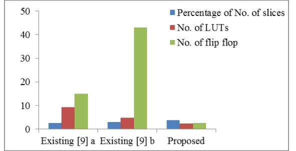
The Table 2 is the performance of the parameters such as number of slice, LUTs and flip flops for LMS method. From this result table, we can easily understand that the nu mber of LUTs and flip-flop’s can be reduced in proposed LMS method. Due to the reduction of those parameters, the area can be optimized in LMS filter. The LMS performance is shown in Fig. 3, which is getting from Xilinx ISE software.
Table 2 Number of slices, LUTs, flips flops for LMS algorithm using Xilinx ISE FPGA Tool
Filter order Algorithms No. of slices No. of LUTs No. of flip flop
16 - tap [9] a 732/28800 2714/28800 449/2997 16 - tap [9] b 888/28800 1376/28800 681/1583 8 - tap LMS 208/5,472 272/10,944 288/10,944
The Fig. 3 shows the hardware performance of LMS method. It described the total number of used LUTs, slice and flip flop values of the proposed LMS and existing methods. Furthermore, the proposed LMS method reduces number of LUTs and flip flop as compared with existing algorithms.
Fig. 3 Performance of slices, LUTs and flip flop for different algorithms using bar graph
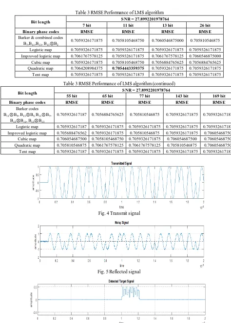
The Table 3 shows the study of performance analysis of RMSE values using LMS algorithm for different phase code sequences. As discussed earlier, the entire system is modelled by using MATLAB Simulink environment. The Simulink provides customizable block libraries, a graphical editor, and solvers for simulating and modelling dynamic systems .
filter). In this paper, the modulator will send the signal through the selector after this radar signal over the target as sh own in the Fig. 7. It is transmitted towards the target to detect objects which are in space. The radar pulse with high velocity has hit to targ et and it is reflected back.
Table3 RMSE Performance of LMS algorithm
Bit length S NR = 27.8992201978764
7 bit 11 bit 13 bit 26 bit
Binary phase codes RMS E RMS E RMS E RMS E
Barker & combined codes B7,B11,B13, B13⊗B2
0.7059326171875 0.7058105468750 0.7060546875000 0.705810546875
Logistic map 0.7059326171875 0.7059326171875 0.7059326171875 0.7059326171875 Improved logistic map 0.7061767578125 0.7059326171875 0.7061767578125 0.7060546875000 Cubic map 0.7059326171875 0.7058105468750 0.7056884765625 0.7056884765625 Quadratic map 0.7064208984375 0.7054443359375 0.7059326171875 0.7059326171875 Tent map 0.7059326171875 0.7059326171875 0.7059326171875 0.7059326171875
Table 3 RMSE Performance of LMS algorithm (continued)
Bit length S NR = 27.8992201978764
55 bit 65 bit 77 bit 143 bit 169 bit
Binary phase codes RMS E RMS E RMS E RMS E RMS E
Barker codes B11⊗B5, B13⊗B5, B11⊗B7,
B13⊗B11, B13⊗B13
0.705932617187 0.7056884765625 0.705810546875 0.7059326171875 0.7059326171875
Logistic map 0.705932617187 0.7059326171875 0.7059326171875 0.7059326171875 0.7059326171875 Improved logistic map 0.705688476562 0.7059326171875 0.705810546875 0.7059326171875 0.706054687500
Cubic map 0.706054687500 0.7058105468750 0.7059326171875 0.706054687500 0.706054687500 Quadratic map 0.705810546875 0.7061767578125 0.7061767578125 0.705810546875 0.706054687500 Tent map 0.705932617187 0.7059326171875 0.7059326171875 0.7059326171875 0.7059326171875
Fig. 4 Transmit signal
Fig. 5 Reflected signal
Depending on the reflected or received signals velocity, target velocity from the base station ca n be measured. Finally, the detected object parameters are processed, analyzed of the target and motion will be determined. The Fig. 4 shows the modulated sine wave sequence which is used to transmit towards the target with respect to time. Fig. 5 shows the noisy signal which is affected by additive white Gaussian noise. Fig. 6 shows the detected target location in terms of distance from transmitter the transmitter..
The RTL schematic of LMS filter is shown in Fig. 8. This schematic obtained from Simplify pro by using Verilog HDL code which is written for LMS.
Fig. 7 Proposed target detection tracking model using MATLAB Simulink
6. Conclusions
This paper presented a new efficient radar target detection using radar signal de-noising with an LMS to suppress the noise which is added in free space. In order to validate the proposed LMS-RTD design with existing designs, RMSE and SNR values are evaluated by using MATLAB Simulink, number of slices, LUTs and flip-flops are evaluated using Xilinx ISE FPGA tool. From the Matlab Simulation results, I concluded that the 7 bit binary chaotic quadratic phase code sequences is giving best RMSE value as compared with barker codes and combined barker codes. From Xilinx ISE FPGA simu lation results, proposed model details were estimated more precisely than other existing models with less hardware and computational complexity
References
[1] R. L. Devaney, A first course in chaotic dynamical systems: Theory and experiment (Studies in Nonline arity), Westview Press, 1992.
[2] V. JaganNaveen, T. Prabakar , J. V. Suman, and P. D. Pradeep, “Noise suppression in speech signals using adaptive algorithms,” International Journal of Signal Processing, Image Processing and Pattern Recognition, vol. 3, no. 3, pp. 87-96, September 2010.
[3] J. B. Seventline, D. E. Rani, and K. R. Rajeswari, “Ternary chaotic pulse compression sequences,” Radioengineering, vol. 19, no. 3, pp. 415-420, 2010.
[4] K. Sridevi, J. B. Seventline, and D. E. Rani, “Four phase pulse compression sequences generated using chaotic maps,” International Journal of Computer Applications, vol. 48, no. 14, pp. 25-30, June 2012.
[5] B. N. Mahaseth and M. S. Anuradha, “Binary and ternary sequence generation using improved logistic map,” International Journal of Advanced Research in Computer and Communication Engineering, vol. 2, no. 8, pp. 3290-3294, August 2013. [6] A. Ashtari, G. Thomas , H. Garces, and B. C. Flores, “Radar signal design using chaotic signals”, Proc. International
Waveform Design And Diversity Conference, pp. 353-357, October 2007.
[7] G. Heidari-Bateni and C. D. Mcgillen, “Chaotic sequences for spread spectrum: An alternative to PN-Sequences”, IEEE Conference on ICSTWC, pp. 437-440, 1992.
[8] R. C. Hilborn, “Chaos and nonlinear dynamics: an introduction for scientists and engineers,” Canada: Oxford University Press, 1994.
[9] T. Pitchaiah and P. V. Sridevi, “Low power area efficient high speed implementation of lms adaptive filter using distributed arithmetic”, International Journal of Emerging Trends in Electrical and Electronics, vol. 11, no. 4, pp. 69-75, 2015.