Copyright © 2013 IJECCE, All right reserved
Identi
fication
of Optimal Operating Point Of PV
Modules Using Fuzzy Logic Control
Hadi nabizadeh
Faculty of Electrical Engg.,Malek-Ashtar University of Technology
(MUT) Tehran, Iran [email protected]
Mohammad Reza
Alizadeh Pahlavani
Faculty of electrical Engg. Malek-Ashtar University ofTechnology (MUT), Tehran, Iran [email protected]
Ahmad Afifi
Faculty of electrical Engineering, Malek-AshtarUniversity of Technology (MUT), Tehran, Iran
Iman Soltani
Faculty of Electrical Engg., Malek-Ashtar University ofTechnology (MUT) Tehran, Iran i_soltani@ ikiu.ac.ir
Abstract – This paper introduces an intelligent control method for maximum power point tracking in solar array in dealing with the rapid variations in temperature and radiation. Fuzzy logic controller and DC/DC boost converter are the most important components of this system. The simulation results of fuzzy logic controller are compared with simulation results of PI controller in both cases without noise and with Gaussian noise in solar cell voltage. The results show that fuzzy logic controller performance is better than PI controller especially in the presence of noise.
Keywords–Maximum Power Point Tracking, Photovoltaic System, Fuzzy Logic, DC/DC Boost Converter.
I. I
NTRODUCTIONBecause of energy crisis and environmental issues such as pollution and global warming, the use of photovoltaic system is a very good solution to solve this problems. Unfortunately the energy conversion efficiency of photovoltaic modules is relatively low. So to overcome this problem and obtain possible maximum efficiency, all designed elements of photovoltaic system such as MPPT controller must be optimized to increase efficiency[1]. MPPT controllers are an essential component of photovoltaic system. These controllers can be used in simple techniques such as voltage and current feedback methods or can be used in more efficient algorithms such as perturb and observation (P&O) and incremental conductance. In recent years the intelligent maximum power point tracking such as neural networks, fuzzy logic algorithms are used[2]. Perturb and Observe, incremental conductance and fuzzy logic algorithms are common MPPT methods. Perturb and observe and incremental conductance have disadvantages such as losing maximum power point tracking in rapid variation of radiation and temperature and fluctuations of voltage and current around the maximum power point tracking at steady state[3], While fuzzy logic algorithm has good performance in rapid changes of temperature and radiation and less fluctuation around its maximum power point tracking at steady state[4]. Therefore, in this paper, the intelligent MPPT controller based on fuzzy logic is used to increase the efficiency of photovoltaic system.
II. P
RINCIPLES OFM
AXIMUMP
OWERP
OINTT
RACKINGThe equivalent circuit of solar cell which consists of a photo current, a diode, a parallel resistor expressing a leakage current, and a series resistor describing an internal resistance to the current flow, is shown in "Figure 1". The voltage-current characteristic equation of a solar cell is given as
( )
exp S 1 S
ph sat
Sh
q V IR V IR
I I I
kTA R
(1)
Where,
I
ph is a light-generated current or photocurrent,sat
I
is the cell saturation of dark current,q
(= 1.6 ×10⁻¹⁹C) is an electron charge,
k
(= 1.38 ×10⁻²³J/K) is the Boltzmann’s constant,T
is the cell’s workingtemperature,
A
is an ideal factor,R
Sh is a Shunt resistance andR
S is a series resistance of solar cell.DC
R
SR
ShI
V
+
-I
PhI
DFig.1. Solar cell model
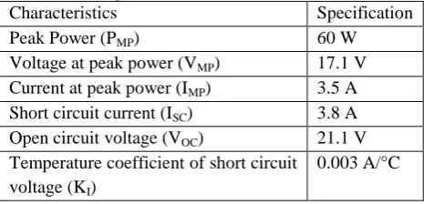
The specifications (at 1kW/m2, 25˚C) of the solar
module used for simulation is given in "Table 1". Table 1: Specification of the simulated module
Specification Characteristics
60 W Peak Power (PMP)
17.1 V Voltage at peak power (VMP)
3.5 A Current at peak power (IMP)
3.8 A Short circuit current (ISC)
21.1 V Open circuit voltage (VOC)
0.003 A/°C Temperature coefficient of short circuit
Simulation results of photovoltaic module for Power –
Voltage characteristic are shown in "Figure 2" and "Figure 3" for temperature and radiation changes. The photovoltaic module operation depends strongly on its operating voltage.
For a specific temperature and radiation, the maximum output power occurs at a particular voltage called maximum power point[5]. So if the load is directly connected to a photovoltaic module, photovoltaic module output is rarely maximized and operating point is not optimal.
Fig.2. Power–voltage characteristic of photovoltaic module for different working temperature at 1[KW/m2]
radiation
Fig.3. power–voltage characteristic of photovoltaic module for different working radiation at 27 [°C]
temperature.
To solve this problem, using a DC/DC boost converter with MPPT controller between photovoltaic module and load is required[6]. general block diagram of PV module with MPPT system is shown in "Figure 4".
Figure4: General block diagram of the MPPT sytem Schematic of maximum power point tracking system in Matlab/ Simulink environment is shown in "Figure 6". In the last decade many techniques have been proposed for tracking maximum power point. These techniques can be classified in three categories[7]:
Voltage feedback based methods which compare the photovoltaic operating voltage with a reference voltage in order to generate the PWM control signal of the DC/DC converter.
Current feedback based methods which use photovoltaic short circuit current as a feedback in order to estimate the optimal current corresponding to the maximum power.
Power based methods which are based on iterative algorithms to track continuously the MPP through the current and voltage measurement of the photovoltaic module.
III. F
UZZYL
OGICM
AXIMUMP
OWERP
OINTT
RACKINGC
ONTROLLERFuzzy logic maximum power point tracking has the advantages of simple design and do not require the knowledge of exact model. Instead, these controllers require full information about the performance of photovoltaic system. The proposed fuzzy logic controller is shown "Figure 5", which has two input and one output[8].
Copyright © 2013 IJECCE, All right reserved
Fig.6. Schematic of maximum power point tracking system in Matlab / Simulink environment. The two input variables are error (E) and change of
error (CE) at sampled times k defined by:
(2)
( )
(
1)
( )
( )
(
1)
P k
P k
E k
V k
V k
(3)
( )
( )
(
1)
CE k
E k
E k
Where P(k) and V(k) are generated power and voltage of photovoltaic module respectively. The input E(k) show that operating point at the instant k is located on the left or on the right of the maximum power point tracking, while input CE(k) indicates the moving direction of this point[9].
For fuzzy inference Mamdani’s method is used, and for
defuzzification the center of gravity to compute the output of controller is used which is the duty cycle:
(4)
1 1 n j j j n j j D D D D
The used rule bases of fuzzy controller are shown in "Table 2" with E and CE as inputs and D as the output.
Table 2: Fuzzy rule table
PB PS ZE NS NB CE E ZE NS NS NB NB NB PS ZE NS NS NB NS PB PS ZE NS NB ZE PB PS PS ZE NS PS PB PB PB PS ZE PB
The designed Membership functions for two inputs and one output as duty cycle are shown in "Figure 7".
Fig.7. Membership functions of error, change of error and duty cycle.
Gain of Noise
1
Discrete, Ts = 2.5e-006 s.
powergui v + -v + -v + -sawtooth ioutf Poutf ipvf pulse controlf vpvf powerf1 powerf voutf P_k V_k e de Subsystem1 temperature solar insolation Voltage1 current power Subsystem g m D S [P] [A] Gaussian Gaussian Noise Generator -K-1 1 Fuzzy Logic Controller [P] [A] u m fs signal out fcn i +-i +-s -+ 1 frequency 300 ... Signal 1 290--330 Signal 1
IV. S
IMULATION RESULTS OFMPPT
CONTROLLER WITH
F
UZZY ANDPI
CONTROLLERS
The general diagram simulation of photovoltaic system is shown in "Figure 5". The DC/DC converter is a boost chopper. The PI and fuzzy MPPT controllers under following conditions are simulated and tested.
Rapid changes of radiation from 0.5[KW/m2] to 1[KW/m2] at 27[°C] constant temperature without applying noise to system.
Rapid changes of radiation from 0.5[KW/m2] to 1[KW/m2] at 27[°C] constant temperature and with applying gaussian noise with variance of 0.5 on the photovoltaic module voltage.
Rapid changes of temperature from 17 [°C] to 47 [°C] at 1[KW/m2] constant radiation without applying noise to system.
Rapid changes of temperature from 17 [°C] to 47 [°C] at 1[KW/m2] constant radiation with applying gaussian noise with variance of 0.5 on the photovoltaic module voltage.
Fig.8. Output power of solar module and control signal for both PI and Fuzzy controllers for rapid changes of radiation from 0.5[KW/m2] to 1[KW/m2] at constant
temperature 27[°C] without applying noise. The following figures show the results of these tests. In these figures, the output power of photovoltaic module and control signal (duty cycle of converter) for both PI and Fuzzy controllers for expression changes are shown. Output power of photovoltaic module and control signal for rapid changes of radiation from 0.5[KW/m2] to 1[KW/m2] at 27[°C] constant temperature without applying noise and with applying noise on the photovoltaic module voltage for both PI and Fuzzy MPPT controllers are shown In "Figure 8 " and "Figure 9 ".
And output power of photovoltaic module and control signal for rapid changes of temperature from 17 [°C] to 47 [°C] at 1[KW/m2] constant radiation without applying noise and with applying gaussian noise on the photovoltaic module voltage for both PI and Fuzzy MPPT controllers are shown in "Figure 10" and "Figure 11".
Fig.9. Output power of solar module and control signal for both PI and Fuzzy controllers for rapid changes of radiation from 0.5[KW/m2] to 1[KW/m2] at constant temperature 27[°C] with applying gaussian noise with
variance 0.5 on the photovoltaic module voltage.
Fig.10. Output power of solar module and control signal for both PI and Fuzzy controllers for rapid changes of temperature from 17 [°C] to 47 [°C] at constant radiation
1[KW/m2] without applying noise.
Copyright © 2013 IJECCE, All right reserved Output power of photovoltaic module for PI and Fuzzy
controllers at three different sample points of temperature and radiation changes while applying gaussian noise to photovoltaic module are shown in "Table 3" and "Table 4".
Table 3: Output power of PV module versus different sample of temperature amounts while applying gaussian
noise, G=1000 T
(°C)
Real value
PI controller
Fuzzy controller
Accuracy (%)
17 63 49 51 81.06
32 55 30 48 87.27
47 48 40 41.5 86.45
Table 4: Output power of PV module versus different sample of radiation amounts while applying gaussian
noise, T=27 G(KW/m2) Real
value
PI controller
Fuzzy controller
Accuracy (%)
0.5 33 22 27 82.35
0.75 45 30 38 84.44
1 60 50.5 51.1 85.16
Results show that Fuzzy controller has better performance specially with applying noise on photovoltaic module voltage compared with PI controller.
V. C
ONCLUSIONSPurpose of this paper is tracking maximum power point of photovoltaic module by Fuzzy logic controller for temperature and radiation changes and comparing results with PI controller.
Simulation results show that Fuzzy controller has higher convergence rate at tracking maximum power point compared with PI controller.
Also, with the presence of noise on output voltage of photovoltaic module, the Fuzzy controller performs much better than PI controller at transient conditions of temperature and radiation. So the Fuzzy controller can be very good performance compared with common controllers for non-linear systems. Since Fuzzy controller is extremely flexible might elaborate on the importance of the work or suggest applications and extensions.
R
EFERENCES[1] D.S.Morales, “Maximum Power Point Tracking Algorithms for Photovoltaic Applications”, Thesis submitted for examination for the degree of Master of Science in Thechnology. Espoo 14.12.2010.
[2] T.Esram, P.L.Chapman, “Comparison of Photovoltaic Array Maximum power point Tracking Techniques”IEEE Transactions On Energy Conversion, VOL.22,NO.2,June 2007.
[3] N.Femia,D.Granozio,G.Petrone, M.Vitelli,“Predictive & Adaptive MPPT Perturb and Observe Method” IEEE TRANSACTIONS ON AEROSPACE AND ELECTRONIC SYSTEMS VOL. 43, NO. 3 JULY 2007.
[4] P.Takun,S.Kaitwanidvilai,C.Jettanasen, “Maximum Power Point Tracking using Fuzzy LogicControl for Photovoltaic System” Proceedings of International MultiConference of Engineers and Computer Scientists 2011 Vol II, IMECS 2011, March 16-18,2011,Hong Kong.
[5] S.Panwar,R.PSaini, “Development and Simulation of Solar Photovoltaic model using Matlab/simulink and its parameter extraction”, International Conference on Computing and Control Engineering(ICCCE 2012) , 12 & 13 April, 2012.
[6] P.A.Lynn, Electricity from Sunlight: An Introduction to Photovoltaics, John Wiley & Sons, 2010, p.238.
[7] M.S. Aït Cheikh*, C. Larbes†, G.F. Tchoketch Kebir and A. Zerguerras, “Maximum power point tracking using a fuzzy logic control scheme”,Revue des Energies Renouvelables Vol. 10 N°3 (2007) 387–395.
[8] G. Balasubramanian, S. Singaravelu, “ Fuzzy logic controller for the maximum power point tracking in photovoltaic system”, International Journal of Computer Applications (0975–8887) , Volume 41–No.12, March 2012 .
[9] Chung Won,Duk Kim,Sei Kim,Won Kim,Hack Kim, “A New Maximum Power Point Tracker of Photovoltaic Array Using Fuzzy Controller” Kyung Ki DO,#440-746 Seol,Korea, 1994 IEEE.
A
UTHOR’
SP
ROFILEMr. Hadi Nabizadeh
received his Bachelor in Electronic Engineering in 2010 from the University of Tabriz, Iran. he is an M.Sc student of electrical engineering at Malek-Ashtar University (MUT). His research interests include all areas of power electronics, renewable energy, intelligent control, nonlinear systems control and micro- and nanoelectronic.
Mohammad Reza Alizadeh Pahlavani
received his degree in electrical engineering from Iran University of Science and Technology (IUST) in 2009. He is the author of more than 125 journal and conference papers in field of electromagnetic systems, electrical machines, power electronic, FACTS devices, and pulsed power. Malek- Ashtar University of technology (MUT), Shabanlo St., Lavizan, Tehran, Iran. Email: [email protected]
A. Afifi
received the B.S. degree in electrical engineering from Kashan University in 1998 and M.S. degree from Iran University of Science and Technology (IUST) in 2000, where he is currently working toward the Ph.D. degree in electrical engineering. His current research interests include micro- and nanoelectronic circuits, intelligent signal-processing and bio-inspired computational models.
Mr. Iman Soltani
received his Bachelor in Robotic Engineering in 2011 from the University of Shahrood,Iran.he is an M.Sc student of electrical engineering at Imam Khomeini Internatial University (IKIU). He has been working on several research and consulting projects in the area of powered converters. His research interests include all areas of power electronics, renewable energy, power electronics , machine control, intelligent control, nonlinear systems control and optimization techniques such as, particle swarm optimization (PSO) and differential evolution(DE).