Volume 02, No. 4, April 2016
P
age
90
An Alternative Approach of Binary Optical Data Addition
Scheme with Modified Trinary Number (MTN) System
Partha Pratim Das
Department of Applied Science, Haldia Institute of Technology, HIT, Haldia Purba Medinipur, West Bengal, India
ABSTRACT
An alternative optical scheme is proposed here for bit-wise data addition with the proper exploitation of modified trinary number system. The scheme is carry-lees approach and thus perfectly suitable in parallel processing in optical domain.
Key Words:Binary, Data addition, modified trinary number, parallel processing.
1. INTRODUCTION
Since last five decades there were lot of schemes proposed by the scientists, researchers and technologists in the globe for conducting carry-less arithmetic data addition and subtraction processes. These processes are performed with different conceptual approaches. Some of
these are done with the introduction of signed digit symbolic substitution.1, 6, 7 In such
connection we can mention a proposal of an all-optical methodology for bit-wise binary data
subtraction. 6 This method of the subtraction is done between two binary data, one is minuend
and another is subtrahend. For bit to bit subtraction (between the any two bits) coming from the two data, only the possibilities 1-0=1, 0-1= , 1-1=0 and 0-0=0 are observed. The result of
the subtraction is in trinary number system. The trinary number system deals with three bits as 0, 1 and , where is a signed bit indicates -1. The radix of the trinary number is same as
binary number system and it is 2. For example, if two inputs A=0111 and B=1101, then A-B= 010. To implement the scheme, we should first encode each bit spatially as given in fig.1.
Volume 02, No. 4, April 2016
P
age
91
addend (which data to be added) to MTN, (ii) addition of addend and augend (which data is in binary) and (iii) conversion of the output result (which is in trinary) of addition to binary form. Here we will propose only the implementation of addition scheme, which is the most important portion of the whole methodology.
Fig.1. Optical binary data in coded form for two different inputs A and B.
2. MODIFIED TRINARY NUMBER (MTN) SYSTEM
Modified trinary number system was proposed first in the year of 1988, where parallel and
carries-less arithmetic operations can be done satisfactorily.3 There are no possibilities of 1+1
addition if one binary data do changes to MTN system (though the two data were in binary initially). Thus, the methodology is parallel and carry-less.. MTN is a radix 2 number system where the Most Significant Bit (MSB) is strictly 1 and the rest other bits are either 0 or as
necessary and therefore 1+1 possibility in data addition does not arises.
Any N-bits binary data can be expressed as n 2n-1, Cn takes the bit values of the binary
number (either 0 or 1). Now, if this number is shifted into a MTN system it will be then
expressed as 2N + m 2m-1, where Cm takes the values either 0 or . Bit is nothing but -1.
The conversion of any binary number to its respective MTN can be done parally.3, 4 For an
example, a binary number 10011010 of decimal equivalent 154, can be represented by
10 00 0.
Volume 02, No. 4, April 2016
P
age
92
Fig.2(b). Optically coded trinary di-bit output of two superimposed input A and B for subtraction.
3. MTN BASED DATA ADDITION SCHEME
Let us start with an example for data addition by the proper exploitation of MTN system. If two binary input data are A=101 and B=110, then to add these two data, in traditional binary arithmetic, the question of carry will certainly arise. To avoid the carry, we should convert any of two input binary data in MTN. Let Input B is converted to MTN, then it becomes 10 0. Thus the addition will be
A (augend) = 0101 (decimal equivalent = 5)
B (addend) = 10 0 (decimal equivalent = 6)
_______________________________________
Result of addition = 11 (decimal equivalent = 11)
The result of addition is in MTN system (for some particular cases the result may be arising in binary). It should mention that the number of bits in MTN system is one bit greater than
that of the input binary data.3, 4 It is important to note that the MSB of the result of addition is
MSB of data B (addend). As the addition process is done in such a way, therefore no question of 1+1 addition possibility comes, that causes the generation of carry in all binary addition. In the MTN based addition process, the possibilities of bit-wise additions are 0+0=0, 0+1=1, 1+ =0 and 0+ = (if we consider input data B is represented in MTN).
Volume 02, No. 4, April 2016
P
age
93
4. IMPLEMENTATION OF BIT-WISE ADDITION IN MTN SYSTEM
To implement the addition process in all-optical domain, we must require the successful obtaining of the fundamental needs 0+0=0, 0+1=1, 1+ =0 and 0+ = , as only these four
possibilities come in MTN addition.3, 4 Therefore we should first encode spatially the bits 0, 1
and for two inputs A and B. In fig. 3 we have shown the coding representation of input bits
0, 1 and schematically. Here each cell is divided into eight (8) sub-cells. The hatched or
opaque sub-cells indicate absence of light (no light) and transparent sub-cells indicate presence of light. In such way two inputs A and B are encoded for three bits 0, 1 and . Now,
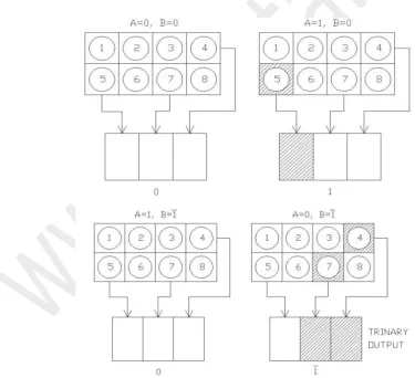
if the coded bits of A and that of B are superimposed, the possible combinations are shown in fig. 4(a). If we take only the respective contribution of light from the sub-cell number 4, 5 and 7 in the superimposed structure then we can get the resultant bits of addition represented spatially by the output digits 0, 1 and in the form of spatially coded pattern as shown in fig.
4(a). Here it is clear that in the spatially coded output bit of the result of addition we can see three sub-cells receive light, which indicates the representation of bit 0. Similarly, when light exists only in the first (left most) sub-cell, it indicates 1 and when the light exists in the two right most sub-cells, it indicates .
Volume 02, No. 4, April 2016
P
age
94
Thus we can exploit all the four possibilities of MTN based parallel and carry-less operation (addition). Here it is obvious that this coding can be achieved by other encoding/decoding technique. It is known that the Most Significant Bit (MSB) of the both MTN and the result is 1. Therefore if we take the light contributions from 4, 5 and 7 sub-cells of the coded pattern of MSB 1 of the MTN, we can produce the MSB 1 in the trinary result. This case of MSB representation is shown in fig. 4(b).
Fig.4(b). The output form of representation of MSB of B coded data (which is also the MSB of the result).
5. CONCLUSION
The methodology described above is an all-optical technique, which runs in parallel as well as carries-less. Here to implement this scheme we require no spatial light modulator, no optical/optoelectronic/electronic switching system. Only by coding of the inputs spatially and by simple superimposition of the inputs we can implement the scheme, where the output bits of addition are received also by the spatial coding. It is very much important to mention two points in connection to the implementation. First of which is that for superimposition of the images of the two spatially coded input bits, we can exploit a lens based system or fibre optic wave guide. The second point is that the result of the data addition is obtained in trinary not in MTN. The parallel conversion of trinary number to its equivalent binary form can be
done.4 However, if the conversions of binary number to its equivalent MTN and the
conversion from a trinary number (result) to its equivalent binary form are done in parallel then the whole process of binary addition (where the inputs are in binary and the result of the addition is also in binary) will come to be a system of parallel processing. The above scheme described in this communication is an important part of the whole scheme, where only the addition operation between a bit coming from a MTN and another bit coming from a binary number is performed. This part is fully parallel in nature with the proper exploitation of the inherent parallelism of optical signal.
The fundamental limitation of this scheme is diffraction. To avoid this limitation we may use optical fibre as wave guide with the proper control of the input and output cell sizes. We should take care about the format of the both input structures. The dimension of the structures should necessarily be same in size; otherwise problem in superimposition will arise.
As the above scheme is suitable and proper exploitation of optical signal, we can design different optical logic gates as well as arithmetic operations to construct super-computing
Volume 02, No. 4, April 2016
P
age
95
REFERENCES
i. R.P.Bocker, B.L.Drake, M.E.Lasher and T.B.Henderso, “Modified signed-digit addition
and subtraction using optical symbolic substitution”, Appl. Opt., vol.25, pp.2456-2457, 1986.
ii. B.L.Drake, R.P.Bocker, M.E.Lasher, R.H.Patterson and W.J.Miceli, “Photonic
computing using the modified signed-digit number representation”, Opt. Eng. vol.25 (1), pp.38-43, Jan. 1986.
iii. A.K.Ghosh and A.Basuray, “Binary to modified trinary number system conversion and
vice-versa for optical supercomputing”, Natural Computing, vol. 9 (4), pp.917-934, Dec. 2010.
iv. A.K.Datta, A.Basuray and S.Mukhopadhyay, “Arithmetic operations in optical
computations using a modified ternary number system”, Opt. Lett., 14 (9), pp.426-428, May, 1989.
v. T.Chattopadhyay, “Designing of all-optical tri-state logic system with the help of optical
non-linear materials”, Jr. of Nonlinear Optical Physics & Materials, vol.17 (3), pp.315, Jan. 2008.
vi. K.Huang and A.Louri, “Optical multiplication and division using modified signed digit
symbolic substitution”, Opt.Eng., vol.28, pp.364, 1989.
vii. A.A.S.Awwal, M.N.Islam and M.A.Karim, “Modified signed-digit trinary arithmetic by
using optical symbolic substitution”, Appl. Optics, vol.31 (11), pp.1687-1694, 1992.
viii. S.Lin, Y.B.Ki, and F.Lombardi, “CNTFET-based design of ternary logic gates and arithmetic circuits”, Nanotechnology, IEEE Transactions, vol.10 (2), pp.217-225, Nov. 2009.
ix. A.K.Maiti, J.N.Roy and S.Mukhopadhyay, “All-optical conversion scheme from binary