A SOFTWARE TESTING APPROACH BASED ON
BEHAVIORAL UML MODELS
Dominykas Barisas, Eduardas Bareiša
Software Engineering Department, Kaunas University of Technology Studentų St. 50, LT−51368 Kaunas, Lithuania
e-mail: [email protected]
Abstract. The aim of this paper is to describe a systematic way to construct tests from a formal software specifica-tion for validating a system implementaspecifica-tion. In order to achieve this goal, the specificaspecifica-tion could be extended to create UML states that directly address those aspects of the system we wish to test. The presented technique generates test cases from UML communication and state machine diagrams which allow testing a correct class integration of object-oriented software. UML state machine diagrams provide a good way for test generation in a form that can be easily manipulated. The concept of the technique and an example model are presented.
1. Introduction
Model-based testing has become popular not only in software design and development, but is widely used for testing. There is a number of advantages as well as difficulties and shortcomings of various model-based approaches. Many object-oriented tech-niques have been used as solutions to address the in-creasing demand for assuring software quality.
Many researches were done to ensure the correct software object functionality, however a large amount of errors are introduced by object integration. Many different UML models have been used for object integration testing including state machine, sequence and communication diagrams [1, 2, 3]. Object-orien-ted systems are based on their object interactions and incorrect behaviors are observed during integration such as missing functions, various conflicts between objects.
The technique we will present in this paper im-proves integration testing of object-oriented software by taking into account all class states interacting in a communication diagram. There are many researches made on testing system state-based behavior using state machine or UML interaction diagrams for the interacting behavior [4, 5, 6, 7]. In this paper, system object interactions in all possible states will be modeled using state machine and communication diagrams.
2. The Testing Technique Proposal
We propose a testing model which is created by generating communication and state machine diag-rams. The main focus is on testing all possible state interactions between objects in the model [8]. As men-tioned before, our approach can be used to test the
object integration, therefore it should be applied during the class integration phase.
2.1. The Testing Process Concept
The process can be separated into these activities: • Construction of UML communication diagram. • Defining state machine diagrams corresponding to
the objects from communication diagram.
• Test path generation based on all path coverage criteria [9] and test execution. Paths from the test model are executed and object states before and after execution of each message in a test path are stored [10]. States of the objects are defined using state invariants.
• Comparison of the object states after test execution and the expected states from the model. The test case is considered to have failed in case the object state is not in the expected state [11].
Figure 1 illustrates the described approach with
more details.
Test path generator Collaboration
diagram Statecharts
Generated test data
Stored results Test paths
in OCL
Execute tests Result comparison
Test results Invariants of
states
Figure 1. A chart representing a concept of the proposed testing process
-senderClass:Class -receiverClass:Class -number:int
-operation:int
ConnCollaboration
-acceptingState:State -sendingState:State
ConnState
1 0..n
Figure 2. Class diagram representing connections in the test model
2.2. Building UML Test Model
An example of the described model will be pro-vided in this section. The simulation of an Automated Teller Machine application will be modeled [13]. The system is started up when the operator turns the operator switch to the "on" position. A session is star-ted when a customer inserts an ATM card into the card reader slot of the machine. The ATM pulls the card into the machine and reads it. (If the reader cannot read the card due to an improper insertion or a damaged stripe, the card is ejected, an error screen is displayed, and the session is aborted). The customer is asked to enter his/her PIN, and is then allowed to perform one or more transactions, choosing from a menu of possible types of transaction in each case. When the customer is through performing trans-actions, the card is ejected from the machine and the session ends. A transaction is aborted due to a number of invalid PIN entries or after the “Cancel” button is pressed by user.
A transaction is started within a session when a customer chooses a transaction type from a menu of options. If PIN is valid, any steps needed to complete the transaction will be performed. If the bank reports that the customer's PIN is invalid, then an attempt will be made to continue the transaction. If the customer's card is retained due to too many invalid PINs, the transaction will be aborted, and the customer will not be offered the option of doing another one.
If a transaction is cancelled by the customer, or fails for any reason other than repeated entries of an invalid PIN, a screen will display the information for the customer about the reason of the transaction failure. The customer may cancel a transaction by pressing the Cancel key as described for each indivi-dual type of transaction below.
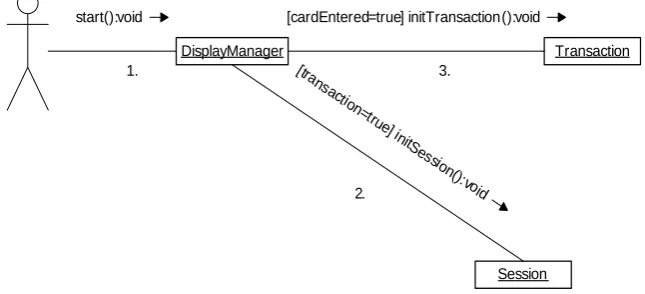
A corresponding communication diagram is shown in Figure 3.
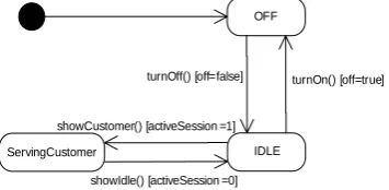
Objects from communication diagram have corres-ponding state machine diagrams representing different states of the objects as illustrated in Figure 4 to 6.
DisplayManager Transaction
Session [cardEntered=true] initTransaction():void
[tra nsactio
n=true] initSes
sio n():vo
id start():void
1. 3.
2.
OFF
IDLE ServingCustomer
turnOn() [off=true] turnOff() [off=false]
showIdle() [activeSession =0] showCustomer() [activeSession =1]
Figure 4. DisplayManager state machine diagram
Sending to Bank
Completing Transaction Handling Invalid PIN
send() [specificsCorrect =true]
checkPIN (pin:int ) [pin!=myPIN]
checkPIN (pin:int) [pin=myPIN]
checkPIN (pin:int) [pin=myPIN] Getting Specifics
Figure 5. Transaction state machine diagram
The communication diagrams model focuses on the use case execution by calling system level opera-tions. The object state machine diagram contains its states and the messages the object can receive in those
states. There is a set of messages with state informa-tion of each object in the communicainforma-tion diagrams.
The goal of the model is to create a graph combi-ning communication and state machine diagrams. There is a number of vertices created for the classes. They represent different states in which the message can be received. Vertices belonging to the same class are grouped in the box. In this way the graph is built combining communication and state machine diag-rams. The example graph of ATM application is shown in Figure 7. All objects in the graph have information about the class name and state. Con-nections between objects in communication diagram have unique numbers identifying them. State machine diagram connections contain information about the condition.
Performing Transaction Choosing Transaction Reading PIN
readPIN() [cardRead=true]
end() [calcel =true || invalidPIN >3] Ejecting Card
Reading Card
getTransaction(transactioId:int) [userValidated=true]
startTransaction(transactioId:int) [userValidated=true]
end() [calcel=true || invalidPIN >3] end() [calcel=true
|| invalidPIN >3]
end() [cardRead=false]
Figure 6. Session state machine diagram
Start
1.
3. 2.
Performing Transaction Choosing Transaction Reading PIN
[cardRead=true]
[calcel=true || invalidPIN >3] Ejecting Card
Reading Card
[userValidated=true]
[userValidated =true] [calcel=true || invalidPIN >3]
[calcel=true || invalidPIN >3]
[cardRead=false]
Sending to Bank
Completing Transaction Handling Invalid PIN
[specificsCorrect=true]
[pin!=myPIN]
[pin=myPIN]
[pin=myPIN] Getting Specifics
OFF IDLE
ServingCustomer [off=true]
[off=false]
[activeSession =0]
2.3. Covering Paths in the Graph
The generated test paths test communication bet-ween classes, each of them having states. This testing path starts from the first graph node and has a set of messages for the communication. When constructing a path, only those state machine diagram connections are selected which are valid for the corresponding connection in the communication diagram. However, it is not always possible to execute all paths due to the guard conditions.
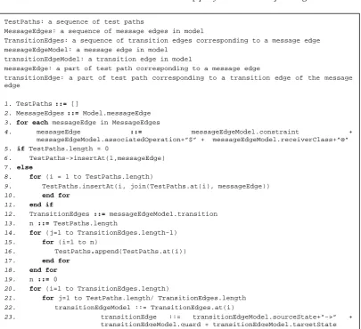
The main steps to generate test paths are presented in Figure 8. Every generated path is stored as a string containing a chain of connections between objects in appropriate states. These tests paths can be presented as an OCL set of strings. Every connection contains detailed information about the message, therefore messages in test paths are identified by numbers and names. Each message contains information regarding the test path, the condition which is needed for condi-tional messages only, message and class names, state,
guard, result state. They are combined in the following way:
Sequence_nr:[iteration][Condition]msg_name@class name@state_id->[Guard]result_state
The whole test path is composed of a set of such messages combined with each other. In order to test the integration of application completely using the proposed approach, each state connection of the diagram has to be executed at least once. Then generated test paths are parsed in order to identify objects and states. The result of one test path generation for ATM application would look like as follows:
1. start$DisplayManager@IDLE->[activeSession=0]ServingCustomer
2. transaction=true]initSession$Session@Reading Card->[cardRead=false]Ejecting Card
3. cardEntered=true]initTransaction()$ Transaction@Getting Specifics-> [specificsCorrect=true]Sending to Bank
Figure 8. A test path construction algorithm
Every path is read to identify the classes and their initial states. The sequence numbers in a test path de-termine the sequence of sending the messages. Execu-tion of each test path requires test data. These data
have to be provided by the user or generated automa-tically.
TestPaths: a sequence of test paths
MessageEdges: a sequence of message edges in model
TransitionEdges: a sequence of transition edges corresponding to a message edge
messageEdgeModel: a message edge in model
transitionEdgeModel: a transition edge in model
messageEdge: a part of test path corresponding to a message edge
transitionEdge: a part of test path corresponding to a transition edge of the message edge
1. TestPaths::= []
2. MessageEdges::= Model.messageEdge
3. for each messageEdge in MessageEdges
4. messageEdge ::= messageEdgeModel.constraint +
messageEdgeModel.associatedOperation+”$” + messageEdgeModel.receiverClass+”@”
5. if TestPaths.length = 0
6. TestPaths->insertAt(1,messageEdge)
7. else
8. for (i = 1 to TestPaths.length)
9. TestPaths.insertAt(i, join(TestPaths.at(i), messageEdge))
10. end for
11. end if
12. TransitionEdges ::= messageEdgeModel.transition
13. n ::= TestPaths.length
14. for (j=1 to TransitionEdges.length-1)
15. for (i=1 to n)
16. TestPaths.append(TestPaths.at(i))
17. end for
18. end for 19. n ::= 0
20. for (i=1 to TransitionEdges.length)
21. for j=1 to TestPaths.length/ TransitionEdges.length
22. transitionEdgeModel ::= TransitionEdges.at(i)
2.4. Test Execution and Test Result Assessment After the model has been created, the test paths are generated and executed using the provided test data, results are evaluated and saved in a file. Test
paths are composed from the sequences of messages starting from the first and ending at final nodes in the
graph. UML model has to be presented in XMI format, so that it can be parsed and needed objects
identified. Each message is retrieved from the communication diagram. Further all states of the sending objects are stored. Only those objects states are selected which are capable to receive the message.
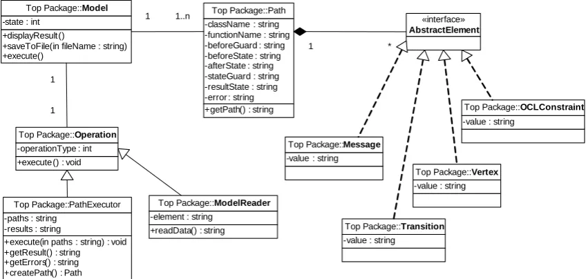
Figure 9 shows the static structure of test execution environment.
In order to be able to execute test paths, test data using a state invariant have to be generated manually.
These test data include initial message parameter values and class variables needed to set states for the objects in communication diagram. The user can add test values manually by picking random values from the state invariants and saving them in a data file. Test data are provided for the methods called in test paths, then the application is tested and results are stored in a result file. This file contains object states before and after each test path message. Afterwards, the test results are compared with the expected results. Object states before and after the message in the test path compose the expected result. The test path is success-fully passed if all object states are equal. Test results and message names are saved in a file.
+displayResult()
+saveToFile(in fileName : string) +execute()
-state : int
Top Package::Model
+getPath() : string -className : string -functionName : string -beforeGuard : string -beforeState : string -afterState : string -stateGuard : string -resultState : string -error : string
Top Package::Path
+execute(in paths : string) : void +getResult() : string +getErrors() : string +createPath() : Path -paths : string -results : string
Top Package::PathExecutor
-value : string Top Package::Message
-value : string
Top Package::Transition
-value : string Top Package::Vertex
-value : string
Top Package::OCLConstraint
1 1..n «interface»
AbstractElement
+readData() : string -element : string
Top Package::ModelReader
1 1
+execute() : void -operationType : int
Top Package::Operation
1 *
Figure 9. Class diagram of the testing framework implementation
All test path combinations have to be generated to fully cover all possible sequences in the graph. The number of combinations depends on the model size as it is illustrated in Figure 10.
Figure 10. Number of test paths dependence on the number of classes assuming that each object has three states
It is obvious that the number of different com-binations of test paths can grow exponentially when the software system is large. This disadvantage of the proposed technique needs to be improved in the future.
3. Conclusions and Future Work
This paper presented a formal technique for the testing process based on UML model consisting of communication and state machine diagrams. Using this approach, the object graph is generated and the system is tested by checking communication between objects in different states. The proposed technique is suitable for the systems where the functionality of one object depends on the state of another object. The accomplished tasks are the construction of UML model, implementation of test graph generation and assessment of results.
use it for integration testing widely. In real software systems, the number of state transitions can grow ex-ponentially, therefore the testing process may become difficult and time consuming.
One of the future investigations could be finding a solution to identify a set of paths which has the high-est possibility to detect faults in the system. Another improvement of this technique would be finding a way for the automated generation of test data.
References
[1] A. Abdurazik, J.Offutt. Using UML Collaboration
Diagrams for Static Checking and Test Generation. Third International Conference on the Unified Model-ling Language, York, UK. 2000, Vol.1939, 383 - 395.
[2] L.C. Briand, M. Di Penta, Y. Labiche. Assessing
and Improving State-Based Class Testing: A Series of Experiments. IEEE Transactions on Software Engi-neering. 2004, Vol.30, 770 - 783.
[3] L. Briand, Y. Labiche. A UML-Based Approach to
System Testing. Proceedings of the 4th International Conference on The Unified Modeling Language, Mo-deling Languages, Concepts, and Tools, 2001, Vol. 2185, 194 - 208.
[4] S.K. Kim, L. Wildman, R. Duke. A UML Approach
to the Generation of Test Sequences for Java-based Concurrent Systems. Proceedings of the Australian Software Engineering Conference, IEEE, 2005, 100 - 109.
[5] Y. Jiong, W. Ji, C.Huowang. Deriving Software
Statistical Testing Model from UML Model. Third International Conference on Quality Software, Dallas, Texas, USA, IEEE, 2003, 343.
[6] S. Rayadurgam, M.P.E. Heimdahl. Test-Sequence
Generation from Formal Requirement Models. 6th IEEE International Symposium on High Assurance Systems Engineering. 2001, 23 - 31.
[7] P. Chevalley, P.Thevenod-Fosse. Automated
Gene-ration of Statistical Test Cases from UML State Diag-rams. Proceedings of the 25th Annual International Computer Software and Applications Conference, IEEE, 2001, 205 - 214.
[8] M. Badri, L. Badri, M.Naha. A Use Case Driven
Testing Process: Towards a Formal Approach Based on UML Collaboration Diagrams.Formal Approaches to Software Testing, LNCS. ISBN/ISSN: 3-540-20894-1. 2004, Vol. 2931, 223 - 235.
[9] J. Offutt, A. Abdurazik. Generating Tests from UML Specifications. UML’99 – The Unified Modeling Lan-guage. Beyond the Standard. Proceeding of the Se-cond International Conference, Fort Collins, CO, USA, 1999, Vol.1723, 416 - 429.
[10] P. Fröhlich, J.Link. Automated Test Case
Genera-tion from Dynamic Models. ECOOP 2000 –
Object-Oriented Programming, LNCS, ISBN:
978-3-540-67660-7. 2000, Vol.1850, 472 - 491.
[11] S. Ali, L.C. Briand, M.J. Rehman, H. Asghar, M.Z.
Iqbal, A.Nadeem. A State-based Approach to Integ-ration Testing based on UML Models. Information and Software Technology, 2007, Vol.49, 1087 - 1106.
[12] M. Benattou, J.M. Bruel, N.Hameurlain.
Genera-ting Test Data from OCL Specification. Internal Re-search Report R2I-02-01, Universite de Pau et des Pays de l'Adour, France, 2002.
[13] R.C.Bjork. ATM Simulation. Gordon College,
Wen-ham, MA, 2004.
[14] Š. Packevičius, A. Ušaniov, E. Bareiša. The use of model constraints as imprecise software test oracles. Information technology and control, Kaunas Univer-sity of Technology, Kaunas: Technologija. ISSN 1392-124X. 2007, Vol.36, No.2, 246 - 252.