1. Introduction and Problem Statement. The main aim in multiagent systems is to provide principles for the building of complex distributed systems that involve multiple agents and to take advantage of the mech-anisms for cooperation and coordination in these agents’ behaviours. However, building multiagent applications for complex and distributed systems is not an easy task [9]. Add to that the development of industrial-strength applications, which requires the availability of appropriate software engineering methodologies. Although there are several good MAS development methodologies such as those reviewed in section 2, we contend that none of them stands out as both a comprehensive and a business-accessible methodology. MAS exhibit all the tradi-tional problems of distributed and concurrent systems, and in addition bring difficulties arising from flexibility in requirements and sophisticated interactions [23], all of which result in making it very challenging to define a MAS development methodology. It was stated in 2008 in the Agentlink Roadmap that “One of the most funda-mental obstacles to the take-up of agent technology is the lack of mature software development methodologies for agent-based systems.” [17], and we believe this remains largely true still today.
It is unfortunately apparent that none of the existing MAS development methodologies has seen main stream take-up. We put forward some reasons of our own for this lack of impact, as well as observations from some analyses in the literature, to identify those we regard as the most crucial:
1. Lack of support for inexperienced developers; typically, a methodology will require a good knowledge of agent concepts, because developers need to specify all the semantic components of their agents. This presents a significant barrier for commercial applications and may explain why adoption of the MAS paradigm is rarely encountered.
2. The absence of an holistic view of the system logic and its cognitive aspects; this has the potential to lead to confusion and ambiguity in both analysis and design phases.
3. Incomplete coverage (within a single methodology) of the development life-cycle phases; some offer design and analysis tools but no support for deployment, while others offer theory but supporting tools may not (yet) exist.
4. The gap between design models and existing implementation languages [19]; this leads to great difficulty for programmers, as they try to map the complex designs into executable code.
5. Support for implementation; many current methodologies do not include an implementation phase and of the ones that do, such as Tropos [3], its implementation language does not explain how to implement beliefs, goals and plans, nor how to reason about agent communication.
6. Lack of complete formal representation of MAS concepts; we note the of work by Wooldridge [25], and Luck [16], but observe that neither of these can be considered complete. Even though a partial approach may be effective, the question remains, which concepts to formalize? And what is the best way to specify and describe them?
Our proposed methodology, Modelling Self-managing Multi Agent Systems (MSMAS) is intended to solve most, if not all, of the above issues. It also aims at being more accessible to a wider range of academics and
∗Department of Computer Science, University of Bath, UK ([email protected]). †Department of Computer Science, University of Bath, UK ([email protected]).
software engineers through the support of a formal representation and semi-formal visual modelling, specified through the metamodel.
The purpose in defining a metamodel is to describe the concepts of MSMAS and to highlight their relation-ships, as a first step in making any system modelled using MSMAS easily transferable to any MAS technology. The metamodel represents organizational concepts explicitly and uses dynamic planning in order to support self-management. In the following sections we highlight related work in section 2 then we present an overview of the proposed methodology and give some details of its three phases with the inclusion of a sample diagram of each model in section 3, followed by the details of the metamodel in section 4 and finally we conclude the paper and discuss future work in section 5.
2. Related Work. In this section we begin with a short review of some of the most prominent MAS methodologies: GAIA [24], MaSE – Multiagent Systems Engineering [6], Prometheus [18], and Tropos [3], amongst others. Then we outline and evaluate two particular metamodels that we consider offer the most complete efforts at defining a unified metamodel for MAS, namely the work of Hahn et al [13] and Beydoun et al [2].
2.1. Selected MAS Development Methodologies.
GAIA Methodology: GAIA [24] is a general methodology that supports both micro (agent structure) and macro (organisational structure) development of agent systems. It was proposed by Wooldridge et al in 2000 and subsequently extended by Zambonelli et al. [26] to support open multi-agent systems. It has two phases that covering analysis and design. GAIA is both lengthy and complex in these respects, as well as lacking an implementation phase.
MaSE Methodology: Multiagent Systems Engineering (MaSE) [6] covers the full development life cycle from an initial system specification to system implementation. It has two phases, comprising seven steps in all and offers tool support in all phases. MaSE does not enforce the use of any particular implementation platform, but it has a steep learning curve for inexperienced users.
Prometheus Methodology: Prometheus [18] aims to be suitable for non-expert users to design and develop MAS. The methodology has three phases: 1. System Specification, 2. Architectural Design, and 3. De-tailed Design. Prometheus has a tool that supports the design process, including both consistency checking and documentation generation. Although Prometheus is more practical than many other approaches it does not fully connect the system model to an execution platform.
TROPOS: Tropos [3] distinguishes itself from other methodologies by paying great attention to the require-ments analysis, where all stake-holders requirerequire-ments and intentions are identified then analysed. The modelling process consists of five phases and uses JACK for the implementation, the developers would need to map the concepts in their design into JACK’s five constructs. Tropos offer some guidelines to help in this process, but it seems very lengthy and complex.
2.2. PIM4Agents: A Platform Independent Metamodel for Multiagent Systems. The principles of the Model Driven Development (MDD) Framework of the Object Management Group (OMG)1 define how a
visual, model-based approach could be used to integrate a number of technologies used in software development. Aiming to follow this approach, Hahn et al [13] examine various multiagent metamodels including Aalaadin, ADELFE, Gaia and PASSI, then propose a unified MAS metamodel by merging the metamodels of ADELFE, Gaia and PASSI to cover all of their aspects. The problem with this approach is that it does increase the complexity of modelling MAS systems and although a unified metamodel can help in moving MAS towards a standard form, it makes it difficult to satisfy some circumstances where a specifically focused structural view of a MAS is needed.
Hahn et als’ unified metamodel for MAS adopts multiple points of view to cover all the features in the different technologies. These views we now summarise:
1. Multiagent View: focusses on the main components of any MAS; this covers agents, their capabilities and the primary concepts of any MAS such as cooperation, interaction and environment.
2. Agent View: describes each individual agent and the capabilities it uses to achieve its tasks, as well as the roles it plays in the context of the MAS.
3. Behavioural View: focusses on plan composition, specification of how atomic tasks are done and how data flows within system control constructs.
1
(iii) Reconciliation of definition differences to build a consistent set of metamodel terms, and (iv) Designation of the chosen concepts into two sets: design-time and runtime, where the central design-time concept is the system as an agent-oriented system while the central runtime concept is the environment wherein agents reside. In FAML, an agent has internal and external concepts, and the classes that relate to the agent’s internals at design-time are calledagent definition level, while those that relate to the agents internal aspects at runtime are calledagent level. Classes that relate to the agents external aspects at design-time are calledsystem level, while classes that relate to agent external aspects at runtime are calledenvironment level. In summary:
1. Design-time aspects: Views the system as an agent-oriented structure that satisfies both functional and non-functional requirements. Roles are also used to describe the system. They are normally related to tasks either as responsible for a task or as a collaborator in a task.TheInitialStateconcept is used to initialize the concept of AgentDefinition that is used only at runtime. An AgentDefinition consists of an initial state and a number of plan specifications, and each is composed of a number of action specifications. A system also has facet definitions: these are the aspects of the environment with which the agents can interact.
2. Runtime aspects: The environment is an essential part of the system: it is where the agents reside and it provides the facets they need to interact. In FAML, the environment has a history which is a composition of all message events and facet events that occurred in the environment. Agent internals at runtime comprise the collection of beliefs, desires, and intentions an agent can hold including support for basic BDI concepts, but those are not compulsory. Finally the actions that make an agent plan can be facet actions or message actions.
Both FAML and PIM4Agents offer a generic approach to the description of any MAS, and have a compre-hensive metamodel that fits all views and approaches of developing MAS. As such, they are a great contribution that have together helped us to verify that our concepts could be mapped to other metamodels. However, we find that the inclusion of so many concepts in FAML has led to an increase in complexity and introduced a steep learning curve to be faced by new user. To address this issue and make the modelling process more straightforward, we have intentionally designed MSMAS to offer a carefully selected subset of MAS concepts that are essential to the description of any MAS, but especially those concepts that are more aligned to, and commonly used within, a business context.
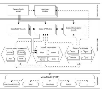
3. MSMAS Methodology Overview. MSMAS consists of three phases that cover the full life cycle of multiagent systems development. The elements of each phase and the connections between them are show in Figure 3.1. We now outline each of the phases:
1. The first phase focusses on System Requirements gathering: this allows the system designer to describe many possible use case scenarios as well as to specify a high-level system goals. It has two diagram types; theSystem Goals Diagram andUse Cases Diagrams.
tar-System Goals Model Declarative Norms Plans Beliefs Goals ENV Agent Actor Service System Participants Models Basic BP Models
Specific BP Models
Use Cases Models Diagram Data Type Descriptor Uses Drives Matches System Participants System Repositories Communication Components Message
Meta Model (RDF)
AgentSpeeak(JASON) JADE AgentScape JANUS ...
S y s te m R e q u ir m e n ts D e ta il e d S ys te m D e s ig n Im p le m e n ta ti o n Comm. data type Protocol Plan Belief
Fig. 3.1: MSMAS Overview
get execution languages/platforms. The system designer can start this phase either from the business process (BP) view or the system participant view. The BP view requires the completion of Specific Business Process ModelsandBasic Business Process Modelsdiagrams. Experienced users with a good knowledge of the multiagent paradigm can alternatively start from the System Participants Modelsand the definition of their entities (Agent–Actor–Service–Environment) as well as the definition of communication components (Protocol–Message) alongside the usage or definition of (Goals–Plans–Norms–Beliefs).
3. Finally, the third phase is the implementation and execution phase where the user can verify the system design and export the Metamodel file as RDF or choose to generate code in one of the supported execution languages/middlewares such as Jason, AgentScape etc.
In the following sections we describe each of these phases and their modelling diagrams/components in more detail and give some examples. The examples are based on elements of the inventory system described in [10]. This system comprises service provider agents (SPA), administrator agents (AA) and a central database agent (CDBA) whose task jointly is to meet the following requirements: (i) The SPA must be able to publish/update its stock-level information in the central database (ii) The SPA must provide stock-level information about any number of its catalogue items on request from another agent (iii) The SPA must report any errors in transaction with other agents (iv) The SPA must report any suspected data transmission failure (v) The AA must log and may take corrective action in response to an error reported by a SPA. The processes discussed later mostly concern the handling of the Supplier Stock Level File (SSLF), from getting a new version from a supplier to its publication in the central database.
Fig. 3.2: System Goals Diagram
phase: System Goals Modeland Use Cases Models.
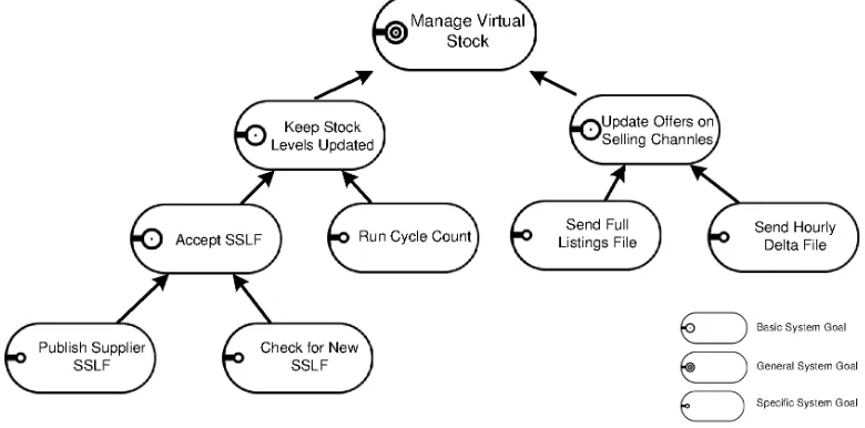
3.1.1. System Goals Model. Every system should have a set of goals; these are simply the motivations for building the system: the system designer does not need at this stage to specify the goals in great detail, rather the goal hierarchy should be constructed until it reaches the level of detail whereby every goal can be fulfilled byonlyone basic business process. Systems goals are the drivers for all the diagrams of the next phase. The system goal is basically the system status it is wished to achieve. The system goals definition should not to be confused with the common agent goals: in our model the system goals are procedural, in other words the goal name is similar to a method in a traditional programming language. This is very useful to divide—if we take a top to bottom approach—the system from one unit to a group of functions. At the same time, it helps to show how a particular group of actions may lead to the fulfilment of a single big system function. Figure 3.2 shows an example System Goals Model.
The system goals model contains three types of goals (i)General System Goal: Any system should have
only one General System Goal. This should express the major reason for building the system. (ii) Specific System Goals: These are more functional goals that can be achieved by one or more business processes; each Specific System Goal can have a number of sub-goals. (iii)Basic System Goals: These are leaves of the goals tree; they cannot have sub-goals.
3.1.2. Use Cases Models. Use cases function as a clarification of some or all the system functionalities, in this step the system designer can create some models of the most important functions for future reference. The use cases are used in our methodology to help the system designer to think through the different functions of the system and possible issues to be considered. The use case diagram normally shows how different system participants interact, or which steps they take to carry out a system function.
Figure 3.3 shows an example use case diagram, where there are two system participants: a software agent (Supplier) and software service (Translator), and four functions. The arrows show the sequence of execution and the connectors between the agent and the function define responsibilities.
3.2. Detailed System Design Phase. The aim of the Detailed System Design phase is to define all the system components, their detailed structure and the ways they can interact with each other. There are three different diagram types in this phase;Specific Business Process Models,Basic Business Process Models, and System Participants Models. To complete these diagrams, the system designer needs to define/use different types of supporting entities, which are held in the form of repositories or standard descriptors.
Get Connection
Download SSLF Translate SSLF Submit Standard
SSLF Supplier Agent
Translation Service
Fig. 3.3: Use Case Diagram (Publish Supplier Stock Levels File (SSLF)
3.2.1. Business Process Models (BPM). Generally, business process modelling is a way of representing organizational processes so that these processes can be understood, analysed, improved and enacted. The drawback to most BPM techniques is their procedural nature, which can lead to over-specification of the process, and the need to introduce decision points into execution that are hard to know in advance and unsuited to MAS modelling. We use declarative style modelling to describe our BPs using the Declarative Service Flow Language (DecSerFlow) [20]. More details of this are given in section 3.2.2.
Business Process Models (BPMs) are derived directly from the system goals and they are used to describe and identify the steps needed to achieve one or more of the system goals, these steps form the system plans. For eachSpecific System Goal there is at least one BPM. Each Sub-Specific Goal is represented as anActivity inside its Super Goal BPM. Business Process Models are eitherSpecific Business Process—that is, derived from a Specific System Goal—orBasic Business Process, that describes a Basic System Goal.
3.2.2. Modelling BPs and Specifying System Norms Using DecSerFlow. According to Jennings [14] Commitments and Conventions Hypothesis: all coordination mechanisms can ultimately be reduced to (join) commitments and their associated (social) conventions. Introducing conventions to the system participants’ interactions can be achieved through one of three approaches (i) reducing the set of possible options by restricting and hard coding all these conventions in all agents, (ii) enforcing these conventions at the protocol level that all system participants follow, so there is no way for the agent to violate the conventions even if it tries to – known as regimentation, as in [11] – or (iii) using the norms only to influence the system participants’ behaviour as suggested by Dignum et al [7] – known as regulation.
We adopt a declarative style for modelling our BPs, namely DecSerFlow as proposed by van der Aalst and Pesic [20], which offers an effective way to describe loosely-coupled processes. Consequently, instead of describing the process as a directed graph, where the process is a sequence of activities and the focus of the design is on “how”, the designer is able to concentrate on “what”, by adding constraints in the activities model, as well as rules to be observed at execution time. For constraint specification, DecSerFlow uses LTL (Linear Temporal Logic) as the underlying formal language and these constraints are given as templates, that is as relationships between two (or more) activities. Each constraint template is expressed as a LTL formula. We use DecSerFlow notation and its underlying LTL formal representation.
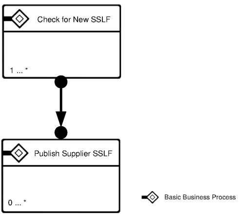
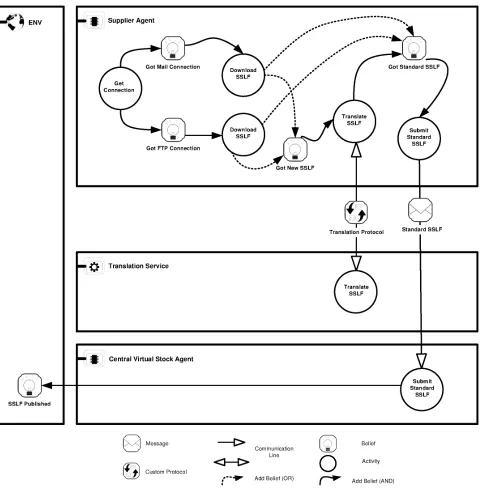
Fig. 3.4: Specific Business Process Diagram (Accept SSLF)
Figure 3.4 shows an example diagram of the “Accept SSLF” – where SSLF is the Supplier Stock Levels File – Specific Business Process, which has two activities: (A) “Check for New SSLF” that is a sub-process to achieve the “Check for New SSLF” Specific System Goal and (B) “Publish Supplier SSLF” Basic Business Process to achieve “Publish Supplier SSLF” Basic System Goal. Both activities can run an arbitrary number of times, however theSuccession relationshiprequires that every execution of activity A should be followed by the execution of activity B and each activity B should be preceded by activity A. That relationship is formally expressed in LTL as: (A⇒ ♦(B))∧ ♦(B)⇒((¬B)⊔A)
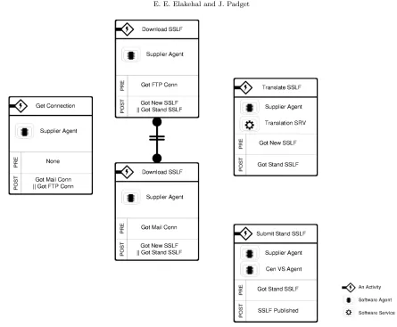
3.2.4. Basic Business Process. A Basic Business Processes is the most detailed BP model; it can contain any number of plans for the purpose of achieving just one Basic System Goal. The Basic Business Process diagram comprises a set of activities. Figure 3.5 shows a diagram for the “Publish SSLF” Basic Business Process, which has five possible activities; each activity is carried out by one or more system participants. Each activity has its own pre-conditions and post-conditions. There is no need to specify the execution sequence, because the activity whose conditions are met should start automatically. “Get connection” has no pre-conditions, which means it should start as soon as this “Publish SSLF” Business Process starts. There are two activities named “Download SSLF”, each of which has the same post-conditions but a different pre-condition. During execution, based on the available resources, the supplier agent can download the new SSLF from either a FTP or an Email account. To avoid duplication of execution of this activity, there is the not co-exists relationship that means only one of the two tasks “A” or “B” can be executed, but not both. The not co-exists relation is expressed in LTL as: ♦(A)⇐⇒ ¬(♦(B))
3.2.5. System Participants Models. System Participants Models are equivalent in context to Detailed Business Process Models. They offer a different view of the process by describing the detailed activities from the participants’ perspective. They define also how activity owners communicate with other participants. System Participants Diagram includes one box for each system participant (Agent–Actor–Service) and one for the Environment. This last allows for the definition of any external event caused by other system participants.
Fig. 3.5: Basic Business Process Diagram (Publish SSLF Business Process)
system participant (Actor), as proposed by [22] to allow for modelling a participatory team of software agents and human actors. This view is found to be more practical to support real-life scenarios where some decisions are necessarily assigned to humans to make. Finally, the system participant can be aSoftware Service, which is a piece of software that has a set of related functionalities together with policies to control its usage and is able to respond to any relevant requests from other software entities in a reactive manner.
System participants communicate using aCommunication Protocol, which is a set of rules determining the format and transmission of a sequence of data in the form of messages between two or more system partic-ipants. MSMAS offers a number of pre-defined native protocols, as well as allowing the user to define custom protocols.
During the detailed system design phase the user can define each entity from scratch or connect it with a definition file. All entity definitions are stored in the system repositories that hold System and Agent Plans, Environment and Agents beliefs, System and Agents goals, as well as allsystem processes, communications protocols,and system declarative norms.
3.3. Implementation Phase. The third and final phase of MSMAS addresses verification and consistency checking across all system models. The verified system model can be exported into oneMetamodel (RDF) . That metamodel is used to generate code for one of the supported execution languages, platforms or middlewares. 4. MSMAS Metamodel. MSMAS aims to allow the system designers to provide the absolute minimum description of a MAS that satisfies the answers to the following questions:
1. What is the purpose of building the system and its individual components? This question is answered by the definition ofSystems Goalsas the first core concept.
Fig. 3.6: System Participants Diagram (Publish SSLF)
systemBusiness Processesand their activities.
3. Who or what is responsible for the execution of each business process activity or each complete business process of the system? The question is answered through the definition of the third core concept of System Participants.
Multi Agent System
Institution Governor (ig) Institution Planner (
ip)
System Goals (SG)
System Participants ( SP)
Business Processes (BP)
Norms (N) Agent Actor ENV Service 1 * Specific Business Process
(BPsp)
Basic Business Process (BP ba)
1 *
1 *
Business Activity (BA)
1 * 1 1 * 1 * 1 *
System Participant Norms Normative Models 1 * 1 * 1 * 1 * 1 * 1 * 1 * 1 * Plans 1 * 1 * Goals 1 *
System Participants Goals 1 * System Plans
System Participants Plans
1 * 1 * 1 * Protocol 1 1 Belief Base 1 1 Native Custom Message Belief 1 1 1 1 1 Role capability 1 1 1 1 1 1 1 *
System General Goal
System Specific Goal System Basic Goal
1 * 1 1 Proactive Reactive 1 * Actions 1 1 1 1
Fig. 4.1: MSMAS Metamodel
by the desire for an explicit organizational model, normative system or institution, where agents are designed to be regulated by a set or norms, which are used by the individual agents to decide how to behave or are enforced through monitoring and punishment mechanisms. In our approach we have chosen to implement the organization mechanism explicitly to allow for easier management and transformation of our metamodel into any target programming language, whether that language provides programming constructs to implement the social concepts or not. Another advantage of our approach is that it allows any agent to play any role, as long as it does maintain the capabilities needed for such role and its individual goals are achieved through playing such role [21].
In MSMAS we have chosen to support the concept of institution explicitly, so the system designer should specify the different components of an institution during the design process. This concept is described in detail in section 4.4.
Finally a true MAS needs to be an adaptive system, that is a system that can dynamically respond to the changes in its observed environment states and can evolve and find new plans that utilise its resources, as well as lead effectively to the satisfaction of its goals. TheDynamic Planning feature is the final main concept and discussed in more detail in section 4.5.
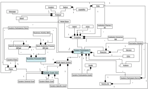
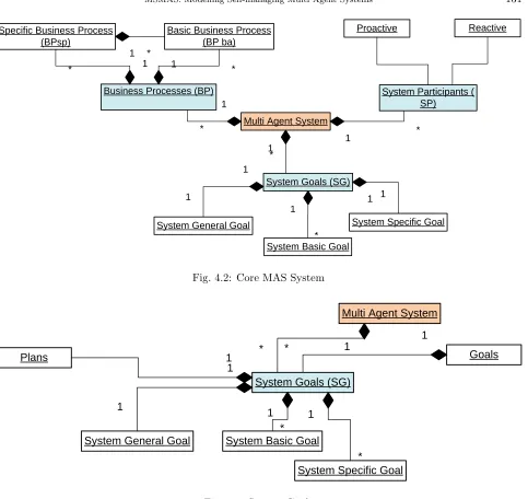
Figure 4.1 shows the full MSMAS Metamodel, where these three core concepts are highlighted, and Fig-ure 4.2 is a focused view of the core concepts with their immediate sub-concepts. In the following subsections we define these core conceptual areas and their related concepts.
System Basic Goal
Fig. 4.2: Core MAS System
Multi Agent System
System Goals (SG) 1 *
Plans Goals
1 * 1
System General Goal
System Specific Goal System Basic Goal
1
* 1
1
1 *
Fig. 4.3: System Goals
4.2. Business Processes. Business Processes are derived directly from the system goals and they describe and identify the steps needed to achieve one or more of the system goals, these steps forming the system plans. For eachSpecific System Goalthere is at least one Specific Business Process. And for each Basic System Goal there is one Basic Business Process, that is a collection of a number ofActivities. Each different sequence of activities that lead to completion of one business process is forming a system plan. Each system plan could be executed by one or more system participant. A collection of these activities into a system plan, to be executed by a system participant, form one system participant plan. Figure 4.4 shows all different types of Business Processes and their relations both the System Plans as well as the System Participants and Table 4.2 summarizes the definitions of all concepts supporting Business Process concept.
Multi Agent System Business Processes (BP)
1
* Specific Business Process
(BPsp)
Basic Business Process (BP ba)
-is1 1 *
*
Business Activity (BA)
1 * 1 * 1 * Plans 1 * System Plans
System Participants Plans
1 * 1
*
Fig. 4.4: Business Processes
Multi Agent System
System Participants ( SP) Agent Actor ENV Service 1 * 1 * 1 * 1 * Goals
System Participants Goals
1 *
System Participants Plans
1 * Protocol 1 1 Belief Base 1 1 Native Custom Message Belief 1 1 1 1 Role capability 1 1 1 1 1 * Proactive Reactive 1 * Actions 1 1
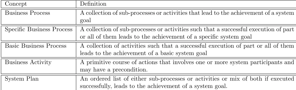
Business Process A collection of sub-processes or activities that lead to the achievement of a system goal
Specific Business Process A collection of sub-processes or activities such that a successful execution of part or all of them leads to the achievement of a specific system goal
Basic Business Process A collection of activities such that a successful execution of part or all of them leads to the achievement of a basic system goal
Business Activity A primitive course of actions that involves one or more system participants and may have a precondition.
System Plan An ordered list of either sub-processes or activities or mix of both if executed successfully, leads to the achievement of a system goal.
Table 4.2: Business Processes Concepts
of a series of actions to achieve one of more of their system participants goals. System participants actions do affect the state of the system, the internal state of the system participant itself or both, and they are important for the purpose of monitoring the overall state of the system and to discover any violation of the system norms that are associated with the role this system participant is performing.
Proactive system participants have a belief base, which is a set of facts about themselves, their environment, and other system participants. Each proactive system participant has a set of capabilities and typically it cannot perform a specific role without having the capabilities required for this role. Proactive system participants perform multiple roles during the course of system execution, however their actions need not violate the system norms associated with such roles. System participants communicate using one or more Communication Protocols, which are sets of rules determining the format and transmission of a sequence of data in the form of messages between two or more system participants. MSMAS offers a number of pre-defined (Native Protocols), as well as allowing the user to define (Custom Protocols). The communication protocol can have any number of messages of either of two types: (Inform Message andRequest Message), being the basic performatives defined by FIPA [12].
Multi Agent System
Institution Governor (ig)
System Participants ( SP)
Norms (N)
1 *
1
*
System Participant Norms Normative Models
1
* 1
*
1 * 1
* Protocol
1 1
Native Custom
1
1 Role
capability 1
1
1 1
1 1
Proactive
Reactive
Actions 1
1
-Manages
1
1
Fig. 4.6: Institution Concepts
Multi Agent System
Institution Planner ( ip)
System Goals (SG)
System Participants ( SP)
1
*
1 *
1 *
Plans 1
Proactive
Actions 1
1
Fig. 4.7: Dynamic Planning
The consequence of absence of permission is that a violation occurs – the action was not norm compliant – and if the violation is observed by an agent with the power to carry out some enforcement action, then there may be consequences for the offending agent. A more detailed discussion can be found in [8].
Role A specification of a behaviour pattern that the system participants should follow to carry out the function of such role
Capability The ability of a proactive system participant to perform set of functions specified within a certain role
Protocol A set of rules determining the format and transmission of a sequence of data in the form of messages between two or more system participants
Custom Protocol User defined communication protocol Native Protocol Predefined communication protocol
Belief A fact in the form of element in the state of a system participant, environ-ment, or both
Table 4.3: System Participants Concepts
different institutions, comprising different sets of norms, serving different purposes and that it is quite likely that an agent will be subject to the governance of more than one institution at the same time. Thus, the primary purpose of the institutional component of the metamodel is to provide a mechanism whereby different sets of constraints may apply to agent behaviour at different times, so that the behaviour of active entities that make the system work can be indirectly influenced without re-coding and re-starting.
4.5. Self-managing through Dynamic Planning. Planning in its simplest form is the process of finding a sequence of actions that leads to the achievement of a goal. We use “dynamic planning” for the on-demand process of finding all possible sequences of actions that lead to the achievement of a defined goal (state) based on the current state of the system and resource availability. The purpose of dynamic planning is to enable the system to overcome the failure of one or more of its components, thus realizing an aspect of self-management. Such behaviour is essential for designing business systems that are able to progress flexibly with their functions without the need to follow precisely a predefined course of actions. We are working on the definition of details of the dynamic planning aspect and our current and future research activities include the answering of questions such as: what is the best planning language to use? What is it realistic to expect dynamic planning to cover? Are the system agents self-contained, with full internal reasoning capability or should the planning service be offered for both global planning and system participants’ planning?
5. Discussion and Future Work. We have described briefly the key features of the MSMAS method-ology, which aims to (i) overcome the issues we have found with other MAS development methodologies and (ii) attract a wider range of users to adapt MAS concepts in business applications. MSMAS has clear and well-defined steps that should enable developers to design any small scale MAS and makes MAS concepts ac-cessible and easy to comprehend by business users as well as academics. The methodology is supported by a metamodel, presented here, that covers most common MAS concepts and supports formal system description for verification and implementation purposes. Our aim has not been to define a new MAS metamodel that fits with all methodologies or unifies all other metamodels, but rather to support our methodology with a small, well-defined set of concepts that could be easily understood and specified in a business context without com-promise on the most common agreed-on MAS concepts and structure. Our metamodel can be mapped to other metamodels, and could be used as a base for generating code.
The most important features supported by MSMAS are (i) formal specification using DecSerFlow notation, (ii) support for organizational view through the explicit definition of e-institutions, and (iii) the technical support of self-management through dynamic planning and usage of norms.
Two particular features of our methodology and its metamodel that stand out, are (i) the inclusion of an institution structure to support the organizational view of a MAS, and (ii) the use of dynamic planning to allow for self-management and thereby the opportunity for a higher degree of flexibility.
We are currently developing tools to support all the phases of MSMAS and a critical next step is a full evaluation of MSMAS in practice. Other planned future work include the establishment of the most appropriate means for specifying the system norms, describing system and agent plans to support dynamic planning, and deployment methods for distributed MAS systems.
REFERENCES
[1] C. Atkinson and T. K¨uhne,Model-Driven development: A metamodeling foundation, IEEE Software, 20 (2003), pp. 36–41. [2] G. Beydoun, G. C. Low, B. Henderson-Sellers, H. Mouratidis, J. J. G´omez-Sanz, J. Pav´on, and C. Gonzalez-Perez,
Faml: A generic metamodel for mas development., IEEE Trans. Software Eng., 35 (2009), pp. 841–863.
[3] P. Bresciani, P. Giorgini, F. Giunchiglia, J. Mylopoulos, and A. Perini,TROPOS: An agent-oriented software
devel-opment methodology, Autonomous Agents and Multi-Agent Systems, 8 (2004), pp. 203–236.
[4] M. Dastani,Programming multi-agent systems., in CLIMA, M. Fisher, F. Sadri, and M. Thielscher, eds., vol. 5405 of Lecture Notes in Computer Science, Springer, 2008, pp. 13–16.
[5] M. De Vos, J. Padget, and K. Satoh,Legal modelling and reasoning using institutions, in Proceedings of JURISIN 2010, S. Tojo, ed., vol. 6797 of LNCS, Springer, 2011.
[6] S. A. DeLoach, M. F. Wood, and C. H. Sparkman,Multiagent systems engineering., Int. Journal of Software Engineering and Knowledge Engineering, 11 (2001), pp. 231–258.
[7] F. Dignum, D. Morley, E. Sonenberg, and L. Cavedon,Towards socially sophisticated bdi agents, Multi-Agent Systems, International Conference on, 0 (2000), p. 0111.
[8] V. Dignum and J. Padget,Multiagent organizations, in Multiagent Systems, G. Weiss, ed., MIT Press, 2nd
ed., 2012. In press.
[9] S. Edmunson, R. Botterbusch, and T. Bigelow,Application of system modeling to the development of complex systems, in Digital Avionics Systems Conference, 1992. Proceedings., IEEE/AIAA 11th, oct 1992, pp. 138 –142.
[10] E. E.-D. El-Akehal and J. A. Padget,Pan-supplier stock control in a virtual warehouse, in AAMAS (Industry Track), M. Berger, B. Burg, and S. Nishiyama, eds., IFAAMAS, 2008, pp. 11–18.
[11] M. Esteva, D. de la Cruz, B. Rosell, J. L. Arcos, J. A. Rodr´ıguez-Aguilar, and G. Cun´ı,Engineering open multi-agent
systems as electronic institutions, in AAAI, D. L. McGuinness and G. Ferguson, eds., AAAI Press / The MIT Press,
2004, pp. 1010–1011.
[12] FIPA TC,FIPA ACL Message Structure Specification, Tech. Rep. SC00061G, Foundation for Intelligent and Physical Agents, 2003. Available viahttp://www.fipa.org/specs/fipa00061/SC00061G.pdf, retrieved 20120610.
[13] C. Hahn, C. Madrigal-Mora, and K. Fischer,A platform-independent metamodel for multiagent systems., Autonomous Agents and Multi-Agent Systems, 18 (2009), pp. 239–266.
[14] N. R. Jennings,Commitments and conventions: The foundation of coordination in multi-agent systems, The Knowledge Engineering Review, 8 (1993), pp. 223–250.
[15] A. J. I. Jones and M. J. Sergot,A formal characterisation of institutionalised power., Logic Journal of the IGPL, 4 (1996), pp. 427–443.
[16] M. Luck, N. Griffiths, and M. d’Inverno,From agent theory to agent construction: A case study., in ATAL, J. P. M¨uller, M. Wooldridge, and N. R. Jennings, eds., vol. 1193 of Lecture Notes in Computer Science, Springer, 1996, pp. 49–63. [17] M. Luck, et al.,Agent technology: Enabling next generation computing a roadmap for agent-based computing, 2008. http:
//www.agentlink.org/roadmap/al3rm.pdf, retrieved 20120322.
[18] L. Padgham and M. Winikoff, Prometheus: a methodology for developing intelligent agents., in AAMAS, ACM, 2002, pp. 37–38.
[19] J. Sudeikat, L. Braubach, A. Pokahr, and W. Lamersdorf, Evaluation of agent oriented software methodologies
Received: May 1, 2012