Available Online At www.ijpret.com
INTERNATIONAL JOURNAL OF PURE AND
APPLIED RESEARCH IN ENGINEERING AND
TECHNOLOGY
A PATH FOR HORIZING YOUR INNOVATIVE WORK
DOUBLE COLUMN LATHE VERTICAL MACHINE CONTROL USING PLC
A. TAIFOUR ALI, *EISA BASHIER M. TAYEB, M. AHMED KAJALA
School of Electrical & Nuclear Engineering, Sudan University of Science & Technology,
Khartoum, Sudan.
Accepted Date:
13/08/2012
Publish Date:
12/10/2012
Keywords
Double Column Lathe
Vertical Machine
PLC control
Statement list language
Corresponding Author
Mr. EISA BASHIER M. TAYEB
School of Electrical &
Nuclear Engineering,
Sudan University of
Science & Technology,
Khartoum, Sudan
Abstract
As PLCs are now involved in most industrial processes, there for, development of a program to handle the control of a Double Column Lathe Vertical Machine will reduce maintenance rate and enhance machine performance. Further, a sigle PLC unit may control more than one motor via programming extra inputs and outputs already implemented in the PLC or simply by attaching additional input/output modules. The aim of this study is to control a Double Column Lathe Vertical Machine, using programmable logic controller (PLC) instead of conventional control.
Available Online At www.ijpret.com
INTRODUCTION
Early machines were controlled by
mechanical means using cams, gears, levers
and other basic mechanical devices. As the
complexity grew, so did the need for a more
sophisticated control systems which
contained wired relay and switch control
elements. These elements were wired as
required to provide the control logic
necessary for the particular type of machine
operation. That was acceptable for a
machine which never need to be changed
or modified. But as manufacturing
techniques improved and plant changeover
to new products it became more desirable
and necessary to develop a more versatile
means of controlling these equipments.
Hardwired relays and switch logic was
cumbersome and time consuming to
modify. Many factories use PLC in
automation processes to diminish
production cost and to increase quality and
reliability1–5.
Wiring had to be removed and replaced to
provide for the new control scheme. This
modification was difficult and time
consuming to design and install and any
small "bug" in the design could be a major
problem to correct since that also required
rewiring of the system. A new means to
modify control circuitry was needed6.
The system is Lathe vertical machine used
to operate with contactors relays and
analogue drives as conventional control.
The first motor is the main motor used to
rotate the piece under treatment clockwise
and anti clockwise. The second motor is
used in x column for moving the tool head
up or down depeding on operation. The
third motor is used in y column for moving
the tool head up and down depending on
operation7.
For choosing the hardware, there are many
criteria for selecting the type of controller.
For small control operations the main
criteria are the number of inputs and
outputs and the size of the user program.
For larger plants you need to ask yourself
whether the response time is short enough,
and whether the user memory is big
enough for the volume of data to be
managed (recipes, archives). To be able to
Available Online At www.ijpret.com system alone are required with a lot of
experience .there is no rule of thum 8.
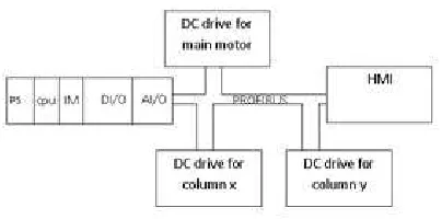
A New Proposed Control Design is shown in
Figure 1, the analogue drives are replaced
with digital drives. The new control panel
will be provided with human machine
interface (HMI). Depeding on the existing
control PLC (programable logic controller)
SIEMENS S7_300 CPU controller with digital
and analogue input output module can be
used.
Figure 1 Block Diagram of the New Control
To facilite the comunication between them
a Profibus can be used. The block diagram
of the new control is shown in figure 1.
PROGRAMMABLE LOGIC CONTROLLER (PLC)
All PLCs have four basic stages of operations
that are repeated many times per second.
Initially when turned on the first time it will
check it’s own hardware and software for
faults. If there are no problems it will copy
all the input and copy their values into
memory, this is called the input scan. Using
only the memory copy of the inputs the
ladder logic program will be solved once,
this is called the logic scan. While solving the
ladder logic the output values are only
changed in temporary memory. When the
ladder scan is done the outputs will updated
using the temporary values in memory, this
is called the output scan. The PLC now
restarts the process by starting a self check
for faults. This process typically repeats 10
to 100 times per second9.
A Profibus Communication system uses a
bus master to poll slave devices distributed
in multi-drop fashion on an RS485 serial
bus. A ProfiBus slave is any peripheral
device (I/O transducer, valve, network
drive, or other measuring device) which
processes information and sends its output
to the master. The slave forms a “passive
station” on the network since it does not
have bus access rights, and can only
acknowledge received messages, or send
response messages to the master upon
request. It is important to note that all
Available Online At www.ijpret.com all network communication originates from
the master 10, 11.
Human Machine Interface (HMI) allow
control systems to be much more
interactive than before. The basic purpose
of an HMI is to allow easy graphical
interface with a process. These devices
have been known touch screens, displays,
Man Machine Interface (MMI) and Human
Machine Interface (HMI)12.
As in all forms of industrial and precision
control, digital implementations have
replaced analogue circuitry in many electric
drive systems but there are few instances
where this has resulted in any real change
to the structure of existing drives. In most
cases understanding how the drive
functions is still best approached in the first
instance by studying the analogue version13.
SYSTEM PROGRAMMING
For programming the system to cope with
the new control, first the inputs and
outputs has to be determined. The inputs
and outputs for one motor are shown in
Appendex (A1). Because there are no
differeces on programming of the three
motor except addresses will be changed.
Second configuration is done with Simatic
Step 7. Some instructions are there to
describe how a MASTERDRIVES drive with
speed control can be coupled to a SIMATIC
S7 CPU. Only the ON/OFF command, the
fault acknowledges and the speed set point
are operated as control commands. Status
word 1 (ZSW1) and the main actual value
are read back as actual values.
First, commissioning must be performed via
terminals or Drive Monitor; the Profibus
communication must be set up afterwards,
i.e. when the drive can already rotate
without problems.
•Insert a MASTERDRIVES from the STEP7
hardware into the Profibus. The Master
drives converters are included as standard
components in the STEP7 hardware.
SIEM8045 is the corresponding General
Station Descrition (GSD) file. All connections
between the bus and the converter are set
up via parameters in the converter.
•Select the telegram type “Standard
telegram 1“or”PPO3“.
•The I/O start addresses specified for this
Available Online At www.ijpret.com (further description is based on I/O address
260).
•Save and compile the created hardware
configuration and load it on the CPU.
•Third program for every motor will be
written in separate function (FC), and then
called in main organization block (OB1).
Because the program for the three motors
is the same except the address, a single
program for one motor is shown in
appendix A2.
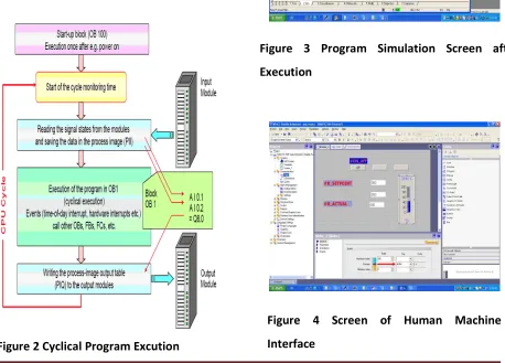
The overall cycle for program excution is
shown in Figure 2.
Figure 2 Cyclical Program Excution
SIMULATIONS
After writing the program and download to
PLC the simulation of the program
execution are shown in Figure 3 & 4.
Figure 3 Program Simulation Screen after
Execution
Figure 4 Screen of Human Machine
Available Online At www.ijpret.com
CONCLUSIONS
In this study, control of double column
vertical machine is done based on
programmable logic controller (PLC). The
original control of the double column
vertical machine was a conventional
control. Through this study Simatic Step
7_300 is used and analogue drives are
replaced with digital drives and control
panel replaced with human machine
interface (HMI). To reduce wiring cable
Profibus Deceterlized Prepherals is used to
communicate between different systems
parts. As a result of successful simulation
program when set point is entered from the
human machine interface the motor tracks
the set point.
REFERENCES
1. T Krairojananan and S Suthapradit, A PLC
Program Generator Incorporating
Sequential Circuit Synthesis Techniques”,
IEEE, APCCAS, 1998: 399-402.
2. K Ji, Y Dong, Y Lee and J Lyoul, Reliability
Analysis Safety Programmable Logic
Controller, SICE-ICASE International Joint
Conference, 2006:18-21.
3. Yasar Birbir and H Selcuk Nogay, (2008)
“Design and Implementation of PLC-Based
Monitoring Control System for Three-Phase
Induction Motors Fed by PWM Inverter”,
International Journal of Systems
Applications, Engineering & Development,
2008; 2(3): 128-135.
4. AR Alae, MM Negm and M Kassas, A PLC
Based Power Factor Controller for a 3-Phase
Induction Motor”, IEEE Transactions on
Energy Conversion, 2000; 2: 1065-1071.
5. MG Ioannides, Design and
Implementation of PLC-Based Monitoring
Control System for Induction Motor, IEEE
Transactions on Energy Conversion, Vol.
2004; 19(3): 469-476.
6. John R Hackworth and Frederick D
Hackworth, Programmable Logic
Controllers: Programming Methods and
Applications, Prentice Hall. 2003.
7. Ahmed Kajala, Double Column Lathe
Vertical Machine PLC based" M.Sc. Thesis in
Electrical Engineering Department SUST,
2011.
8. Hans Berger, Automating with SIMATIC
Available Online At www.ijpret.com 300/400, German, second revised editon,
2003.
9. LA Brayn, EA Brayn, Programmable
Controllers Theory and Implementation,
United State. 1997.
10.Acromag, Introduction to Profibus DP,
2002, www.acromag.com.
11.PROFIBUS Working Group, Specification
for PROFIBUS Device Description and Device
Integration”, Vol. 1, Version 5.1, 2008.
www.profibus.com.
12.Hugh Jack, Automating Manufacturing
systems with PLCs.2004
13.Austin Hughes, Electric Motors and
Drives Fundamentals, Types and