Organized by G. V. S. E. T., Jaipur. Available Online at www.ijpret.com235
INTERNATIONAL JOURNAL OF PURE AND
APPLIED RESEARCH IN ENGINEERING AND
TECHNOLOGY
A PATH FOR HORIZING YOUR INNOVATIVE WORK
ANALYSIS AND CALCULATION OF TRANSFORMER INRUSH CURRENT: A REVIEW
ATUL SONI 1, ANUSHIKHA SHARMA 2, DR. NAGENDRA KUMAR SWARNKAR3
1.Electrical Engineering Department, Suresh Gyan Vihar University, Jaipur 2.Electrical Engineering Department, Suresh Gyan Vihar University, Jaipur
3.Prof. & HOD, Electrical Engineering Department, Suresh Gyan Vihar University, Jaipur
Accepted Date: 19/03/2018; Published Date: 01/04/2018
Abstract: An inrush current is a transient current with high amplitude that may occur when a transformer is energized under no load or lightly loaded conditions. The magnitude of inrush current may be as high as ten or more times of transformer rated current. This results in huge mechanical and thermal stresses on transformer and also inadvertent operation of the protective relay systems. This paper represents the effects of some factors on the inrush current of transformers. This paper discusses about the effects of switching angle variation, the energizing circuit impedance and the remanent flux on the characteristics of inrush current. The results clearly show that increasing circuit resistance or switching angle will decrease inrush current amplitude. Also, it is concluded that for reducing inrush current, appropriate switching angle with respect to the remanent flux must be selected. The results can be used for a better understanding of the inrush current characteristics and proper actions of the protective system.
Keywords: Inrush current, Switching Angle, Adaptive Neuro-Fuzzy Inference System (ANFIS), Remanent Flux
Corresponding Author: ATUL SONI
Access Online On:
www.ijpret.com
How to Cite This Article:
Atul Soni, IJPRET, 2018; Volume 6 (8): 235-244
PAPER-QR CODE
SPECIAL ISSUE FOR
NATIONAL LEVEL CONFERENCE
Organized by G. V. S. E. T., Jaipur. Available Online at www.ijpret.com236 INTRODUCTION
A Power transformers are most essential and critical part of power system networks and are the most expensive and vital equipment in substations of electric power systems. Power System reliability is determined by thorough knowledge of transformer’s performance under various operating conditions. To maintain the power supply quality and reliability, the major issue which has to take into consideration is Transformer Energization.
Energization of unloaded transformers results in magnetizing inrush current (IC) with high amplitude due to non-linear magnetic property of transformer core. The high non-linearity of the iron core results into a current waveform full of harmonics. The typical harmonic content of a transformer inrush current waveform includes 62 % of 2nd harmonic and 55% of DC component of fundamental power frequency.
These currents have various unfavorable effects, including operation failure of transformer differential protection, deterioration of the insulation and mechanical support of windings and reduced power quality of the system.
Because the amplitude of inrush current can be as high as a short circuit current, a detailed analysis of the magnetizing inrush current under various conditions is necessary for the concerns of a protective system for the transformers.
To avoid mal-operation of protection system due to magnetizing inrush current, many researches are conducted for the discrimination of inrush current from internal fault currents. Pre-insertion of series resistors and synchronous closing of circuit breakers are examples of the available mitigation techniques [7]. A neutral resistor based scheme for mitigating inrush currents was proposed in some papers.
FUNDAMENTALS OF INRUSH CURRENT
It is known that a transformer will experience magnetizing inrush current during energization. Inrush current occurs in a transformer whenever the residual flux does not match the instantaneous value of the steady-state flux which would be required for the particular point on the voltage waveform at which the circuit is closed.
Transformer Inrush current is classified into three types:
a) Initial Inrush Current: This type of the inrush current occurs when the transformer is switched-on to the supply.
Organized by G. V. S. E. T., Jaipur. Available Online at www.ijpret.com237
c) Sympathetic Inrush Current: This type of the inrush current is an unusual event, but occurs when a transformer is connected in parallel with a second energized transformer.
For the explanation of the mechanism of causing inrush current in a transformer’s primary winding when connected to an AC voltage source, where λ and v are the instantaneous flux in a core and voltage drop across the primary winding, respectively
V=
The general equation of the amplitude of inrush current as a function of time can be expressed as:
Where,
Vm- Maximum applied voltage
Zt- Total impedance under inrush, including system
- Energization angle, t- time, to- point at which core saturates
- Time constant of transformer winding under inrush conditions - Function of t.
Kw- Accounts for 3 phase winding connection Ks- Accounts for short-circuit power of network
FACTORS AFFECTING INRUSH CURRENT
For designing a protective system for transformer, the peak value of inrush current is an important factor. In these cases, a simple equation can be used to calculate the peak value of the first cycle of the inrush current. This equation is as given below:
Where,
Vm- Maximum applied voltage
L- Air core inductance of the transformer R- Total dc resistance of the transformer
Organized by G. V. S. E. T., Jaipur. Available Online at www.ijpret.com238
As from the equations, the value of inrush current is depends on the parameters of transformer and operating conditions. So, a detailed and calculative analysis for finding the relation between the inrush current characteristics and these factors are needed.
METHODS OF REDUCTION OF INRUSH CURRENT
As there are certain parameters that affects the transformer’s magnetizing inrush current. The effects on magnetizing inrush current by varying those parameters are discussed by a comparative study of different methods such as using MATLAB Simulink, Adaptive Neuro-Fuzzy Inference System (ANFIS) and JAVA.
A.EFFECTS OF DIFFERENT SWITCHING ANGLE
In this section, the effect of switching angle variation on the characteristics of inrush current has been analyzed. The remanent flux (Br) for all switching angles is 0.826 Weber-coil. Also the source resistance has been taken to zero. Fig. 1 shows that by different switching angles (θ), the amplitude of inrush current changes accordingly. As the figure shows, the maximum amplitude of inrush current is at 0° that is 5.52A.[2] Also, it shows that the increased value of the switching angle will decrease the amplitude of inrush current and its second harmonic.
Fig. 1- Variation in the amplitude of inrush current by changing switching angle
Organized by G. V. S. E. T., Jaipur. Available Online at www.ijpret.com239 Fig. 2- Variation of 2nd harmonic of phase (A) current with time at different switching angle
Although the amplitude of inrush current has been decreased, but second harmonic first increased and then decreased.
B. EFFECTS OF SOURCE RESISTANCE
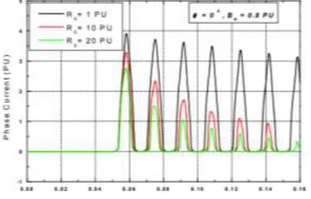
In this case, the switching angle (θ) is 0. Also, the remanent flux (Br) is the same as the previous part. The effects of source resistance have been considered by increasing Rt. Fig. 3 shows the effect of source resistance on the amplitude of inrush current. From the figure, the maximum amplitude of inrush current is at Rs = 1 PU. Also, it shows that the increment in source resistance will decrease the amplitude of inrush current and its second harmonic. Therefore, we can say that transformers located nearer to the generating plants shows higher amount of inrush currents, which lasted much longer than the transformer installed electrically away from generator.
Fig. 3- Variation in the amplitude of inrush current by changing source resistance
Organized by G. V. S. E. T., Jaipur. Available Online at www.ijpret.com240 Fig. 4- Variation of 2nd harmonic of phase (A) current with time at different source resistance
C. EFFECTS OF THE REMANENT FLUX
The effect of remanent flux on the first cycle peak current at different switching angles is shown in Fig. 5. As from figure, the first cycle peak current has large change when the remanent flux varies. Also the result indicates that switching at θ=90 or Br=0 may not necessarily reduce the magnitude of inrush current.[4] So, for reducing inrush current, an appropriate switching angle by considering remanent flux must be selected.
Fig. 5- Variation of inrush current of phase (A) with time at different remnant flux
Organized by G. V. S. E. T., Jaipur. Available Online at www.ijpret.com241 Fig. 6- Variation of 2nd harmonic of phase (A) current with time at different remnant flux
V IDENTIFICATION OF INRUSH CURRENT
It is noted that the equations of the transformer inrush current and its second harmonics are nonlinear, resulting in a complex mathematical model. As it is desired to reach the amplitude of inrush current and its second harmonics accurately and fast, due to change in the transformer’s operating conditions.
For this there are different methods to find out the magnitude and intensity of magnetizing inrush current.
A.ADAPTIVE NEURO-FUZZY INFERENCE SYSTEM
Adaptive Neuro-Fuzzy Inference System (ANFIS) is a hybrid intelligent system which is a combination of fuzzy inference system with neural network. To deal with linguistic expressions understandable to human experts (if-then) rules and the ability of being trained by samples of input-output data are the main advantages of ANFIS.
The ANFIS model is based upon a first order Takagi–Sugeno model five-layer architecture [5]. ANFIS is much more complex than the fuzzy inference systems, and is not available for all of the fuzzy inference system options. An error occurs if FIS structure does not comply with some constraints, one of these constraints is ANFIS has a single output, obtained using weighted average defuzzification [5]. So, two ANFIS networks can be used for a two outputs (Peak inrush current and its second harmonic) system working in parallel with the same inputs patterns.
In the first layer of the two models, the Switching angle (θ), supply resistance (Rs), and remnant flux BR, multiplied by respective weights, are each mapped through three fuzzy logic membership functions. With RMSE = 0.018376.
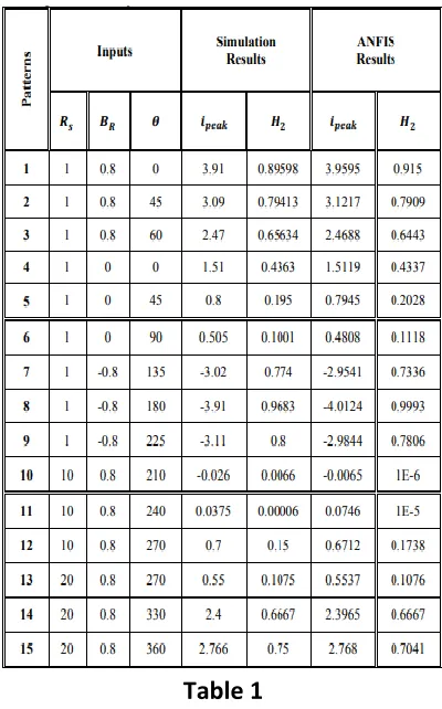
Organized by G. V. S. E. T., Jaipur. Available Online at www.ijpret.com242 Table 1
In the third layer, normalize the rules firing strengths.
In the fourth layer, compute the contribution of each rule towards the overall output.
In the fifth layer, compute the overall output as the summation of contribution from each rule. A hybrid learning algorithm that combines the gradient method and the least squares is estimated to learn parameters [6].
It has been computed for each applied proposed technique. Table (1) depicts a comparison between the different computed data and estimated data by the ANFIS algorithms for transformer inrush current. It is clearly shown from the results obtained that the ANFIS presents good agreement with data obtained results obtained by Simulink for each signal tried before.
B. JAVA (Java 2 SDK, SEv1.8.0_60)
Organized by G. V. S. E. T., Jaipur. Available Online at www.ijpret.com243
1. Calculates the peak value of inrush current for individual cycles and plot them on a graph, that providing inrush current envelope.
2. Calculates the effect of switching angle on the peak value of inrush current.
3. Calculates the magnitude of harmonics of different orders generated due to inrush current and determines total harmonic distortion (THD) due to inrush current.
CONCLUSION
In this paper, the effects of some parameters on the characteristics of inrush current are investigated by a comparative study of MATLAB Simulink, JAVA (Java 2 SDK, SEv1.8.0_60) and ANFIS.
Results show that increasing switching angle at a positive remanent flux or source resistance will decrease the amplitude of inrush current. It also shows that largest second harmonic content may not necessarily appear at the first cycle. The effect of remanent flux on the peak current of the first cycle shows that it has great changes when the remanent flux changes. It also has been concluded that for reduction of inrush current, an appropriate switching angle by considering remanent flux, must be selected.
ANFIS Model has beauty to train network with data of non-linearity which gives exact matching with target values. Therefore, ANFIS model is able to predict maximum inrush current value with an acceptable average of percentage error and second harmonic current content again with an acceptable average percentage error.
REFERENCES
1. G. Baoming, A. T. Almeida, Z. Qionglin and W. Xiangheng, An Equivalent Instantaneous Inductance-Based Technique for Discrimination Between Inrush Current and Internal Faults in Power Transformers, IEEE Trans. on Power Delivery, Vol. 20, No. 4, October 2005.
2. P. Ganapathi and, K. Bharanidharan, "ANN based Discrimination of Inrush Current and Fault Current in Power Transformer", International Electrical Engineering Journal (IEEJ)Vol. 5 (2014) No.4, pp. 1328-1334
3. M. Jamali, M. Mirzaie, and S. Asghar Gholamian, "Calculation and Analysis of Transformer Inrush Current Based on Parameters of Transformer and Operating Conditions", Electronics and Electrical Engineering, Vol. 109, No.3 2011, pp. 17 – 20.
4. Steurer, M., Frohlich, K., "The Impact of Inrush current on the Mechanical stress of High voltage Power Trasformer Coils, "IEEE Transactions on Power Delivery, Volume 17, Issue: PP. 155 – 160," an 2002.
Organized by G. V. S. E. T., Jaipur. Available Online at www.ijpret.com244
6. Puneet Kumar Singh, and D.K. Chaturvedi, "Neural Network based Modeling and Simulation for Estimation of Maximum Transformer Inrush Current", International Journal of Computer Applications, Volume 123 – No.5, August 2015.