Available Online at www.ijpret.com 268
INTERNATIONAL JOURNAL OF PURE AND
APPLIED RESEARCH IN ENGINEERING AND
TECHNOLOGY
A PATH FOR HORIZING YOUR INNOVATIVE WORK
BUSBAR PROTECTION USING FAULT DETECTION ALGORITHM.
MS. KALYANI J. LADHAKE1, MR. S. A. BORAKHADE2.
1. Electrical Engineering Department, M. E. Scholar, Sant Gadge Baba Amravati University.
2. Electrical Engineering Department, Faculty of Electrical Engineering, Sant Gadge Baba Amravati University. Accepted Date: 05/03/2015; Published Date: 01/05/2015
\
Abstract: This paper includes busbar protection using fault detection algorithm. The
protection system is suitable for the protection of multiple busbar arrangements. The method of Symmetrical component is a powerful tool for analysis of unsymmetrical faults. Hence we are using criterion function ‘R’ whose value is derived from symmetrical components of current will decide balanced and unbalanced condition of electrical power system. It will improve the fault performance of the entire network. The capability of method is demonstrated by simulating 4 bus power system for unbalanced faults and switching cases.This paper also reviews different types of fault on power system.
Keywords: Busbar, Fault Detection Algorithm, Symmetrical Component, R Criterion,
Transformer energizing.
Corresponding Author: MS. KALYANI J. LADHAKE
Access Online On:
www.ijpret.com
How to Cite This Article:
Kalyani J. Ladhake, IJPRET, 2015; Volume 3 (9): 268-274
Available Online at www.ijpret.com 269 INTRODUCTION
The stability of the system is affected by the fault. A fault is abnormal system condition, which is in most cases is short circuit, and occurs as a random event. Faults which occur on a power system are broadly classified as symmetrical and unsymmetrical fault. A three phase fault is called symmetrical type fault. In a three phase all the three phases are short circuited with or without involving ground. There are mainly three types of unsymmetrical (unbalanced) faults– single line-to-ground (L-G) fault, line-to-line (L-L) fault, and double line-to-ground (LL-G) fault.
Identification of those factors which are responsible for undesirable operation of system is very important. Power system switching such as motor starting and transformer energizing is the most important source of undesirable operation of protective scheme. There are various ways for reducing starting current of induction motor theoretically. But in practice there are some factors which make it impossible to reduce distortion of current waveform. Hence it is necessary to introduce a method that discriminates switching case from fault case (Saeed Lotfi-fard, 2007).
When the system is unbalanced the voltages, currents and the phase impedances are in general unequal such a system can be solved by a symmetrical per phase technique known as method of symmetrical component. We are using symmetrical component to determine fault and non-fault condition of the system. The value of criterion function ‘R’ is calculated from symmetrical component. It will formulate an algorithm based on different behavior of current components during fault and non-fault conditions.
METHODOLOGY
Any three-phase voltage and current consist of three components in sequence space. The equation showing relation between three-phase current and their symmetrical component can be expressed in matrix form as:
Available Online at www.ijpret.com 270 Ia, Ib, Ic are the phase currents of phase a, b, c, and I0, I1, I2 are zero, positive, and negative sequence components respectively. From above equation we can obtain symmetrical component from phase current. Currents Ia, Ib, and Ic are balanced means that 1+a+a =0. So existence of the negative components means that the system is unbalanced.
Major feature of unsymmetrical faults is the large value of the negative component.
For line to ground fault,
Where Zf is the fault impedance between the line and ground, Z0 is the zero component impedance, Z1 is the positive component impedance, and Z2 is the negative component impedance. Similarly,
For line to line fault,
For line-line-ground fault,
The concept of criterion function R is defined as follows:
Available Online at www.ijpret.com 271 Referring above equations and considering Zf =0, Z2=Z0, In case of unsymmetrical fault, R is less than 0.35. It indicates fault condition. Symmetrical fault occurs rarely as compared to unsymmetrical fault and has negligible negative sequence component similar with the switching case. Hence in the switching case R is close to 1. It indicates non-fault condition.
SIMULATION RESULTS
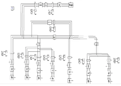
To illustrate an implementation of fault detection algorithm for busbar protection, we use a typical bus arrangement, as shown in Figure 1 There are four buses (BUS1, BUS2, BUS3, and BUS4) and eight terminals (TM1, TM2,.., TM8). We are giving name BUS1 as ZONE1, BUS2 as ZONE2, BUS3 as ZONE 3, and BUS4 as ZONE4. We have three disconnect switches (only disconnects linking busbars are shown). DS1 connects BUS1 and BUS3, DS2 connects BUS1 and BUS2, and DS3 connects BUS3 and BUS4.
Figure 1 Illustration of a bus arrangement with four buses and eight terminals.
Figure 2 Simulink model for four bus system.
Available Online at www.ijpret.com 272 34.5kV/10.5kV for distribution. Here we present simulation results for following fault and non-fault cases:
Case 1: Transformer energizing
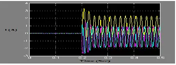
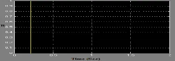
Various inrush current conditions were simulated at different terminals of busbar in power system to study transformer energizing. Transformer is switched at terminal 5 of busbar 2 at instant t=0.2s and three phase currents are measured at busbar 2. Figure 3 shows three phase currents. Figure 4 shows the value of R is close to 1 and larger than 0.35. It indicates the non-fault case.
Figure 3 Three phase current due to transformer energizing.
Figure 4 Value of R versus time due to transformer energizing
Case 2: Motor starting
A 2 MVA induction motor is switched at t = 0.2s at terminal 5 of busbar 2 and three phase currents are measured at busbar 2. Figure 5 shows three phase currents. Figure 6 shows the value of R is close to 1 and larger than 0.35. It indicates the non-fault case. In this case tripping signal is prevented.
Available Online at www.ijpret.com 273 Figure 6 Value of R versus time due to motor starting.
Case 3: Unsymmetrical fault (Line to ground fault)
A line to ground fault with phase ‘a’ is occur at terminal 8 of busbar 4 at instant t=0.3s and three phase currents are measured at busbar 4. Figure 7 shows three phase currents. Figure 8 shows the value of R is close to 0 (that is less than 0.35). It indicates the fault case in which relay operates to isolate faulty system from healthy system.
Figure 7 Three phase current due to fault L-G
Figure 8 Value of R versus time due to fault L-G
Case 4: Simultaneous fault and switching case (Simultaneous transformer energizing and Line to line fault)
In this case, transformer is switched on at terminal 5 of busbar 2 at t= 0.2s and at the same instant line to line fault (A-B) occurs. Three phase currents are measured at busbar 2. Figure 9 shows three phase currents. Figure 10 shows the value of R is close to 0 (that is less than 0.35). It indicates the fault case in which relay operates to isolate faulty system from healthy system.
Available Online at www.ijpret.com 274 Figure 9 Three phase current due to fault (A-B) and transformer energizing.
Figure 10 Value of R versus time due to fault (A-B) and transformer energizing.
CONCLUSION
The simulation results show that symmetrical component can improve protection system performance. By using negative sequence current component, the concept of criterion function ‘R’ is introduced. The suggested criterion is independent of amplitude of current which is advantageous. Reliability of the system can improve.
REFERENCES
1. D. P. Kothari and I. J. Nagrath, Power System Engineering, The McGraw Hill companies, second edition.
2. Armando Guzmán, Bai-Lin Qin, Casper Labuschagne, Reliable Busbar Protection with Advanced Zone Selection, IEEE vol. 20, No. 2, April 2005.
3. Saeed Lotfi-fard, Jawad Faiz, and Reza Iravani, Improved Overcurrent Protection Using Symmetrical Components, IEEE. vol. 22, No. 2, April 2007.
4. H. T. Seeley and F. V. Roeschlaub, Instantaneous Bus-differential Protection Using Bushing Current Transformers, AIEE Trans., vol. 67,pp.1709–1718,1948.