Available Online at www.ijpret.com 272
INTERNATIONAL JOURNAL OF PURE AND
APPLIED RESEARCH IN ENGINEERING AND
TECHNOLOGY
A PATH FOR HORIZING YOUR INNOVATIVE WORK
CRACK DETECTION TECHNIQUES IN ROTATING SHAFT
GAURAV S. CHAURE1, DEVENDRA Y. SHAHARE2
1. M tech scholar, Department of Mechanical Engineering, Yeshwantrao Chavan College of Engineering, Nagpur, India. 2. Asst. Professor, Department of Mechanical Engineering, Yeshwantrao Chavan College of Engineering, Nagpur, India.
Accepted Date: 05/03/2015; Published Date: 01/05/2015
\
Abstract: Rotating machines are susceptible to fatigue failures if transverse cross sectional
cracks form in the shaft. The failure of shaft results in major catastrophic events and the economic losses associated with these shaft failures are substantial. To addresses the shaft cracking issue, various crack detection techniques are developed in past two decades. There are several researches and investigations are carried out for detection of crack in the rotating shaft at the early stages. This paper comprises the literature review on various crack detection techniques, diagnostics and different faults occurs in rotating shafts.
Keywords: Torsional vibration, Acoustic Emission, Active Sensing, Motor Current Signature.
Corresponding Author: MR. GAURAV S. CHAURE
Access Online On:
www.ijpret.com
How to Cite This Article:
Gaurav S. Chaure, IJPRET, 2015; Volume 3 (9): 272-278
Available Online at www.ijpret.com 273 INTRODUCTION
Shafts are components subjected to critical operating conditions in high performance rotating equipment such as compressors, electric motors, steam and gas turbines, pumps and generators that are used in process and utility plants. There are several reasons for shaft failures which include metallurgical abnormalities, cyclic fatigue, excessive torque and increased stress due to misalignment, impacting and most commonly the fatigue failure caused by transverse cross sectional cracks. Cracks are defined as any unintentional discontinuities in the shaft material. Once the cracks are initiated in a shaft it results into unpredictable failure of the shaft without any warning which further results into the catastrophic failure of the equipment. Cracks are initiated as tiny discontinuities in elastic material such as low/medium alloy steels that are used for manufacturing turbo machine shafts, further they grow in size as the shaft is subjected to cyclic stresses and results into total failure of the shaft. Hence if the cracks are detected at their initial stages before they reaches to critical size the total failure of the component can be prevented. The next section includes the types and causes of the cracks followed by review of the literature on crack detection techniques. The cracking of shafts occurs due to high and low cycle fatigue, or stress corrosion. A typical arrangement of events leading to total failure of component by cracking in a ductile material is as follows.
Crack initiation. In the un cracked parent material tiny discontinuities are initiated at this stage. There are many causes of crack initiation which ultimately results into the stress concentration like mechanical stress raisers, such as sharp keyways, dents and grooves, intense shrink fits, unexpected cross-sectional changes and many manufacturing defects.
Crack propagation. During this stage, the crack grows in size due to the cyclic stresses induced in the component.
Failure. Failure of the material occurs when the material that has been affected by the crack cannot withstand the applied loads. The actual failure of the material can be in a brittle or ductile manner, depending on the prevailing conditions. Failure occurs very rapidly once the crack(s) reaches a critical size. According to the geometries of cracks they can be broadly classified as follows [1, 2]
• When the propagation of cracks is perpendicular to the shaft axis they are known as “transverse” cracks.
• Cracks that are parallel to the shaft axis are known as “longitudinal” cracks.
Available Online at www.ijpret.com 274 • “breathing” cracks are those which opens when the affected part of the material is subjected to tensile stresses and closes when the stress is reversed i.e. at compressive stress.
• Cracks that always remain open are known as “gaping” cracks. They are more correctly called “notches”.
• Cracks that open on the surface are called “surface” cracks.
• Cracks that do not show on the surface are called “sub-subsurface” cracks.
II. LITERATURE REVIEW
In this literature various techniques of crack detection are discussed.
Torsional Vibration Analysis.
Acoustic Emission, Vibration and Motor Current Signature Analysis.
Active Sensing Simulation.
Lateral and Torsional vibration measurements and analysis
Torsional Vibration Analysis:
Martin Trethewey, Mitchell S. Lebold, developed the system for the crack detection in rotating components. They used an approach which utilizes torsional vibration signature analysis. As soon as the initiation and propagation of cracks occurs, the reliability of rotating components degrades due to this, the torsional natural frequencies decreases. Therefore, the tracking of torsional natural frequencies can be used as a health diagnostic feature in rotating machinery [3,4]
Available Online at www.ijpret.com 275 Torsional natural frequencies are sensitive to crack growth. Hence it is considered as preferred feature in the analysis. Since torsional natural frequencies decreases as a crack grows, the modal parameters may be used as diagnostics to monitor crack growth. A simulation-based probabilistic approach was adopted for the analysis. The analysis shows the following results.
A quantifiable decrease in torsional rigidity was correlated with crack growth.
A decrease in first torsional natural frequency was observed as the crack grew.
Changes in natural frequency in the range of 0.1 to 0.2 Hz were identifiable by visual inspection of the spectrum.
Acoustic emission, Vibration and Motor Current Signature Analysis:
Babak Eftekharnejad, A. Addali, D. Mba combined acoustic emission, vibration and motor current signature and concluded that the combination of these methods could recommend good diagnostic information. They conducted the experiments on the gearbox suffered through shaft failure. Various sensors are used to get adequate information.
The below diagram shows the schematic representation of gearbox and sensor arrangement
[6].
Fig. 2: Schematic view of the gearbox and sensor arrangement [6].
The conclusions taken out are:
Available Online at www.ijpret.com 276 correlation with increasing surface damage until after the wavelet decomposition was undertaken.
Active Sensing Simulation:
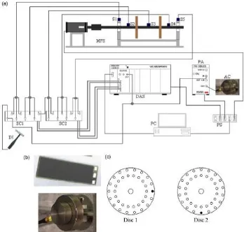
Jose M. Macharo, Douglas Admas created an apparatus which is physics based three-dimensional model of an experimental machinery fault simulator using ANSYS with beam element based on Timoshenko beam theory. The experimental and numerical analysis showed that when a transverse crack appears in the shaft of system the variation in natural frequency and the mode shapes are negligible; therefore it is necessary to use active sensing to detect the damage [6].
Fig. 3: (a) Connection of diverse devices used: MFS-Machinery Fault Simulator; S-Sensor; SC-signal conditioner; DAS-data acquisition system; PA-power amplifier; IH-impact hammer;
AC-actuator; PS-power source; PC-personal computer. (b) Piezoelectric actuators. (c) Mass imbalance locations seen from the motor.[6]
Both online and offline tests with or without actuators were carried out.
Available Online at www.ijpret.com 277 Lateral and Torsional vibration measurements and analysis:
A. Tlaisi, A. Akinturk, A. S. J. Swamidas & M. R. Haddara did the research in cracking of cylindrical shafts. They carried out the experimental and numerical investigations to identify the presence of crack in a cylindrical overhanging shaft with a propeller at free end. Different cracks of different depths are located at maximum bending moment positions and the lateral and torsional vibration parameters were studied.
Fig. 4: Line diagram of the experimental setup.[7]
Commercial FE software ANSYS Workbench 13 was utilized to carry out the modelling and frequency analysis of circular shafts supported on bearings. Both the Finite Element Analysis and experimentation program gave the eight lowest bending frequencies and mode shapes of the un-cracked and cracked shafts. They concluded that it is possible to detect the presence of crack in a rotating shaft above a crack depth ratio of 0.2 when the rates of changes of bending or torsional frequencies are plotted as a function of crack depth ratio.
III. CONCLUSION
A comprehensive review of various crack detection techniques has been attempted. Newer techniques are emerging as further insight is gained in the fields of fracture mechanics, simulation and condition monitoring. The future points to a flexible, multidisciplinary and robust detection methodology for different types of rotors. This will go a long way to increasing the overall reliability and safety of rotating machinery in general.
REFERENCES
Available Online at www.ijpret.com 278 2. Fuchs, H. O. and Stephens, R. I., 2000, “Metal fatigue in Engineering”, 2nd Ed., Wiley, New York.
3. Mitchell S. Lebold, Martin Trethewey, Kenneth Maynard, “Using Torsional Vibrations Analysis as a synergistic method for crack detection in rotating equipment”, Journal of Sound and Vibration. 2004.
4. Martin Trethewey, Mitchell Lebold,” A Spectral simulation approach to evaluate probabilistic measurement preccision of a reactor coolant pump torsional vibration monitoring system.” Journal of Sound and Vibration 2008; 310: 1036-56.
5. Babak EfteKharnejad,A. Addali, D. Mba, ”Shaft crack diagnostics in a gearbox”, Applied Acoustics 73 (2012) 723-733.
6. Jose M. Machorro-Lopez , Douglas E. Adams, Julio C. Gomez-Mancilla, Kamran A. Gul “Identification of damaged shafts using active sensing simulation and experimentation”, Journal of Sound and Vibration 327 (2009).
![Fig. 1: Torsional vibration measurement instrumentation [4].](https://thumb-us.123doks.com/thumbv2/123dok_us/8726839.1745435/3.612.229.395.527.619/fig-torsional-vibration-measurement-instrumentation.webp)
![Fig. 2: Schematic view of the gearbox and sensor arrangement [6].](https://thumb-us.123doks.com/thumbv2/123dok_us/8726839.1745435/4.612.206.409.417.558/fig-schematic-view-gearbox-sensor-arrangement.webp)
![Fig. 4: Line diagram of the experimental setup.[7]](https://thumb-us.123doks.com/thumbv2/123dok_us/8726839.1745435/6.612.195.419.201.296/fig-line-diagram-experimental-setup.webp)
