by
Samer Yousef Khamaiseh
A thesis
submitted in partial fulfillment of the requirements for the degree of Master of Science in Computer Science
Boise State University
© 2016
DEFENSE COMMITTEE AND FINAL READING APPROVALS
of the thesis submitted by
Samer Yousef Khamaiseh
Thesis Title: Security Testing with Misuse Case Modeling Date of Final Oral Examination: 05 October 2016
The following individuals read and discussed the thesis submitted by student Samer Yousef Khamaiseh, and they evaluated his presentation and response to questions during the final oral examination. They found that the student passed the final oral examination.
Dianxiang Xu, Ph.D. Chair, Supervisory Committee Jyh-haw Yeh, Ph.D. Member, Supervisory Committee Jidong Xiao, Ph.D. Member, Supervisory Committee
iv
v
This research and experience were possible because I have had the extraordinary advice and assistance of my supervisor Dr. Dianxiang XU. Dr. XU has provided me with critical experience as a graduate student in my desire to be a scientific researcher in the future. Dr. XU’s advice, help, and guidance have provided me space and trust that any effective researcher needs in order to be successful.
I also, emphatically and truly, wish to thank my parents, Yousef and Amenah, for their unlimited support, encouragement, and assistance throughout my lifetime. They have always told me that I can accomplish anything that I have set out to achieve. My parents have also taught me to be patient and committed into what I endeavor to accomplish. My parents are the main reason for any personal success that I have had and that I will have in the future. Many thanks to my sisters and brothers for their help and unlimited willingness to maintain their support and interest in my studies abroad.
Many thanks to Dr.Izzat Al-Smadi for his help and support throughout my studies. Dr. Izzat has engendered in me the basic requirements of being an effective researcher. Special thanks go to my friends Zaid Al-Omari and Tom Gabel for standing with me through this process, for providing unlimited help, support, and encouragement, and that they have always trusted in my capabilities in combination with pushing me to achieve my goals.
vi
Having a comprehensive model of security requirements is a crucial step towards developing a reliable software system. An effective model of security requirements which describes the possible scenarios that may affect the security aspects of the system under development can be an effective approach for subsequent use in generating security test cases.
Misuse case was first proposed by Sinder and Opdahl as an approach to extract the security requirements of the system under development [1]. A misuse case is a use case representing scenarios that might be followed by a system adversary in order to compromise the system; that is a behavior that should not happen in a system.
As an effective approach used to model potential threats to the system under development, misuse cases are an effective approach for suggesting mitigation mechanisms. A mitigation use case is a use case that represents the countermeasure requirements of a misuse case.
vii
Unfortunately, this approach has difficulties and limits the ability to generate security test cases from the misuse cases and mitigation use cases. This thesis presents a new, structured approach to generating security test cases based on the extracted security test model from the textual description of the misuse cases accompanying mitigation use cases, represented as a Predicate/Transition (PrT) net.
This approach will enable the system developers to model the misuse cases accompanying mitigation use cases and then generating security test cases based on the resulting security test models, ensuring that the potential attacks are mitigated appropriately in the software development process.
viii
SECURITY TESTING WITH MISUSE CASE MODELING ... i
DEDICATION ... iv
ACKNOWLEDGEMENTS ...v
ABSTRACT ... vi
TABLE OF CONTENTS ... viii
LIST OF TABLES ... xvii
LIST OF FIGURES ... xxii
LIST OF ABBREVIATIONS ...xxv
CHAPTER ONE INTRODUCTION ...1
1.1 Background ...1
1.2 Problem Statement ...2
1.3 Objectives ...3
1.4 Thesis Organization ...4
CHAPTER TWO RELATED WORK ...5
CHAPTER THREE THE APPROACH ...9
3.1 Misuse Case Modeling ...10
3.1.1 Defining Use Cases ...10
3.1.2 Defining Misuse Cases ...12
ix
3.2.1 Transforming Misuse Case Textual Description into PrT Net ...18
3.2.2 Transforming Mitigation Use Case into PrT Constructs. ...25
3.2.3 Combine Misuse Case and Mitigation Use Case into PrT Constructs ...26
3.3 Combine Security Test Models. ...27
3.3.1 Combine Security Test Models Based on STRIDE ...28
3.3.2 Combine Security Test Models Based on Use Case. ...30
3.4 Generate Security Test Cases...32
CHAPTER FOUR CASE STUDY I: FILEZILLA FTP SERVER ...34
4.1 Misuse Case Modeling ...34
4.1.1 Defining FileZilla FTP Server Use Cases ...34
4.1.2 Defining FileZilla FTP Server Misuse Cases ...36
4.1.3 Defining FileZilla FTP Server Mitigation Use Cases ...38
4.2 Create Security Test Model ...39
4.3 Generate Security Test Cases...41
4.4 Evaluation of Security Test Cases. ...41
CHAPTER FIVE CASED STUDY II: GRANT PROPOSAL MANAGEMENT SYSTEM (GPMS) ...49
5.1 Misuse Case Modeling ...49
5.1.1 Defining GPMS Use Cases ...49
5.1.2 Defining GPMS Misuse Cases ...52
5.1.3 Defining GPMS Mitigation Use Cases ...54
x
5.4 Evaluation of Security Test Cases. ...59
CHAPTER SIX CONCLUSIONS ...74
6.1 Results Analysis ...74
6.2 Future Work ...76
REFERENCES ...78
APPENDIX A CASE STUDY 1: FILEZILLA SERVER MISUSE CASE MODELING DATA ...81
A.1 FileZilla Server Use Cases ...82
A.1.1 FileZilla FTP Server Uploading Files Use Case Description ...82
A.1.2 FileZilla FTP Server Delete File/Directory Use Case Description ..83
A.1.3 FileZilla FTP Server Create Directory Use Case Description ...84
A.1.4 FileZilla FTP Server Download Files Use Case Description ...85
A.1.5 FileZilla FTP Server Login Description ...86
A.1.6 FileZilla FTP Server Rename Files/Directories Use Case Description ...87
A.1.7 FileZilla FTP Server Append Files Use Case Description ...88
A.1.8 FileZilla FTP Server List Directories Use Case Description ...89
A.1.9 FileZilla FTP Server List Subdirectory Use Case Description ...90
A.1.10 FileZilla FTP Server Logout Use Case Description ...91
A.1.11 FileZilla FTP Server List System Features Use Case Description 91 A.2 FileZilla Server Misuse Cases...92
A.2.1 Unauthorized Access/Modify Files Misuse Case Description ...92
xi
A.2.4 Injecting Malicious Code Misuse Case Description ...94
A.3 FileZilla Server Mitigation Use Cases ...95
A.3.1 Validate User Input Mitigation Use Case Description...96
A.3.2 Validate User Permission Mitigation Use Case Description ...96
A.3.3 Auto Ban IP Address Mitigation Use Case Description ...97
A.4 FileZilla Server Security Test Models Based on Use Case Technique ...98
A.4.1 Uploading Files Use Case Security Test Model ...98
A.4.2 Delete File\Directory Use Case Security Test Model ...98
A.4.3 Create Directory Use Case Security Test Model ...99
A.4.4 Download Files Use Case Security Test Model...99
A.4.5 FileZilla FTP Server Login Use Case Security Test Model ...100
A.4.6 Rename Files\Directories Use Case Security Test Model ...101
A.4.7 Append Files Use Case Security Test Model...101
A.4.8 List Directories Use Case Security Test Model ...102
A.4.9 List Subdirectory Use Case Security Test Model ...102
A.4.10 FileZilla FTP Server Logout Use Case Security Test Model ...103
A.4.11 List System Features Use Case Security Test Model ...103
A.5 FileZilla Server Security Test Models Based on STRIDE Technique ...104
A.5.1 Denial of Service Category Security Test Model ...104
A.5.2 Privilege Elevation Category Security Test Model...105
A.5.3 Spoofing Category Security Test Model ...105
xii
B.1.1 Signup a New User Use Case Description ...107 B.1.2 Create a New Proposal Document Use Case Description ...108 B.1.3 Submit a Proposal by Principal Investigator (PI) Use Case
Description ...110 B.1.4 Approve/Disapprove a Proposal by Dean Use Case Description ..111 B.1.5 Approve/Disapprove a Proposal by Research Director Use Case Description ...112 B.1.6 Submit a Proposal by Research Administrator Use Case
Description ...113 B.1.7 Withdraw a Proposal by Research Administrator Use Case
Description ...114 B.1.8 Delete a Proposal by Principal Investigator (PI) Uses Case
xiii
B.2 GPMS Misuse Cases ...125 B.2.1 URL Redirection Misuse Case Description ...125 B.2.2 Disable Edit a Proposal Document Action Misuse Case
Description ...126 B.2.3 Disable a Proposal Save Action Misuse Case Misuse Case
Description ...127 B.2.4 Disable Approve /Disapprove Actions Misuse Case Description ..128 B.2.5 Display/Print out User ID Misuse Case Description ...129 B.2.6 Destroy a Proposal Document Web Page Misuse Case
Description ...130 B.2.7 Access to Admin Site Misuse Case Description ...131 B.2.8 Disable Proposals View List Misuse Case Description ...132 B.2.9 Unauthorized Update Proposal Fields Misuse Case Description ...133 B.2.10 Disable All Proposal Actions Misuse Case Description ...134 B.2.11 Disable Submit Proposal Action Misuse Case Description ...135 B.2.12 Access to Admin Account by Using Signup Action Misuse Case Description ...136 B.2.13 Unauthorized Delete User Account Misuse Case Description ...136 B.2.14 Unauthorized Activate/Deactivate User Accounts Misuse Case Description ...137 B.2.15 Unauthorized Modification of User Proposals Misuse Case
Description ...137 B.2.16 Unauthorized Delete User Proposals Misuse Case Description ...138 B.2.17 Unauthorized Modifying User Accounts Misuse Case
xiv
B.2.19 Unauthorized Delete All Proposals Misuse Case Description ...139
B.2.20 Unauthorized Download File Misuse Case Description ...140
B.2.21 Upload Dangerous Contents Misuse Case Description...140
B.2.22 Upload Large Files DoS Misuse Case Description ...141
B.2.23 Overwrite Uploaded Files Misuse Case Description ...141
B.2.24 Automatic Users Registration Misuse Case Description ...142
B.2.25 Username Harvesting Misuse Case Misuse Case Description ...142
B.2.26 Unauthorized Proposal Approve/Disapprove by CO-PI Misuse Case Description ...143
B.2.27 Unauthorized Submission by Research Director Misuse Case Description ...143
B.2.28 Unauthorized Archive a Proposal by Business Manager Misuse Case Description ...144
B.2.29 Unauthorized Delete a Proposal by Department Chair Misuse Case Description ...145
B.2.30 Unauthorized Withdraw a Proposal by PI Misuse Case Description ...145
B.3 GPMS Mitigation Use Cases...146
B.3.1 Cross-Site Scripting Attack Mitigation Use Case Description ...146
B.3.2 Validate File Extension and Content Mitigation Use Case Description ...146
B.3.3 Limiting the Uploading File Size Mitigation Use Case Description ...147
B.3.4 Rename Uploaded File to the System Mitigation Use Case Description ...147
xv
B.3.7 Prevent Harvesting the Username Mitigation Use Case
Description ...148
B.3.8 Server side for Driving ACL Mitigation Use Case Description ....149
B.4 GPMS Security Test Models Based on Use Case Technique ...150
B.4.1 Create a New Proposal Document by PI Security Test Model ...150
B.4.2 Submit a Proposal by PI Security Test Model ...151
B.4.3 Sign a Proposal by CO-PI Security Test Model ...151
B.4.4 Approve/Disapprove a Proposal by Department Chair Security Test Model ...152
B.4.5 Approve/Disapprove a Proposal by Research Admin Security Test Model ...153
B.4.6 Approve/Disapprove a Proposal by IRB Security Test Model ...153
B.4.7 Approve/Disapprove a Proposal by Research Director Security Test Model ...154
B.4.8 Approve/Disapprove a Proposal by Dean Security Test Model ....154
B.4.9 Approve/Disapprove a Proposal by Business Manager Security Test Model ...155
B.4.10 Signup New User Attack Security Test Model ...155
B.4.11 Submit a Proposal by Research Admin Security Test Model ...156
B.4.12 Withdraw a Proposal by Research Admin Security Test Model ..156
B.4.13 Login Use Case Harvest Attack Security Test Model...157
B.5 GPMS Security Test Models Based on STRIDE Technique ...158
xvi
B.5.3 Denial of Service Category Security Test Model ...160 B.5.4 Denial of Service and Tampering Categories Security Test
xvii
Table 1. Use Case Template. ... 11
Table 2: Description of Use Case “Submit a Proposal by PI” ... 12
Table 3: Misuse Case Template ... 14
Table 4: Description of “URL Redirect” Misuse Case ... 14
Table 5: Mitigation Use Case Template... 16
Table 6: Description of “Cross-Site Scripting” Mitigation Use Case ... 17
Table 7: Automatically Register User Account Misuse Case Description ... 19
Table 8: FileZilla FTP Server Delete Files Use Case Textual Description. ... 35
Table 9: Misuse Cases Corresponding to STRIDE ... 36
Table 10: Inject Malicious Code Misuse Case Description ... 37
Table 11: Validate User Permission Mitigation Use Case Description. ... 38
Table 12: FileZilla FTP Server Use Case, Misuse Cases, and Test Cases... 42
Table 13: FileZilla Server Security Mutants ... 43
Table 14: Security Test Cases Execution Results ... 43
Table 15: Approve a Proposal by Business Manager Use Case Description. ... 51
Table 16: Misuse Cases STRIDE Classifications. ... 52
Table 17: Disable Submit Action Misuse Case Description ... 53
Table 18: GPMS Mitigation Use Case Textual Description ... 55
xviii
Table 21: FileZilla FTP Server Delete File/Directory Use Case. ... 83
Table 22: FileZilla FTP Server Create Directory Use Case. ... 84
Table 23: FileZilla FTP Server Download Files Server Use Case. ... 85
Table 24: FileZilla FTP Server Login Use Case ... 86
Table 25: FileZilla FTP Server Rename Files/Directories Use Case. ... 87
Table 26: FileZilla FTP Server Append Files Use Case. ... 88
Table 27: FileZilla FTP Server List Directories Use Case. ... 89
Table 28: FileZilla FTP Server List Subdirectory Use Case... 90
Table 29: FileZilla FTP Server Logout Use Case ... 91
Table 30: FileZilla FTP Server List System Features Use Case. ... 91
Table 31: Unauthorized Access/Modify Files Misuse Case. ... 92
Table 32: Crack User Password Misuse Case. ... 93
Table 33: Overflow Login Table Misuse Case. ... 94
Table 34: Injecting Malicious Code Misuse Case... 94
Table 35: Validate User Input Mitigation Use Case. ... 96
Table 36: Validate User Permission Mitigation Use Case. ... 96
Table 37: Auto Ban IP Address Mitigation Use Case... 97
Table 38: Signup a New User Use Case. ... 107
Table 39: Create a New Proposal Document Use Case. ... 108
Table 40: Submit a Proposal by Principal Investigator (PI) Use Case. ... 110
Table 41: Approve/Disapprove a Proposal by Dean Use Case. ... 111
xix
Table 44: Withdraw a Proposal by Research Administrator Use Case. ... 114
Table 45: Delete a Proposal by Principal Investigator (PI) Use Case... 115
Table 46: Delete a Proposal by Research Director Use Case. ... 115
Table 47: Archive a Proposal by Research Director Use Case. ... 116
Table 48: Department Chair Approve/Disapprove a Proposal Use Case. ... 117
Table 49: Business Manager Approve/Disapprove a Proposal Use Case. ... 118
Table 50: Export to Excel Sheet Use Case... 119
Table 51: Update User Personal Information Use Case... 120
Table 52: IRB Approve/Disapprove a Proposal Use Case... 121
Table 53: Approve/Disapprove a Proposal by Research Administrator Use Case. 122 Table 54: GPMS Login User Use Case... 123
Table 55: Sign a Proposal by CO-PI Use Case. ... 123
Table 56: Notify Users Use Case ... 124
Table 57: URL Redirection Misuse Case. ... 125
Table 58: Disable Edit a Proposal Action Misuse Case. ... 126
Table 59: Disable a Proposal Save Action Misuse Case... 127
Table 60: Disable Approve/Disapprove Actions Misuse Case. ... 128
Table 61: Display/Print out User ID Misuse Case. ... 129
Table 62: Destroy a Proposal Document Web Page Misuse Case. ... 130
Table 63: Access to Admin Site Misuse Case. ... 131
Table 64: Disable Proposals View List Misuse Case... 132
xx
Table 67: Disable Submit Proposal Action Misuse Case. ... 135
Table 68: Access to Admin Account by Using Signup Action Misuse Case. ... 136
Table 69: Unauthorized Delete User Account Misuse Case. ... 136
Table 70: Unauthorized Activate/Deactivate User Accounts Misuse Case. ... 137
Table 71: Unauthorized Modification Users Proposal Misuse Case ... 137
Table 72: Unauthorized Delete User Proposals Misuse Case. ... 138
Table 73: Unauthorized Modifying User Accounts Information Misuse Case. ... 138
Table 74: Unauthorized Delete All Users Accounts Misuse Case. ... 139
Table 75: Unauthorized Delete All Proposals Misuse Case. ... 139
Table 76: Unauthorized Download File Misuse Case... 140
Table 77: Upload Dangerous Contents to the System Misuse Case. ... 140
Table 78: Upload Large Files DoS Misuse Case. ... 141
Table 79: Overwrite Uploaded Files Misuse Case. ... 141
Table 80: Automatic Users Registration Misuse Case. ... 142
Table 81: Username Harvesting Misuse Case. ... 142
Table 82: Unauthorized proposal approve/ disapprove by CO-PI Misuse Case. .... 143
Table 83: Unauthorized a Proposal Submission by Research Director Misuse Case. ... 143
Table 84: Unauthorized Archive a Proposal by BM Misuse Case... 144
Table 85: Unauthorized Delete a Proposal by Dept. Chair Misuse Case... 145
Table 86: Unauthorized Withdraw a Proposal by PI Misuse Case ... 145
Table 87: Cross-Site Scripting Attack Mitigation Use Case. ... 146
xxi
Table 90: Rename Uploaded File to the System Mitigation Use Case. ... 147
Table 91: Prevent File Path Injection Mitigation Use Case. ... 147
Table 92: Honey Token Form Component Mitigation Use Case. ... 148
Table 93: Prevent Harvesting The Username Mitigation Use Case. ... 148
xxii
xxiii
xxiv
Figure 47: Approve/Disapprove a Proposal by Department Chair Security Test Model. ... 152 Figure 48: Approve by Approve/Disapprove Admin Security Test Model. ... 153 Figure 49: Approve/Disapprove a Proposal by IRB Security Test Model. ... 153 Figure 50: Approve/Disapprove by Research Director Security Test Model. ... 154 Figure 51: Approve/Disapprove by Dean Security Test Model. ... 154 Figure 52: Approve/Disapprove by Business Manager Security Test Model. ... 155 Figure 53: Signup New User Attack Security Test Model. ... 155 Figure 54: Submit a Proposal by Research Admin Security Test Model. ... 156 Figure 55: Withdraw a Proposal by Research Admin Security Test Model. ... 156 Figure 56: Login Use Case Harvest Attack Security Test Model. ... 157 Figure 57: Information Disclosure, Denial of Service, and Privilege Elevation
xxv
MISTA Model-Based Integration and System Test Automation
SUD System Under Development
SUT System Under Test
PrT net Predicate/Transition Net
GPMS Grant Proposal Management System OWASP Open Web Application Security Project
STRIDE Spoofing, Tempering, Repudiation, Information Disclosure, Denial of Service, and Elevation of Privilege
DoS Denial of Service
MID Model-Implementation Description
CHAPTER ONE INTRODUCTION 1.1 Background
Software security testing is one of the most important steps in developing a secure software system. It seeks to validate and verify that a software system meets the system’s security goals and requirements. An effective security testing process addresses undiscovered security vulnerabilities and design flaws by using different attack scenarios. Early consideration and addressing of software security requirements, instead of postponing discovery until the final stages of development, is a crucial step to yield a secure software system. It allows the system developers to envisage the threats posed to the software system and the countermeasures to the threats. The importance of addressing software security in the early stages of the development lifecycle is now widely acknowledged [2]. Different research studies show that, for most cases, vulnerabilities in the software security are caused by flaws in design and implementation of the software [3]. Therefore, addressing and examining the potential security threats in the early phases of the software development process enables system developers to ensure the security level of the system design and investigate alternatives which may be implemented to meet the security goals of a software system.
of the use case modeling. For instance, using natural language to present misuse cases allows stakeholders with a non-technical background to be involved in the security requirements process.
1.2 Problem Statement
The textual description of misuse cases demonstrates the potential threats to the system under development. The textual description of mitigation use cases presents the security requirements that should be implemented to ensure that the system is resistant to those misuse cases.
One of the major difficulties in security testing is in identifying or targeting the presence of system adversaries. Misuse cases can be an effective basis for security testing as they establish the presence of an adversary by describing the malicious scenarios that the adversary may follow to compromise the system. Another significant issue in security testing is the lack of a systematic approach in selecting and validating security test cases to ensure the security of the system. Mitigation use cases can be a good source of security testing as they describe the security requirements.
Misuse cases and mitigation use cases are commonly described in natural language; such an approach offers many practical advantages. They are easy to describe and understand. However, misuse cases and mitigation use cases are not directly amenable to security testing and formal analysis.
MISTA tool. Two case studies are employed to demonstrate the feasibility of the presented approach and the effectiveness of the generated security test cases.
1.3 Objectives
The main objective of this research is to develop a new systematic approach for extracting security test models from the textual descriptions of misuse cases and mitigation use cases. It will enable the misuse cases and mitigation use cases to be used directly in the security testing process.
1.4 Thesis Organization
CHAPTER TWO RELATED WORK
Misuse cases were first proposed by Sinder and Opdahl [1] as a way to elicit security requirements by addressing the potential threats to the system under design and producing additional functionalities to mitigate those threats. The first practical using of a misuse case was done by Alexander [6] in a design workshop that addresses the security and safety issues, the conclusion from this work was that misuse cases are an intuitive approach of discussing and addressing the trade-offs between different design approaches. Different research works have tried to evaluate the effectiveness of misuse cases as an approach in addressing, extracting, and documenting the system security requirements, Meaher [7] applied the misuse cases techniques in an industrial setting, the researcher setup a design workshop and he explained the concept of the misuse cases to the participants and asked them to find security threads and model them by using the misuse cases textual descriptions and diagram. The conclusions from this work were, the misuse cases technique are promising technique in extracting the system threats and the mitigations mechanisms and also misuse case are easy to understand and improved the participant security awareness.
by interviewing with different stakeholders. The knowledge gained from the project confirms the lenience of understanding misuse cases and their notations. I. A. Tøndel et al., [10] suggested an approach of combining the attack trees and misuse cases for extracting security requirements and threat modeling in the requirement phase of the software projects and also they proposed to create UML activity diagram that represents the security use cases details to improve the security awareness in the developments teams, this approach need more validations by doing more experiments in order to verify the usefulness for the development team members and other improvements.
model by adopting object-oriented modeling approach and use cases to capture and analyze security requirements.
Different misuse case models have been used to design secure software systems, UML Misuse Deployment Diagram has been used to model the potential attacks and design mitigation approaches that should be implemented in order to prevent attacks in the early stages of the software development process. J. Whittle et al. [16] introduce a new approach for modeling and executing misuse cases scenarios by using an extended interaction overview diagram (EIODs), this research work, integrates executable modeling of scenarios and weaving the aspect scenarios, the resulted model allows the stockholders to brainstorm the potential security threats and capture the mitigation mechanisms. This approach required a lot of work and need a technical specialist to follow it.
CHAPTER THREE THE APPROACH
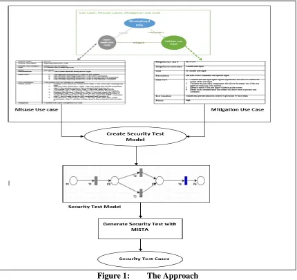
As shown in Figure 1, the approach consists of three steps: (1) conduct misuse case modeling, (2) create security test model, and (3) generate security test cases from the security test model by using The MISTA tool. In the following, we elaborate on each of them.
3.1 Misuse Case Modeling
Misuse case modeling is the first step in our approach. It describes security attacks against use cases as well as the security features needed to mitigate them.
3.1.1 Defining Use Cases
Use cases describe the functional requirements of the system under development. Use case modeling is a structured approach to addressing the interactions between a system and its actors. In this research, the following steps are used to define use cases:
Define use case actors, their desired system functions, and interactions between actors and system functions according to system documentation, interviews with the system stockholders, and user experiences.
Create a use case diagram which depicts the actors, use cases, and interactions. Create use case textual description.
Figure 2 provides a sample use case diagram that consists of “Create New Proposal Document”, “Submit a Proposal by PI”, “Save Proposal”, and “Notify Users” use cases. The arrows between the actor and the use cases represent the relationship between the use cases and the actor. An “include” relationship is signified by using an arrow that is labeled “include”. The extend relationship is represented by an arrow labeled “extend”.
Table 1 shows the template of use cases used in this thesis. Generally, the description of a use case consists of; use case ID, name, actor, goal, precondition, post-condition, extension points, alternative flow, exception flow, and recovery flow that describe the system requirement, goals and the interaction between the actor and system. The extension points field is used to represent the extend relation with other use cases and an underlined step in the main flow is used to indicate to the reader the “include” relationship of other use cases. Table 2 shows a sample use case description.
Table 1. Use Case Template.
Use case # Represents the use case number, that can be used for
tracing the use cases.
Use case name Represents the name of the use case.
Actor Represents the actors of the use cases, by listing all the
stakeholders that will use the use case. Goal Represents the target of the use case.
Preconditions Represents the conditions that the system should ensure to
be true before starting the use case
Main Flow
Represents a sequence of steps that describe how the use case goal can be achieved. Main flow represents the interactions between the actors and the system feature.
Post-Condition use case. Represents the states of the system after the execution of the
Extensions Points
In some cases, a use case may extend other use cases whose details described in other use case description.
Alternative flow Represents a set of alternative steps that can be performed
instead of one or more step in the main flow.
Exception flow
Represents a set of conditional steps that are a response to the exceptions in one or more step in the main flow that prevent the use case from achieving its goal.
Recovery flow
Table 2: Description of Use Case “Submit a Proposal by PI”
Use case # UC-3
Use case name Submit a proposal by principal investigator (PI).
Actor Principal Investigator (PI).
Goal To submit the proposal by PI.
Preconditions
1. The PI created the proposal and signed it. 2. The Co-PI(s) signed the proposal.
3. The proposal status not submitted.
Main Flow
1. The actor login to account.
2. The actor selects “My proposals” action.
3. The actor selects the proposal by selecting the edit proposal action.
4. The system opens the proposal in edit mode. 5. The actor signs the proposal.
6. The actor selects the submit action.
7. The system sends a notification to the department chair, PI, Co-PI(s) and Senior Personnel.
8. The system records the request in the user audit log.
Post-Condition 1.2. The proposal status changed to waiting for chair approval. The actor has read access to the proposal.
Extension Points 1. Step 7, extends Notify users use case.
Alternative flow
2.a The actor uses the research engine 2.a.1 The actor inserts the proposal information in the
search fields.
2.a.2 The system returns the search result. 2.a3 The actor selects the proposal. The use case continuous at The actor selects the submit action in MF
Exception flow
4.a CO-PI(s) not signed the proposal
4.a.1 The system shows an error message that CO-PIs are not signed on the proposal.
Recovery flow None.
3.1.2 Defining Misuse Cases
Define the misuse case actors, what potential security threats they represent, and the interaction between the actors (i.e., Adversaries) and the system functions in structured and systematic manner. This is done by applying all potential STRIDE threats (spoofing identity, tampering with data, repudiation, information disclosure, denial of service, and elevation of privilege) and security goals (Authentication, Authorization, Confidentiality, Integrity, Accountability, Availability, Non-repudiation) to each step in the main flow and alternative flow of use cases. Extend the use case diagram to include the misuse cases. Use case/misuse case
diagram depicts the misuse cases and threaten use cases. Create a textual description for each misuse case.
Figure 3 is a sample use case/misuse case diagram that consists of the use cases denoted by blue ovals, and the actor in the regular use case diagram (see Fig.2). The diagram also shows the threat in terms of misuse-actor and misuse case. The misuse actor and misuse case are colored with inverted colors like black or gray colors to distinguish them from the use cases and the use case actors. Additionally, “threaten” is the relationship between the use case and misuse case. Each use case may be threatened by several misuse cases and each misuse case may threaten many use cases.
Table 3 shows the template for misuse case textual description used in this thesis. Similar to the use case description, misuse case description has; misuse case ID, name, goals, actor, preconditions, post-conditions, and main flow fields that describe in detail what the adversary might try to do. The differences in misuse case description from the use case description are: misuse case category field is used to classify the misuse case category according to STRIDE classification, a threat point field that lists the use cases threatened by the misuse case, and mitigation filed representing the mitigation use case that can mitigate the misuse case. Table 4 shows an example of misuse case textual description. Table 3: Misuse Case Template
Misuse case # Represents the misuse case number. This field used
for tracing and organizing the misuse cases.
Misuse case name Represents the misuse case name.
Misuse case category Represents misuse case STRIDE classification
Goal Represents the goal of misuse case
Actor Represents the actors of the misuse cases, by listing
the possible adversaries.
Preconditions
Represents the conditions that should be true before performing the attack. For example, having username and password of a system user
Main Flow Represents a sequence steps that demonstrate the
scenario of the attack.
Post-conditions Represents the states of the system after performing
the misuse case.
Threat point Maps each misuse case to any use case that threaten
by
Mitigation Map the misuse case to any mitigation use case that
mitigated by.
Table 4: Description of “URL Redirect” Misuse Case
Misuse case # MUC-1
Misuse case name URL Redirect Attack.
Misuse case category Information disclosure, DoS and elevation of
privilege.
Actor Adversary
Preconditions 1. The actor has an account on the system or has other user
login information.
Main Flow
1. The actor login to the system. 2. The actor selects my proposal action.
3. The actor selects a proposal and opens it by select edit action.
4. The actor injects the malicious code in the signature field. 5. The actor selects one of the saves, submit, approve or
disapprove proposal actions.
Post-conditions 1. The system will redirect the user to the malicious site.
Threat point
1. Approve/Disapprove proposal by Dean, Main flow, step 3, The actor sign the proposal.
2. Approve/Disapprove proposal by IRM, Main flow, step 3, The actor sign the proposal.
Mitigation Cross-site Scripting (XSS) prevention.
3.1.3 Defining Mitigation Use Cases
Mitigation use cases represent the countermeasure requirements of the misuse cases. In order to define the proper mitigation use case for each misuse case identified, the following steps have been applied;
Define the mitigation use cases by applying STRIDE and the Open Web Application Security Project (OWASP) [18] to each misuse case. STRIDE and OWASP were used as they represent both the application threats and the proper countermeasures.
Extend use case/misuse case diagram to include the mitigation use cases. Create a mitigation use case textual description.
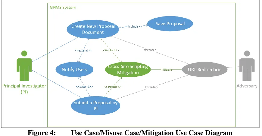
Cross-Site Scripting Mitigation) is colored green to distinguish it from the use cases, and misuse cases. An “include” relation is used to connect the use cases (i.e., Create New Proposal Document, Submit Proposal) with mitigation use case, and the “mitigate” relation used to connect the misuse case (i.e., URL Redirection Attack) and mitigation use case.
Figure 4: Use Case/Misuse Case/Mitigation Use Case Diagram
Table 5 provides the template of mitigation use cases used in this thesis. Similar to the use case and misuse case description, a mitigation use case description has: mitigation use case ID, name, goal, precondition, and post-condition fields. The differences between the mitigation use case description and use case description are: (1) the priority field that represents the importance of having the mitigation use case and, (2) the exclusion of an actor field. Table 6 shows a sample mitigation use case textual description.
Table 5: Mitigation Use Case Template Mitigation use case #
Represents the mitigation use case number. This field used for tracking and organizing the mitigation use cases.
Mitigation use case name
Goal Represents the goal that should be achieved from the mitigation use case.
Precondition Represents the conditions that initiate the mitigation
use case.
Main Flow security requirement implementation. Represents a sequence of steps that describe the
Post Condition Represent the system states after executing the
mitigation use case
Priority Represent the priority of mitigation use.
Table 6: Description of “Cross-Site Scripting” Mitigation Use Case
Mitigation use case # MITI-UC 1.
Mitigation use case name
Cross-site scripting (XSS) prevention.
Goal To prevent the XSS attack.
Precondition 1. The actor injects malicious script code.
2. The actor uploads malicious script code.
Main Flow
1. Validate user input by using whitelist technique. 2. Use Output Escaping technique to ensure any JavaScript
code is converted to safe display.
3. Use HTML escape JSON values and decode the JSON values and safely parse it.
Post Condition
1. The XSS attack malicious code will not be executed. 2. The application will render the web pages safely and
appropriately.
3. The application protects the user data.
Priority High.
3.2 Extract Security Test Model
A security test model is represented as a Predicate/Transition (PrT) net in the MISTA tool. A PrT net is a 7-tuple <P, T, R, L, Ʃ, ϭ, M0>, where,
1. P is a set of places (circles) that represent a state or condition.
2. T is a set of transitions (rectangles) that represent functions or events.
3. R is a set of normal arcs, representing a relationship between a place and a transition.
5. Ʃ is a set of constants and relations (e.g. arithmetic relation). 6. Ϭ is a guard function on T.
7. M0 is initial marking, where, M0 (P) is the set of tokens in predicate P, and each token is a tuple in Ʃ.
3.2.1 Transforming Misuse Case Textual Description into PrT Net
We extract PrT net based on the main flow of a misuse case which depicts a sequence of steps to be followed by the adversary to compromise the system. Misuse case main flow description includes different types of steps that represent an attack on the system. For example, a Repetitive step represents a reiteration of an attack, for instance, one in which new user accounts are created automatically. In this research, four types of steps have been defined; Simple step, Repetitive step, Conditional step, and Concurrent step. The representation of those steps in PrT net is discussed in the following sections.
3.2.1.1 Mapping a Simple Step into PrT Constructs
Simple Step represents executing a simple operation in the system environment by the actor. One example would be; select login action or submit proposal action. This step can be represented in PrT net as follow:
1. Define one transition “t” that represents the Simple Step. 2. Define input place P-IN and output place P-OUT.
3. Use input arc R-IN to connect the input place P-IN with transition “t” and output arc R-OUT to connect the transition “t” with output place.
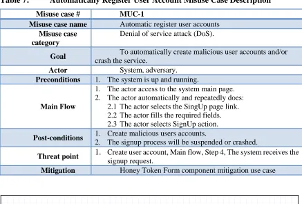
In Table 7, the first step in the main flow is an example of a Simple Step. Figure 5 shows the representation of a Simple step by the first step in Table 7.
Table 7: Automatically Register User Account Misuse Case Description
Misuse case # MUC-1
Misuse case name Automatic register user accounts
Misuse case category
Denial of service attack (DoS).
Goal To automatically create malicious user accounts and/or
crash the service.
Actor System, adversary.
Preconditions 1. The system is up and running.
Main Flow
1. The actor access to the system main page. 2. The actor automatically and repeatedly does:
2.1 The actor selects the SingUp page link. 2.2 The actor fills the required fields. 2.3 The actor selects SignUp action.
Post-conditions 1. Create malicious users accounts.
2. The signup process will be suspended or crashed.
Threat point 1. Create user account, Main flow, Step 4, The system receives the
signup request.
Mitigation Honey Token Form component mitigation use case
Figure 5: Simple Step Mapping Example 3.2.1.2 Mapping a Repetitive Step into PrT Constructs
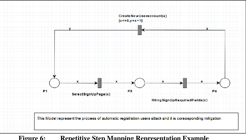
a repeat, iterate, loop, and other keywords demonstrate that the step is repetitive. In misuse case or use case textual descriptions, a Repetitive step has sub-steps which represent the repetitive blocks as shown in Table 7 above. Step 2 represents an example of a repetitive step and the sub-steps 2.1, 2.2, and 2.3 are the repetitive block. Repetitive steps can be mapped to PrT constructs as follow:
1. Define a transition “t(i)” for each repeatable block. For example, in step 2 we have 3 sub-steps (repeatable blocks), so we create 3 transition “t(i)” (e.g. i = 1,2, 3…., n).
2. Define input place P-IN for each transition “t(i)”. For step 2 in the table, we create 3 P-IN places.
3. Connect each input place P-IN with transition “t(i)” by using input arc.
4. Connect transition “t(i)” with P-IN(i+1) by using output arc. For example, connect the transition of first repeated block with input place of the second transition. 5. Connect the last transition “t(n)” with first input place “P-IN (i=1)” by using output
arc. For example, connect the transition of sub-step 3 with input place of the first transition.
6. Define the guard condition that control the loop in the last transition “t(n)”. The guard condition can be explicitly or implicitly defined in the repetitive step. The guard condition will have two variables, the first variable (e.g. X) represent the number of iterations and other variable (e.g. Y) used to update the loop control value.
other Arc labels will hold the first variables. Figure 6 shows an example of mapping step 2 into PrT construct, each transition corresponds to each sub-step, the guard condition has the variables X and Y, and arc labels defined to hold the guard condition variables between transitions.
Figure 6: Repetitive Step Mapping Representation Example 3.2.1.3 Mapping a Concurrent Step into PrT Constructs
A Concurrent or Parallel step represents a parallel/concurrent action executed by an actor on the system environment. Keywords like parallel, concurrent, and other keywords indicate that it is a concurrent step. Similar to the repeatable step, the concurrent step has sub-steps or blocks that represent the parallel blocks. Concurrent step is mapped to PrT constructs as follows:
1. Define a transition “t(i)” for each block.
3. Use output arc “R-OUT” to connect each transition with corresponding transition t(i).
4. Define Input Place “P-IN”, that will be representing the input place for all of the transitions.
5. Use input arc “R-IN” to connect the “P-IN” with all transitions “t(i)”.
6. Use arc label for “R-IN” to define the input parameters and arc label for “R-OUT” to define the output parameter if that parameter exists.
Figure 7 shows an example of mapping a Concurrent into PrT construct. The “INPUT PLACE” represents the input place for the concurrent net and the “Input-T1, Input-T2 and Input-T3” are the input parameter for T1, T2, and T3 respectively and “Output-T1, Output-T2, and Output-T3” represent the output parameter for T1, T2, and T3, where, “T1-Output-Place, T2-Output-Place, and T3-Output-Place” represent the output place for the T1, T2, and T3 respectively.
3.2.1.4 Mapping a Conditional Step into PrT Constructs
A Conditional step is a simple step with a guard condition. Conditional step contains two parts, IF and ELSE parts. The guard condition of the conditional step can be extracted from the IF part. Conditional step can be mapped into PrT construct as follows:
1. Define transition “t” for IF part and other transition “t” for the EISE part. 2. Define output place for each transition in previous step P-OUT.
3. Define a single input place P-IN for the conditional step (i.e. for the IF part and ELSE part).
4. Use input arc R-IN to connect the P-IN with all transitions.
5. Use output arc R-OUT to connect each transition with corresponding output place P-OUT.
6. Define guard condition for each transition.
7. Use input arc label to define the input parameter for each transition and output arc label to define the output parameters.
Figure 8: Conditional Statement Mapping Example. 3.2.1.5 Mapping Misuse Case Main Flow into PrT Constructs
The misuse case main flow may have a combination of more than one step of different types, such as simple step and/or repeatable step, representing the attack scenarios. In order to extract the PrT constructs from the main flow that represents the misuse case security test model, the following steps have been followed:
1. Misuse case main flow consists of “I” steps (e.g. I = 1, 2, 3... n). Starting from the first step of the main flow of the misuse case, define the step type (e.g. Simple step).
2. Based on the step type, use the steps that have been specified and explained in the previous sections to model the step in PrT constructs.
3. Repeat the previous two steps through to the final step of the main flow.
5. Verify the precondition of each step (i). The precondition of the transition represents the input places and associated arc labels, however, some of the transition “t (i)” has two input places. The first input place comes from step modeling itself, based on its type. The other input place will come from step 4; if the two input places are identical, the input place and directed arc that was created by step modeling based on its type should be removed, keeping the input place which was created from step 4. Figure 9 shows an example of the extracted security test model from Automatically Register User misuse case (see Table 7).
Figure 9: Misuse Case Mapping Representation Example. 3.2.2 Transforming Mitigation Use Case into PrT Constructs.
against attacks. For example, in an FTP server after executing a command, the FTP server responds with an integer value, the integer value returned represents a validation point (e.g. 0 if successful, any other value if failed). In GPMS application, after performing a redirect to another website attack, the validation point will be a GPMS proposal document and not another website. To represent the mitigation use cases in PrT constructs, these steps have been applied:
1. Define a transition “t” for the validation point. 2. Define a P_OUT place for the transition “t”.
3. Use output arc to connect the transition “t” with P_OUT place. 3.2.3 Combine Misuse Case and Mitigation Use Case into PrT Constructs
A security test model consists of misuse cases PrT constructs and mitigation use cases PrT constructs. The security test model represents the attacks and the mitigation mechanism. To combine the misuse cases PrT with mitigation use case PrT:
1. Use input arc “R_IN” to connect the final place of the misuse case PrT that represents the P_OUT place of the last transition in the main flow of the misuse case with mitigation transition “t”.
Figure 10 : Security Test Model Example. 3.3 Combine Security Test Models.
there was a proposal to combine the security test models into one security test model. There are two ways to combine the security test models that have been created. The first method is based on STRIDE and the second is based on the Use Case. The main objectives of combining the resulted security test models were to improve the quality of generated security test cases by reducing the possibility of generating duplicated security test cases and reduce the time and effort needed for the modeling process.
3.3.1 Combine Security Test Models Based on STRIDE
The misuse case textual description has a misuse case category field, representing the misuse case category based on STRIDE methodology. This field has been used to combine the misuse cases that have the same STRIDE category to in one security test model. To combine the misuse cases based on STRIDE, the following steps have been applied:
1. From misuse case category, collect all the misuse cases that have the same STRIDE classification.
2. In one security test model, map each misuse case into PrT construct based on the mapping or modeling techniques discussed in the previous sections. In this step, each misuse case will be modeled to cover all the threaten use cases listed in the threat point of misuse case textual description.
3. Model each mitigation use case for each misuse case based on the mitigation modeling techniques discussed in the previous section.
5. Use arc label enumeration to specify each misuse case with corresponding mitigation use case.
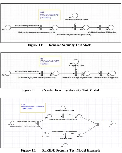
6. Define the initial marking M0 for the security test model. Figure 13 shows an example of combining misuse cases based on STRIDE.
Figure 11: Rename Security Test Model.
Figure 12: Create Directory Security Test Model.
3.3.2 Combine Security Test Models Based on Use Case.
Combining the generated security test models based on Use Case represents the second technique of improving the quality of the generated security test models. This technique targets all possible specific functional requirement attacks on the system, represented by misuse cases. To combine all misuse cases that belong to a specific use case, the following steps have been followed:
1. From the threat point of misuse cases textual description, collect all the misuse cases that belong to the targeted use case.
2. In one security test model, model each misuse case based on the mapping or modeling techniques discussed in the previous sections.
3. Combine all the transitions that perform the same functionality in one transition. 4. Model each mitigation use case for each misuse case based on the mitigation
modeling techniques discussed in the previous section.
5. Use arc label enumeration to specify each misuse case with corresponding mitigation use case to map each misuse case with related mitigation use cases in the generated security test case.
6. Define the initial marking M0 of the security test model.
3.4 Generate Security Test Cases
The MISTA tool is used to generate security test cases from the security test model. The MISTA tool is a Model-Based Integration and System Test Automation. It generates executable test code in different languages (e.g. Java, C, C++, C#, VB, HTML) based on a given Model Implementation Description (MID). MID consist of a test model, Model Implementation Mapping (MIM), and user-provided Helper Code (HC). To create test cases by using MISTA we follow the following steps.
1. Build Test Model. MISTA uses function nets high-level Petri nets as a primary notation for a test model. We use the security test model that has been created in the previous step to be the test model.
2. Create MIM Specification. MIM maps the elements of the test model into implementation constructors for test code generation. MIM include different options elements such as hidden event/conditions, object, methods, options, accessors, and mutators. However, we used object option that maps constants in all token to the objects, the constants we have in the test model like injecting code. We also used methods that map the events/transitions in the test model to a block of code.
for GPMS system by using reachability tree coverage. Figure 15 shows an example of generated security test case for FileZilla server in C and Figure 16 shows an example of security test case in Java for GPMS system.
Figure 15: A Sample FileZilla Server Security Test Case.
CHAPTER FOUR CASE STUDY I: FILEZILLA FTP SERVER
In order to validate the applicability of the proposed approach, two case studies have been conducted: FileZilla FTP server, and GPMS. The two applications have different business logic, user and system requirements, and programming languages.
File Transfer Protocol (FTP) is a standard protocol, used widely with remote computer systems and transferring files between systems. FileZilla FTP server is a popular FTP server implementation which, as of April 2016, is the seventh most downloadable program on Source Forge [21]. FileZilla server 0.9.53 has 90,653 line of C++ code and 123 classes used in this case study.
4.1 Misuse Case Modeling 4.1.1 Defining FileZilla FTP Server Use Cases
Figure 17: FileZilla Server Use Case Diagram.
Table 8: FileZilla FTP Server Delete Files Use Case Textual Description.
Use case # UC2
Use case name
Delete files and/or Directories.
Actors User, System.
Goal To delete a file or/and directories from the client machine to
FTP server.
Preconditions 1. The system is up and running.
2. The actor logged into the system.
Main Flow
1. The actor provides the “DELE” command with remote
destination folder/directory path and its name by using command line tool.
5. The system provides the actor a summary of file/directory deleting process.
6. The system records the request in the log file.
Post-conditions
1. The file or directory is deleted successfully.
Extension Point
NONE
Alternative Flow
1a. The actor uses GUI client application.
1.a.1. The actor selects the file/directory that wishing to delete in the remote destination folder.
1.a.2. The actor deletes the file or directory from the available actions provided from file or directory properties. The use case continuous at System validates source file path in the MF.
Exception Flow
3.a. The file name does not exist.
3.a.2 The system throw error message telling the client that the file does not exist.
Recovery Flow
4a. The destination path does not exist or invalid file/folder name.
4. a.1 The system notifies the actor that the destination does not exist. The use case continuous at the actor provides “DELE” command with existing destination folder path or with valid file/folder name in the MF.
4.1.2 Defining FileZilla FTP Server Misuse Cases
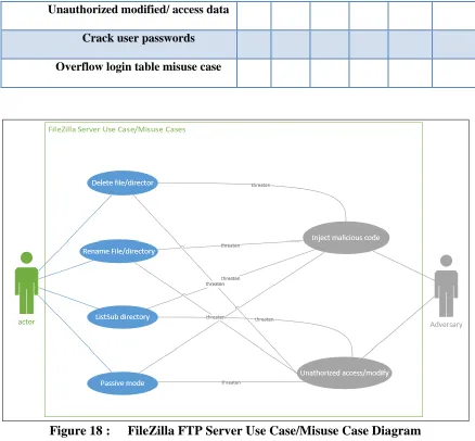
Misuse cases are defined in examining all of the security goals and each STRIDE type of every step in the main flow and alternative flow for each use case. Table 9 shows the misuse cases created corresponding to STRIDE. After defining misuse cases, a use case/misuse case diagram has been created and is shown in Figures 18. After that, a textual description for each misuse case has been created. Table 10 is an example of the misuse case textual description.
Table 9: Misuse Cases Corresponding to STRIDE
Misuse case name S T R I D E
Unauthorized modified/ access data * * * *
Crack user passwords *
Overflow login table misuse case * *
Figure 18 : FileZilla FTP Server Use Case/Misuse Case Diagram Table 10: Inject Malicious Code Misuse Case Description
Misuse case# MUC 2
Misuse case name Injecting malicious code Attack
Misuse case category Denial of service attack
Goal To disturb the system services
Actor Adversary
Preconditions 1. The attacker has an account on the system.
Main Flow
1. The attacker anonymously login to the system.
2. The attacker issues MKD command with injecting malicious code.
Threat point
1. Rename File, Main flow, Step 1, the user sends the RNTO command, step 2, the system receives the command and process it.
Mitigation Validate user input mitigation use case
4.1.3 Defining FileZilla FTP Server Mitigation Use Cases
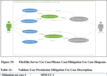
For each misuse case, the proper mitigation use cases have been identified by using STRIDE and other security references such as OWASP. A textual description has been created for each. Table 11 is an example of mitigation use case textual description. Figure 19 shows an example of FileZilla FTP Server use cases/misuse cases/mitigation use cases diagram.
Figure 19: FileZilla Server Use Case/Misuse Case/Mitigation Use Case Diagram. Table 11: Validate User Permission Mitigation Use Case Description.
Mitigation use case # MITI-UC 2
Mitigation use case name
Validate user permission
Goal To validate the user permission before access and/or
Precondition The actor login to the system as an anonymous or legitimate user.
Main Flow
1. Retrieve the actor permission.
2. Read the actor permission for the requesting command. 3. Return the right actor permission for the requesting command. 4. Based on the returned result the system will throw error
Post Condition Read and validate the right the permission for the actor.
Priority High
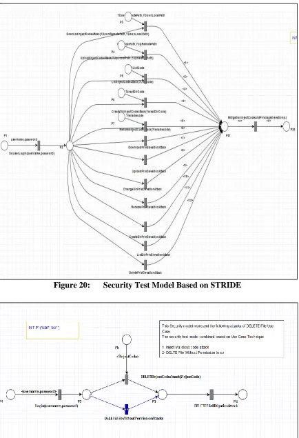
4.2 Create Security Test Model
Figure 21: Security Test Model Based on Use Case. 4.3 Generate Security Test Cases
FileZilla FTP server security test cases have been generated based on the extracted security test models by using MISTA tool. MISTA tool generates test cases based on the given MID. A MID has been created which consists of the test model, MIM, and HC. After implementing all of these, MISTA generates test cases. Figure 16 gives an example of these generated test cases.
Figure 22: FileZilla FTP Server Security Test Case. 4.4 Evaluation of Security Test Cases.
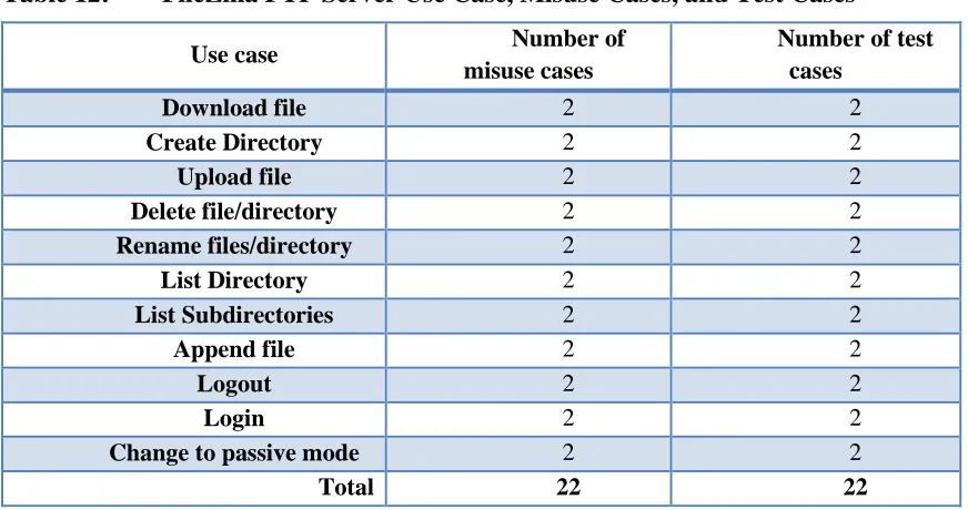
After applying the presented approach, 11 use cases have been identified, covering the majority of the FileZilla FTP server functionalities. Table 12 shows; the use cases, the number of misuse cases, and the number of security test cases have been generated for each use case.
system to test whether the test cases can find the injected faults or not. A mutant is a version of software source code with injected faults. 38 security mutants were created using common vulnerabilities in C++ and security problems with FTP. This process is shown in Table 13.
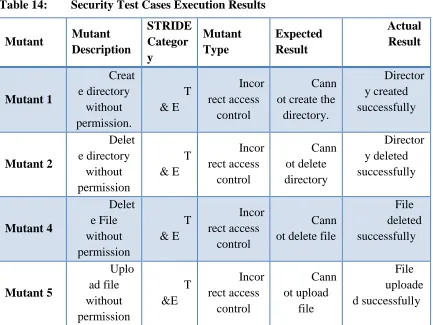
The vulnerability is revealed; a mutant is said to be killed if one of the security test cases successfully attack. Security test cases were executed against the created mutants, killing 33 out of 38 mutants. The five remaining mutants have logical errors in the administration functions provided by FileZilla server that could lead to different attacks such as DoS. The behavior of these security vulnerabilities is not included in the misuse case modeling. Table 14 shows the results of performing the security test cases against the mutants. These results show the mutant name, the mutant description, the STRIDE category, the expected result, and the actual results of executing the security test cases.
Table 12: FileZilla FTP Server Use Case, Misuse Cases, and Test Cases
Use case Number of
misuse cases
Number of test cases
Download file 2 2
Create Directory 2 2
Upload file 2 2
Delete file/directory 2 2
Rename files/directory 2 2
List Directory 2 2
List Subdirectories 2 2
Append file 2 2
Logout 2 2
Login 2 2
Change to passive mode 2 2
Table 13: FileZilla Server Security Mutants
Table 14: Security Test Cases Execution Results
Mutant Mutant Description STRIDE Categor y Mutant Type Expected Result Actual Result Mutant 1 Creat e directory without permission. T & E Incor rect access control Cann ot create the directory. Director y created successfully Mutant 2 Delet e directory without permission T & E Incor rect access control Cann ot delete directory Director y deleted successfully Mutant 4 Delet e File without permission T & E Incor rect access control Cann ot delete file
File deleted successfully Mutant 5 Uplo ad file without permission T &E Incor rect access control Cann ot upload file File uploade d successfully
Vulnerability type Number of
mutants
Number of mutants killed
Buffer overflow 3 3
Logic errors 8 8
Password management errors
2 2
Memory leak 2 2
Format String 2 2
Integer overflow 1 1
Incorrect access control 14 11
Business logic flaws 6 4
Mutant 6 Rena me File/Dir without permission T &E Incor rect access control Cann ot rename file/Dir File/Dir renamed successfully Mutant 7 Bann ed IP can still log in
E Logi
c errors
IP will be banned for a
certain amount of time User can login Mutant 8 Dow nload file without permission I & E Incor rect access control Cann ot download file File downloa ded successfully Mutant 9 No password needed for login S & E Logi c errors Cann ot login User Login successfully Mutant 10 Show user passwords in clear text S & R & I
Pass word management errors Pass word should willed be starred (*) Passwor d printed in clear text on the
server interface Mutant 11 No logs kept even if logging enabled
R Busi
ness Logic errors User login should be Logged No logs kept Mutant 12 Filter ed IP can still log in
Mutant 14
A user with no
list permissions
logging on causes FTP service to quit when it
gets to listing the directory with the LIST command. D Incor rect access control Serv er stay running and does not list directories
Server crashed
Mutant 15
If the user tries to delete directory all files inside the subdirectories are deleted but none of the directories are deleted. T &E Incor rect access control Cann ot delete files and directory Files and directories are deleted successf ully Mutant 16
A user with no permissions can
delete directories that
are empty and directories that are full of files
and other directories. T &E Incor rect access control Cann ot delete files and directory Files and directories are deleted successf ully Mutant 17 Log out the login
user
D Logi
c errors User can login and perform commands User login to the
server but immediately disconnected from the server
successf ully Mutant 19 User can subdirectorie s without permissions I & E Incor rect access control User cannot subdirectori es User Success fully subdirec tories Mutant 20
a user with Force SSL checked can
still log on without using SSL authentication E Incor rect access control
Cannot log in without SSL error message User Successfully login Mutant 21
Spoofs the first user created on server with any credentials except a blank
username
S Logi
c errors Cannot login error message User Successfully login Mutant 22 Spoofs first user created on server with any credentials
S Logi
c errors Cannot login error message User Successfully login Mutant 23
No user or group settings are saved. D Busi ness Logic errors User successfully logs in
User Cannot login, error message
Mutant 26
Denial of Service for the
QUIT command. Users can’t log off using QUIT
command.
D Business Logic
errors.
User is disconnected
Successful QUIT message but user is
still connected to the server
Mutant 27
Denial of Service for the
PASV command.
D Logic errors.
User successfully enters passive mode. Cannot enter passive mode, error message.
Mutant 29
QUIT command is
issued a memory leak is
caused.
D Mem
ory leak
The memory of the process
will go down when QUIT command is
issued.
The allocated memory of the process will stay
the same when QUIT command is
Mutant 30
Denial of Service for the
CWD command.
D Logic errors.
User successfully
changes directory
Cannot change directory, and the server disconnect the connection Mutant 31 Format String Error that causes the server to crash when the LIST command.
D Format String
The user gets a listing of files
and directories.
Server Crashed
Mutant 33
No file log will be deleted
using the configuration settings to set how big the collective files can get or to get
rid of old log files by date.
D Logic errors. Some logs were deleted.
No logs were deleted
Mutant 34
Memory leak is created when
the PASV.
D Memory leak
The memory of the process
will go down when a new
PASV command is
issued.
Memory of the process will goes up when a PASV command is issued
Mutant 35
The user can issue many consecutive commands causing the server to be slow to respond
to other commands.
D Business Logic
errors.
Server builds up a wait time
for your next login.
Server gets bogged down from multiple login or
commands.
Mutant 36
Integer overflow causes an error
that won’t allow the user
to change to passive mode.
D Integer
overflow User successfully enters passive mode. Cannot enter passive mode error