Volume 2, Special Issue 1 MEPCON 2015
68
Available online at www.ijiere.com
International Journal of Innovative and Emerging
Research in Engineering
e-ISSN: 2394 - 3343 p-ISSN: 2394 - 5494
Intelligent Alternator Controller: Prototype and Testing
V. B. Bhamare1
a, V. S. Narwane2
aand K. R. Pagar3
b a K J Somaiya College of Engineering, Mumbai, Indiab Greaves Cotton Technology Centre, Aurangabad, India
ABSTRACT:
In the world development is going on, which is continuously increasing pollution in the environment and automotive sector's contribution is in the large scale. To reduce pollution from vehicles, government sets strict norms for the emission controls of new vehicles production. Alternator is one of the vehicle components, which is contributing in vehicles emission and performance indirectly.
In conventional engine control system it is not possible to optimize the efficiency of the alternator in terms of emission and fuel consumption, due to constant voltage output and continuous loading condition. By controlling the alternators loading, it is possible to reduce fuel consumption and increase emission margin. This paper covers the approach to make alternator intelligent by implementing controller which control alternators loading and unloading in MIDC (Modified Indian Driving Cycle) on chassis dynamometer and on road conditions.
Keywords: Intelligent Alternator, INCA, MDA, MIDC
I. INTRODUCTION
In vehicle electrical power is required, which is fulfill by 12V battery but its continuous utilization make it discharge. So to charge battery we need an alternator. For more luxury and more functionality we are introducing number of devices in vehicle, so that the electrical power requirements in vehicles have been rising rapidly for many years and are expected to continue to rise. The continuous increase in power requirements is pushing the limits of conventional automotive power generation and control technology and is motivating the development of both higher-power and higher-voltage electrical systems and components.
Electrical System Used in Conventional Vehicle.
Alternator is a synchronous AC electric generator with DC diode rectification and pulse width modulation voltage control. In conventional vehicle alternator is in continuous loading condition. Conventional alternator is having efficiency of 35-45% (Bosch ~ 40-35-45% and TVS Lucas ~ 35-40%). A typical LCV (Light Commercial Vehicle) electrical power requirement is ~400-500 watts and to fulfill this requirement alternator consumes ~1-1.5 hp from engine. This causes more fuel consumption and more emission.
Fig. 1 Alternator working scheme
69
Fig. 2 MIDC driving cycle
MIDC is a typical driving cycle shown in figure 2, which design according to Indian road conditions and driving pattern. Vehicle emission is tested in ARAI, Pune running vehicle on MIDC driving cycle. Following are details of MIDC driving cycle,
Total test time : - 1180 seconds Total distance : - 10.647 km Maximum speed : - 90 kmph Max Acceleration : - 0.833 m/s2 Max Deceleration : - 1.389 m/s2
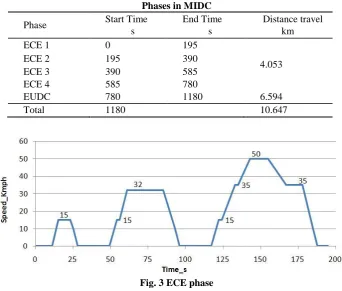
In MIDC driving cycle is consists of two phases Elementary Cycle of Emission (ECE) and Extra Urban Driving Cycle (EUDC). Following table explains the phases, duration of the driving cycle and travel distance [3].
TABLE I Phases in MIDC
Phase Start Time
s
End Time s
Distance travel km
ECE 1 0 195
4.053
ECE 2 195 390
ECE 3 390 585
ECE 4 585 780
EUDC 780 1180 6.594
Total 1180 10.647
Fig. 3 ECE phase
Volume 2, Special Issue 1 MEPCON 2015
70
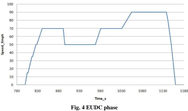
Fig. 4 EUDC phase
Fig. 4 shows EUDC phase. The EUDC segment has been added after the fourth ECE cycle to account for more aggressive, high speed driving modes. EUDC represents the highway road condition, we can simulate vehicle on highway road condition in chassis dynamometer.
In any driving cycle vehicle follow four different modes of operation. The stationary mode where fuel is burnt to keep engine running, the acceleration mode where fuel is burnt to accelerate or move the vehicle, the cruising mode where small amount of fuel is burnt to keep vehicle running, and deceleration mode where fuelling is stopped [1], [2].
Conventional alternator reacts same way in all vehicles operating mode. It continuously generates 14.4V at 250C ambient temperature, irrespective of driving mode or fuel burning or not. If we properly manage the vehicle fueling and loading of accessories like alternator then fuel efficiency of vehicle can be improved. It is very helpful to unload alternator in engine acceleration and idle mode. Load the alternator in deceleration, cruising mode also in braking conditions.
III.INTELLIGENTALTERNATORSYSTEM
Intelligent alternator systems block diagram is shown in fig. 5
Fig. 5 (a) Block diagram of intelligent alternator system
Fig. 5 (b) Block diagram of Intelligence
71
Cooling system Water cooled
Rated Power 12HP @ 3000 rpm
Max. Torque 35 Nm @ 16000 rpm
EGR Proportional
Auxiliary systems EGR cooler, Oil mist separator
Vehicle dynamic behavior is studied through data logging device and INCA data acquisition software. Recorded data is analyzed in MDA [7], [8].
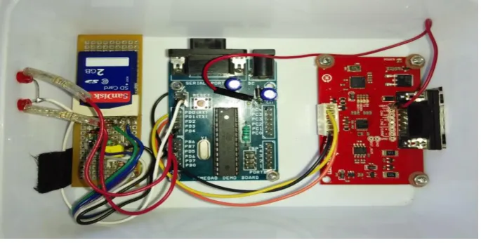
For data logging from vehicle Arduino electronics hardware is prepared which is connected to OBD communication port and this device logged real time data which is stored in memory card. This is very useful device for monitoring the vehicle dynamic on road conditions. The fig. 6 shows the real time data logging device.
Fig. 6 Real time Data logging device
Table III shows the sample of real time data logged in memory card.
TABLE III. Real Time data logged
Volume 2, Special Issue 1 MEPCON 2015
72
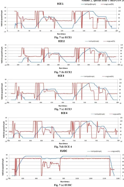
Fig. 7 (a) ECE1
Fig. 7 (b) ECE2
Fig. 7 (c) ECE3
Fig. 7(d) ECE 4
73
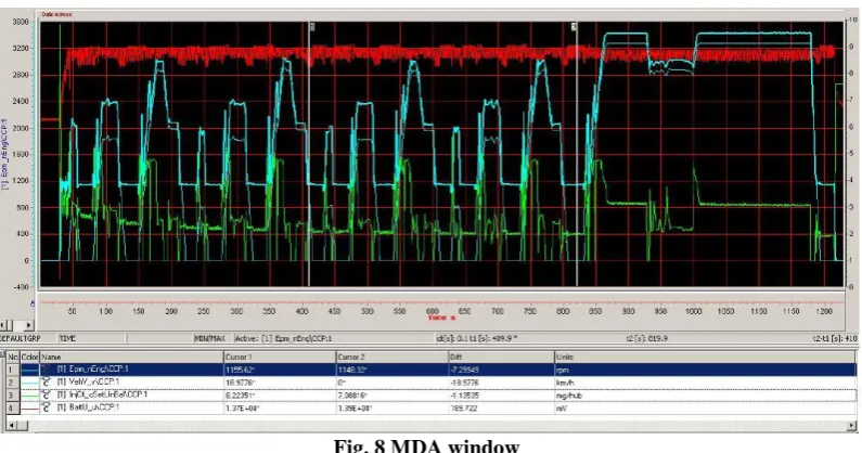
Fig. 8 MDA window
INCA measures data during MIDC and in MDA same data is analyzed. Individual variables are analyzed and alternator loading and unloading points are determined.
IV.CONCLUSION
Reference [1], [2] shows that fuel efficiency can be improved by ~4 - 7% and ~3 - 3.5 g/km CO2 benefit is possible by using smart alternator.
Vehicle emission test is successfully conducted on chassis dynamometer and vehicle behavior on on-road, both results are analyzed and energy recuperation points are determined for alternator loading and unloading. Programming of controller is under process, after completion of program. Vehicle trials will be conducted, so fuel efficiency and emission effect due to controller will be analyzed.
REFERENCES
[1] Venkatnarayanan Lakshminarasimha and Gopal Athani TATA Motors Ltd. “An Intelligent alternator control mechanism for energy recuperation and fuel efficiency improvement” by Published 04/08/2013
[2] Montalto I., Tavella lng D., Casavola PhD A., and De Cristofaro F. “Intelligent Alternator Employment To Reduce Co2 Emission and to Improve Engine Performance, “SAE Int. J. Alt. Power.2012.
[3] Indian Emission Regulations booklet by ARAI (Automotive Research Association of India )
[4] Heim, A. and Streibl, T., “The Intelligent Battery Sensor: Key Component for a Scaleable Motor-Vehicle-Independent Energy Management System,” 2006.
[5] Ludovic Doffe, Mostafa Kadiri Valeo Engine and Electrical Systems France, “Alternator Contribution to CO2 Emission Reduction Policies,” XIX International Conference on Electrical Machines – ICEM 2010, Rome
[6] Mike Bradfield “Improving Alternator efficiency Measurably reduces fuel costs”, Delco Remy Inc. USA [7] INCA handbook or manual
[8] www.etas.com
ABBREVATIONS
MIDC - Modified Indian Driving Cycle
INCA - INtegrated Calibration and Acquisition MDA - Measured Data Analyzer
![Fig. 1 Alternator working scheme The fig.1 shows schematics of the conventional electrical system used in vehicle [2]](https://thumb-us.123doks.com/thumbv2/123dok_us/8874214.1815878/1.595.168.433.550.716/alternator-working-scheme-shows-schematics-conventional-electrical-vehicle.webp)