© Strežniški vestnik 47C200158,435-440 ISSN 0 0 3 8 -2 4 8 0
UDK 5 3 8 .2
Izvirni znanstveni članek C1.015
©Journal of Mechanical Engineering 47C200158,435-440 ISSN 0 0 3 9 -2 4 8 0
UDC 5 3 8 .2 Original scientific paper [1 .015
ANALYTICAL REPRESENTATION OF THE INTERNAL SHAPE FACTOR
OF SHEATHED ELECTRICAL HEATING ELEMENTS
Sylvain LA LO T M.E.T.I.E.R.
Ecole d ’lngonieurs du Pas-de-Calais C am pus de la M alassise
B.P. 39
62967 Longuenesse Cedex France
Phone: +33 321 388 510 Fax: +33 321 388 505 Email: [email protected]
A B S T R A C T
This paper focuses on the study o f the internal shape factor of sheathed electrical heating elements. First, the studied geometries are presented and three dimensionless parameters are introduced. The analysis o f finite elements simulations leads to the proposition of an analytical expression of the dimensionless internal shape factor. Then a non uniformity factor is proposed and it is shown that this non uniformity is in all cases inferior to 6%, and in most cases inferior to l%. Then the proposed relation is applied to two examples, one determining the maximum heat flux for a given temperature, the second one determining the maximum temperature of the heating wire for a given heat flux.
INTRODUCTIO N
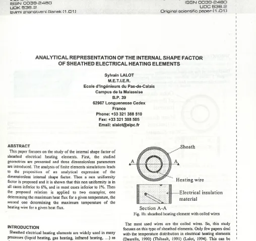
Sheathed electrical heating elements are widely used in many processes (liquid heating, gas heating, infrared heating, ...) as they are robust in a large temperature range. When the final user is not directly concerned by the internal temperature distribution, he is looking for a long life o f the heating element. This can be achieved by the manufacturer o f the element by carefully choosing the diameter o f the heating wire. This becomes important when the service temperature of the sheathed element becomes high (about 1,000 °C). The two main techniques that are used to manufacture sheathed electrical heating elements are presented in figure 1.
S e c tio n A -A
Fig. la: sheathed heating element with straight wires
H e a t i n g w ire
--- E l e c t r i c a l in s u la tio n
m a te r ia l
S e c t io n A -A
Fig. lb: sheathed heating element with coiled wires
The most used wires are the coiled wires. So, this study focuses on this type of sheathed elements. Only few papers deal with the temperature distribution in electrical heating elements (Daurelle, 1990) (Thibault, 1991) (Lalot, 1994). This can be due to the fact that this distribution strongly depends on the value of the thermal conductivity of the electrical insulation material. This value depends on the final value of the density of the material, and so depends on the way this material is compacted. It is possible to measure the thermal conductivity by comparing experimental data (e.g. the temperature difference between the axis o f the element and its surface for a known heat flux) and computed results. This has been done for few different types o f elements and at different locations (straight parts and bends), but the results are confidential. To avoid such confidentiality problems, instead of giving the internal thermal resistance, a dimensionless internal shape factor will be computed. This dimensionless shape factor is defined as the ratio of the actual shape factor to the shape factor of a heating element that would consist o f a continuous cylindrical heating part.
In a previous work (Lalot, 1994), it has been shown that the coiled wire may be approximated by a torus. This means that the 3D effect is negligible, and that axi-symmetric numerical simulations can accurately represent the actual phenomenon.
I
I
I5EB51
T H E O R E T IC A L D E V E L O P M E N T
Description of the studied geometries
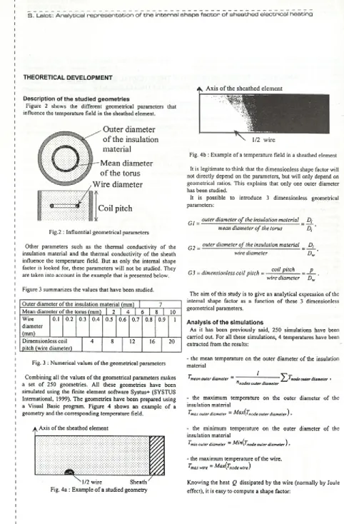
Figure 2 shows the different geometrical parameters that influence the temperature field in the sheathed element.
Outer diameter
o f the insulation
material
Mean diameter
o f the torus
Wire diameter
*
e : j 4
,
i
Coil pitch
Fig.2 : Influential geometrical parameters
Other parameters such as the thermal conductivity o f the insulation material and the thermal conductivity o f the sheath influence the temperature field. But as only the internal shape factor is looked for, these parameters will not be studied. They are taken into account in the example that is presented below.
Figure 3 summarizes the values that have been studied.
Outer diameter of the insulation material (mm)
Mean diameter o f the torus (mm) [ 2 | 4 | 6 1 8 10
Fig. 3 : Numerical values o f the geometrical parameters
Combining all the values of the geometrical parameters makes a set o f 250 geometries. All these geometries have been simulated using the finite element software Systus+ (SYSTUS International, 1999). The geometries have been prepared using a Visual Basic program. Figure 4 shows an example o f a geometry and the corresponding temperature field.
A , Axis o f the sheathed elem ent
Wire diameter (mm)
0.1 0.2 0.3 0.4 0.5 0.6 0.7 0.8 0.9 1
Dimensionless coil pitch (wire diameter)
4 8 12 16 20
1/2 w ire
Fig. 4b : Example o f a temperature field in a sheathed element
It is legitimate to think that the dimensionless shape factor will not directly depend on the parameters, but will only depend on geometrical ratios. This explains that only one outer diameter has been studied.
It is possible to introduce 3 dimensionless geometrical parameters:
^ _ outer diameter o f the insulation material _ £>,•
mean diameter o f the torus D,
_ outer diameter o f the insulation material _ Dj
wire diameter ’
G3 = dimensionless coil pitch = coil pitch _ p wire diameter
The aim of this study is to give an analytical expression of the internal shape factor as a function o f these 3 dimensionless geometrical parameters.
A n a ly sis of the sim ulations
As it has been previously said, 250 simulations have been carried out. For all these simulations, 4 temperatures have been extracted from the results:
- the mean temperature on the outer diameter of the insulation material
I J mean outer diameter ~ '
n nodes outer diameter node outer diameter >
- the maximum temperature on the outer diameter o f the insulation material
^'max outer diameter ~ M a x ij'notj e outer diameter ) »
- the minimum temperature on the outer diameter o f the insulation material
Tmin outer diameter ~~ ^ ^ n (Tnode outer diameter) »
- the maximum temperature o f the wire.
I'm ax wire ~ M a x (T node wire)
S =
max wire ~ ^mean outer diameter
Y
(i)
The mean temperature on the outer diameter has been chosen because it is the one that is easy to calculate during service. Usually, the convection coefficient between the sheathed element and the fluid to be heated is known. Knowing the temperature of the fluid and the amount o f heat per unit surface to be transferred, it is easy to calculate the mean surface temperature of the element. Knowing the thickness o f the sheath and its thermal conductivity, it is then possible to calculate the mean temperature o f the outer diameter of the insulation material.
The maximum temperature o f the wire has been chosen because this is this temperature that determines if there is any danger that the wire melts.
Then, this shape factor is compared to the shape factor o f a sheathed element that would consists o f a continuous heating cylinder:
c _ 2 * P
ÒQ---Ln\ A
DJ
2 n p
L n ifil) ' (2)
The comparison is made through the calculation of the dimensionless shape factor defined as follows:
Š = A = ______ ________________________ (3) Sq 2 n k i P y max wire ^mean outer diameter)
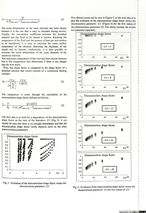
The first idea is to look for a dependence of the dimensionless shape factor on the ratio o f the diameters G l (Fig. 5). It can clearly be seen that there is no straight dependence and that the dimensionless shape factor surely depends more on the other dimensionless parameters.
Fig. 5 : Evolution o f the dimensionless shape factor versus the dimensionless parameter Gl
Five distinct zones can be seen in Figure 5, so the next idea is to plot the evolution o f the dimensionless shape factor versus the dimensionless parameter G2 (Figure 6) for the five values of the dimensionless parameter G3. For clarity reasons, the results are presented separately.
l
0.8
0.6
0.4
0.2
0
D im ensionless shape factor om ooo o o
G ì = 4
G2
0.8
0.6
D im ensionless shape factor
a t §
4 ( # 9
6
0.4 G ì = 12
20 40 60 80
l
0.8
0.6
0.4
0.2
0
D im ensionless shape factor
G ì = 16
20 40 60 G 2 t
Fig. 6 : Evolution o f the dimensionless shape factor versus the dimensionless parameter G2 for five values of G ì
It can be seen that there is a large difference between the actual shape factor and the one that could be calculated assuming that the heating element is a continuous cylinder.
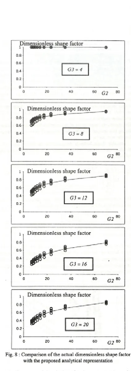
To analytically represent the results the following equation is proposed (solid lines in Figure 8):
S = a(G 3) Ln(G2) + b(G3) , (4)
with:
a(G 3) = -0.000839 G32 + 0.0337 G 3-0.120,
b(G3) = 0.00354 G32 -0.157 G3 + 1.572.
It can be seen that there is a good agreement between the proposed representation and the actual values o f the dimensionless shape factor.
The expressions o f a(G 3) and b( G3) are approximations of heuristic values. Figure 7 shows the comparison: dots for heuristic values and solid lines for analytical approximations.
b(G 3) 0.25 a(G 3)
0.2
0.15
0.1
0.05
0
Fig. 7 : Representation o f the evolution o f the two dimensionless functions involved in the expression of the
dimensionless shape factor
It can be seen that the proposed expressions of a(G 3) and
b(G 3) fit very well the heuristic values.
It has to be noticed that for values o f G3 that are inferior to 4, the values of a(G 3) and b(G 3) are constant:
a(G 3) = 0,
b ( G 3 ) = l.
In that particular case, the coil is equivalent to a continuous cylinder.
l
0.8
0.6
0.4
0.2
0
D im ensionless shape factor OOBDCDg) <d
---%-G3 = 4
60 G2
i D im ensionless shape factor
0.8
0.6
0.4
0.2
0
G3 = 16
20 40
0 8
0.6
0.4
0.2
0
D im ensionless shape factor
G3 = 20
G2
Fig. 8 : Comparison o f the actual dimensionless shape factor with the proposed analytical representation
It is often assumed that the heat flux is constant at the surface o f an electrical heating element. The simulations that have been carried out to compute the internal shape factor allow the calculation of a non uniformity factor. It is proposed to define this non uniformity factor as follows:
f i _ Tmax outer diameter ^min outer diameter
T —T
1 max wire 1 mean outer diameter
Introducing equations (2) and (4) in equation (5), leads to the following expression:
This factor is null when the wire can be assimilated to a continuous cylinder, and should increase when the wire diameter is small compared to the pitch of the coil. So, it is informative to plot the evolution o f this factor versus the dimensionless internal shape factor (Fig. 9).
0.07 Non uniform ity factor
0.06
♦ ♦
0.05 ♦ ♦
♦ ♦ ♦ ♦
V
♦ ♦0.03 4 + ♦
0.02
0.01
________
0.2 0.4 0.6 0.8 1
D im ensionless internal shape factor
Fig. 9 : Evolution o f the non uniformity factor versus the dimensionless internal shape factor
It can be seen that the non uniformity is limited to 6%, and that in most cases, it is inferior to 1%.
Now that the analytical expression o f the dimensionless shape factor is established, it is possible to present examples.
a p p l i c a t i o n s
? =
-Ln(G
l)---2ki v a(G 3)L n(G 2) + b(G 3) 2 k, Ln[A ' U , / + —
h
Then it can be said that the lowest value has to be chosen for G l, but technological constraints lead to the following relation: D, max = D j - 2 Dw . From Figure 8, it can be concluded that the
lowest value of G3 has to be chosen. Then it is possible to plot the evolution of q versus the wire diameter (Figure 10).
Fig. 10 : Evolution o f the heat flux per unit surface versus the wire diameter
It can be concluded that the heat flux does not depend a lot on the wire diameter. Taking a wire diameter inferior to 1.5 mm,
the safe value would be q = 19,000 W/m2 .
High temperature air heater
In this example, it will be supposed that air has to be heated at 1,000°C and that the maximum wire temperature is 1,200°C. The application o f the proposed equations will lead to the calculation of the maximum heat q that it will be possible to deliver per unit surface o f sheathed heating element.
It is necessary to assume other numerical values:
- convection coefficient: h = 100 W/m2K , - element outer diameter: De = 16 mm ,
- sheath thickness: t = 1 mm ,
- sheath material thermal conductivity: k , = 15 W/mK ,
- insulation material thermal conductivity: kt = 10 W/mK .
In that case, the dissipated heat flux may be written as follows:
High heat flux water heater
In this example, it will be supposed that water has to be heated
at 100°C and the heat flux should be q = 1,000 kW/m2 . The application of the proposed equations will lead to the calculation o f the maximum temperature o f the wire. Here again, it is necessary to assume other numerical values:
- convection coefficient: h = 10,000 W/m2K , - element outer diameter: De = 16 m m,
- sheath thickness: t = 1 mm ,
- sheath material thermal conductivity: k , = 15 W/mK ,
- insulation material thermal conductivity: kt = 10 W/mK .
In that case, the maximum temperature of the wire may be written as follows:
T ■ - T ■ J m a x w i r e 1 a i r
* D e P
+ ^ e Ln
f
Df
L 'Sk i 2 k, h
(5) • = 9' x D e p I D ‘ I n f ' 1 S
{ Ski ' 2 k ~ \ D e - 2 tJ h + .. (6) Introducing equations (2) and (4) in equation (6), leads to the following expression:
□ 1 - s
k thermal conductivity [W/mK]
f De I n ( G I ) . 1 P pitch o f the coiled wire [m]
2 kj a (G 3)Ln(G 2) + b(G 3) ' Q heat rate [W]
° e L n
r
a .i
14- T 1 waterT •
<7 heat flux [W/m2]
2 k, D . - 2 t ' h s shape factor [m]
\ 3
So reference shape factor
technological constraints lead to a maximum (for a continuous heating cylinder) [m] o f about 650°C (Figure 11). Š dimensionless shape factor
t thickness o f the sheath
Greek Sym b ols
S non uniformity factor
Subscripts
e sheathed element i insulation material s sheath
t torus
R E F E R E N C E S
Daurelle, J.-V., 1990, Internship report, VULCANIC
Fig. 11 : Evolution o f the maximum temperature o f the wire
versus the wire diameter Thibault, P., 1991, Internship report, VULCANIC
It can be concluded that there is no risk o f melting.
C O N C L U S IO N S
Simulations o f the heat transfer in a sheathed electrical heating element has led to an analytical expression o f the internal shape factor. This allows the prediction o f the maximum temperature of the heating wire for a given heat flux, or the maximum heat flux for a given wire temperature. These simulations have allowed the calculation o f a non uniformity factor. It has been shown that this non uniformity factor is, in most cases, inferior to 1%. Future studies will address straight wires sheathed elements.
Lalot, S., 1994, Etude d'un Réchauffeur Electrique pour Fluides Corrosifs, These de doctorat, Université de Valenciennes et du Hainaut Cambrésis
SYSTUS International, 1999, Systus+ user's manual
A C K N O W L E D G M E N T S
This study was partially sponsored by SYSTUS International and by VULCANIC (major French manufacturer o f electrical heating elements).
N O M E N C L A T U R E
a function in equation (4)
b function in equation (4)
D diameter [m]
Gl ratio o f the outer diameter o f the insulation material to the mean diameter o f the torus, Dt /D ,
G2 ratio o f the outer diameter o f the insulation material to the diameter of the wire, Dt / D w
G3 ratio o f the coil pitch to the diameter o f the wire,
p / D w
h convection coefficient [W/m2K]