Mathematical Modeling and Experimental Verification of
Operating Parameters of Vane Pump with Double Effect
Radovan Petrović *
University of Kragujevac, Faculty of Mechanical Engineering Kraljevo, Serbia
In developing the vane pumps the fundamental basis is experimental research and mathematical modeling of transient hydraulic processes inside the pump, in thrust space and suction and thrust pipeline. By means of experimental research and results of mathematical modeling and software package KRILP, it is possible to determine the parameters of operating processes of vane pumps precisely enough.
© 2009 Journal of Mechanical Engineering. All rights reserved.
Keywords: hydraulic pumps, mathematical modeling, hydrodynamics
0 INTRODUCTION
Modern methods of designing and constructing the hydraulic pumps cannot be done without using the appropriate mathematical models of effects and processes happening in real pump structures. The mathematical model of a process is analytical interpretation of the process with certain assumptions. In order to reach the mathematical model it is necessary to make detailed theoretical research based on the laws of fundamental sciences and explanation of processes, what is the basis for adopting the
assumptions and defining the modelequations [1]
to [7].
1 MATHEMATICAL MODEL OF PRESSURE CHANGE IN THE OPERATING CHAMBER
The level of noise made by vane pump with double effect is crucially influenced by pressure rise and fall in the pump chambers in the areas of change of operating cycles. Constant conversion of thrust pressure into operating pressure in the installation and vice versa is an important assumption for lowering the noise
level. There are a great number of researches
done in order to define the optimum geometry of working volume when one operating cycle converts into another one [9]. The processes occuring at the area of pressure change and their relation can be researched by experiments and by mathematical modeling by means of adequate software packages. For these researches the software KRILP has been developed and it has been written in program language Digital Visual Fortran 5.0.
The increase of rotation speed provides
better tightness of working chamber at the area of pressure change which can be explained by the increase of centrifugal force acting on the vanes and pressing them against the inner surface of the stator. When the vanes are separated from the operating stator profile, pressure pulsation and amplitude changes are registered [10]. These changes often occur with low number of revolutions and they lead to oil coming back from thrust area towards suction area. When chambers are not sealed tight, i.e. when clearances are large, the pressure does not rise enough in the area of pressure change, what leads to unexpected relation between the chamber and thrust port and also leads to pressure balance. Thus the leakage between the suction and thrust zone is being increased as well as the amplitude of pressure pulsation.
Due to the influence of the clearance on the tightness in the chamber, the pressure change in the chamber should be presented by mathematical model depending on volumetric losses and it is necessary to make certain simulations on the computer. On the basis of data obtained by experiments and simulations one should determine geometries of suction and thrust ports as well as partitions between them at valve plate. The following phases can be distinguished in simulating the pressure change in the chamber while passing over the partition separating suction and thrust zones [8]:
- the chamber is closed, i.e. there is no connection between the chamber and neither suction zone and nor thrust zone,
- the chamber is connected to thrust port through the slot,
To steering gear
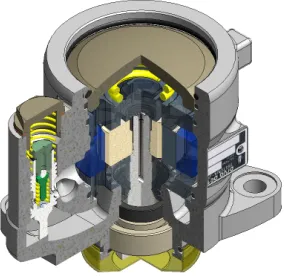
From reservoir Vane pump with double effect is shown in Fig. 1 and Fig. 2.
Technical data:
• Speed: 1500 r.p.m.
• Pressure: 21 MPa
• Flow: 62 l/min
• Number of vanes: 10
Fig. 1. Vane pump with double effect made by Prva Petoletka Trstenik, Serbia
Fig. 2. Quarter section of the vane pump with double effect
1.1 Volumetric losses affecting the speed of pressure change in the operating chamber at the zone of pressure change
In order to operate properly the pump must have appropriately clearances between vane rotor and valve plates. There is a certain flow through these clearances. Volumetric losses in the chamber can be classified as follows [8]:
• losses at vane side made by axial clearances
Qan (n=1.2)
• losses over vane top made by radial
clearances Qrn(n=1.2)
• losses made by flow withdrawal Qpr
• losses through the slot at valve plate Qpz
•
losses through the gap made by the vane inrotor groove Qpc
1.1.1 Losses Made by Axial Clearances
If we assume that the flow is streamline,
the losses through the axial clearances are: a) volumetric losses for the chamber in front of
the vane can be presented by following equation:
), p sign(p p p ηs
z r) (ρ
Qa a r− k r− k
⋅ − =
12
3 1 1
(1)
b) volumetric losses for the chamber behind the vane can be presented by following equation:
), p (p s 12η
z r) (ρ
Q k u
3 a2
a2 −
⋅ − =
(2) where:
ρ- variable radius of the stator
r - smaller radius of the stator
za , za2 - values of axial clearance
s - vane thickness
η- dynamic viscosity of working fluid
pu - suction pressure
pk - pressure in the chamber
pr - operating pressure
1.1.2 Losses Made by Radial Clearances
Between the inside surface of the stator and vane top working flow leaks what can be presented as follows:
a) volumetric losses for the chamber in front of the vane can be presented by following equation:
), p sign(p p p s 12η
z b
Q r k r k
3 r1
r1 − −
⋅ =
(3) b) volumetric losses for the chamber behind the vane can be presented by following equation:
), p (p s 12η
z b
Q k u
3 r2
r2 −
⋅ =
(4)
zr1, zr2- values of radial clearances
1.1.3 Losses Made by Flow Withdrawal
The mean value of losses made by flow withdrawal at the vane is presented by the expression: 4 r) r)(R ω(R z
Q a1/2
pr − + = , (5) where are:
ω - angular speed of rotor, φ - angle of rotor rotation,
R,r - bigger and smaller radius of stator.
1.1.4 Losses Through the Slot at Valve Plates
Losses through the slot in thrust port at valve plate are determined in the following manner: ) p )sign(p p (p ρ 2 μA
Qpz= r− k r− k ,
(6) where are:
μ - outflow coefficient,
A - cross-sectional area, ρ - density of working fluid.
1.1.5 Losses Made by the Vane in Rotor Groove
If the pressure in the chamber is higher than working pressure of the pump there is a gap in rotor groove made by front vane tilting because of tangential load and there is oil leakage which can be presented by:
) ( 12 3 r k r pc
pc p p
l bz
Q = −
η , (7)
where are:
pc
z - clearance in the gap,
)
( r
r l r r
l = − − - length of the front vane when
rotor is in transmission area.
1.2 Speed of pressure change in the chamber when suction and thrust zones are being separated
If initial volume V is reduced for
),
( 1
1 V V V
V
dV = − =− − due to pressure rise
dp = p1 - p the relative volume -dV/V, calculated
per pressure unit:
, V dV dp
1 S=− ⋅
(8) is compressibility coefficient.
The reciprocating value of compressibility coefficient is called the compressibility modulus:
εS=
V / dV
dp S
1 =−
(9) which has the same dimension as the pressure.
In previous expressions the minus sign shows that pressure rise corresponds to volume decrease and vice versa. The previous expression can be also presented in the following form, in case of final changes of pressure and volume:
S p V V ε Δ = Δ − (10) which represents so called Hooke's law. The marks in previous expression are:
p p p= −
Δ 1 - pressure increment,
V V V = −
Δ 1 - change of volume,
V1 - fluid volume at the pressure p1.
The pressure increment in the working chamber of vane pump with double effect can be reached from the following expression:
, ) ( ( ) ) ( R k R k s k V V p = Δ
Δ ε
(11) where are:
Δpk - pressure increment in the chamber
between the vanes pu<pk<pp,
εS - compressibility modulus of working fluid,
pu - suction pressure of working fluid,
pp - thrust pressure of working fluid,
Vk(R) - volume of the chamber (when the
chamber is in the zone of pressure change constrained by angle ε and bigger stator radius
R).
Volume Vk(R) is calculated like this:
(
)
( ),2
2
2− β −σ
= r
k(R) R r
b V
(12) where are:
(β-σ) [rad] - angle between two adjacent vanes,
b - vane width.
( )
( ) k R
k s
k R
V p
t V t
Δ
Δ ε
Δ = Δ (13)
in case when Δt→0; ΔVk(R) → dVk(R) →0 and
Δpk →dpk →0, previous equation has
differential form:
) ( )
(
)
( kR
R k
s
k V
dt d V t
p = Δ
Δ
Δ ε
.
(14) If we put the expressions for volumetric losses (1) to (7) into the expression (14) for speed of pressure change in the chamber we obtain the following expression:
( k(R)
k s
a1 a2 r1
k(R)
dV dp ε
2Q 2Q Q dt =V dt + − +
)
pc pz pr
r2 Q Q Q
Q − + +
− . (15)
After replacing the values for volumetric losses we get required expression for speed of pressure change in relation to the clearance in the chamber of vane pump with double effect:
( )
( )
3 k(R)
k s a1
r k r k
k(R)
3 3
a2 r1
k u r k r k
3
a1/2 r2
k u
3 pc
r k r k k r
r
dV
dp ε (ρ r) z
2 p p sign(p p )
dt V dt 12ηs
(ρ r) z b z
-2 (p p ) p p sign(p p )
12ηs 12ηs
z ωR+r)(R - r
b z
- (p p
)-12ηs 4
bz 2
μA (p p )sign(p p ) p p
ρ 12 lη
⎡ − ⋅
= ⎢ + − −
⎢⎣
− ⋅ − + ⋅ − −
⋅
− +
⎤ ⎥
+ − − + −
⎥⎦
(16) Next section shows diagrams of speed of pressure change depending on the clearance in the operating chamber of vane pump with double
effect [11] to [16]. They are obtained by
simulation of expression (16) by means of software package KRILP.
2 RESULTS OF SIMULATING THE PRESSURE CHANGE IN THE CHAMBER OF
VANE PUMP WITH DOUBLE EFFECT
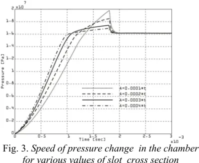
Results of simulating the expression for speed of pressure change in the chamber for various values of slot cross section are shown in
Fig.3.
Fig. 3. Speed of pressure change in the chamber for various values of slot cross section
Results of simulating the expression for speed of pressure change in the chamber for various values of axial clearance at the first vane are shown in Fig.4.
Fig. 4. Speed of pressure change in the chamber for various values of axial clearance at the first vane
Results of simulating the expression for speed of pressure change in the chamber for various values of axial clearance at the second vane are shown in Fig.5.
Fig. 5. Speed of pressure change in the chamber for various values of axial clearance at the
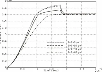
Results of simulating the expression for speed of pressure change in the chamber for various values of radial clearance at the first vane are shown in Fig.6.
Fig. 6. Speed of pressure change in the chamber for various values of radial clearance at the first
vane
Results of simulating the expression for speed of pressure change in the chamber for various values of radial clearance at the second vane are shown in Fig.7.
Fig. 7. Speed of pressure change in the chamber for various values of radial clearance at the
second vane
Results of simulating the expression for speed of pressure change in the chamber for various values of the gap in rotor groove are shown in Fig. 8.
3 EXPERIMENTAL VERIFICATION OF OPERATING PARAMETERS
Experimental verification of prototype operating parameters of vane pump with double effect type 641-4300L, firm PPT, Trstenik,
Serbia has been done at the Laboratory along with simulation of real conditions of pump exploitation.
Fig. 8. Speed of pressure change in the chamber for various values of the gap in rotor
groove
The following tests and diagrams have been made:
- dependence between the pump pressure and flow at constant speed of rotation of pump shaft, - dependence between the pump pressure and flow with oils of various kinematic viscosity at constant speed of rotation of pump shaft.
The testing has been done at universal test stand AMS ZI 108-94262 FRESNES(FRANCE) TIP BAH 1622/B38-5, Fig.9.
Fig. 9. Universal test stand AMS ZI 108-94262 FRESNES (FRANCE) TIP BAH 1622/B38-5
rise at thrust line and by closing the cock with keeping the constant rotation number the flow value is decreased for the value of losses made by the clearances at operating parts of the pump. The testing has been done with the oil of low kinematic viscosity (10 m2/s at 50 0C).
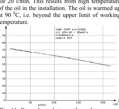
Fig. 10. Dependence between the outlet pressure and the flow of the pump (sample no.051)
The diagram at Fig. 11. shows that the flow value at the pressure of 20 MPa has fallen for 20 l/min. This results from high temperature of the oil in the installation. The oil is warmed up at 90 0C, i.e. beyond the upper limit of working
temperature.
Fig. 11. Dependance between the outlet pressure and the flow of the pump (sample no. 053)
The diagram at Fig. 12. shows the jamming of operating parts of the pump because the oil temperature reached the value of 100 0C.
The diagram at Fig.13. shows dependence between the outlet pressure and volumetric losses when oil of kinematical viscosity of 10 mm2/s has
been used at the temperature of 50 0C and when
oil of kinematical viscosity of 24 mm2/s has been
used.
Fig. 12. Dependence between the outlet pressure and the flow of the pump (sample no.054)
Fig. 13. Dependence between the outlet pressure and the flow of the pump with oil different
kinematic viscosity
We can notice the decrease of volumetric losses when testing the pump with the oil of higher kinematical viscosity.
4 CONCLUSION
It is not possible to determine precisely enough the parameters of hydrodynamic process of the vane pump with double effect neither by experiments nor by mathematical modeling only. Accurate working parameters can be reached by combined application of experimental measuring, mathematical modeling of hydrodynamic process and nonlinear optimization but at the same time the system errors of measuring and unknown parameters can be determined.
5 REFERENCES
[1] Petrovic, R. Mathematical modeling and
identification of multicylindrical axial
piston pump parameters. PhD Thesis,
Faculty of Mechanical Engineering,
Belgrade,1999.
[2] Jankov, R. Development of new
generation of ultra fast acquisition and
control system ADS 2000. Science and
vehicle, Belgrade.
[3] Čantrak, S., Glavčić, Z., Petrović, R. Modelling of transition process behind the local resistance depending on flow rate
circumference component. E17-E20 pp,
Third International Conference Heavy Machinery – HM ‘02, 27-30 October 2002, Kraljevo.
[4] Petrović, R., Jankov, R. Computer
program for mathematical modelling and identification of hydrodinamic processes
of a piston radial pump. E25-E28 pp,
Third International Conference Heavy Machinery – HM ‘02, 27-30 October 2002, Kraljevo.
[5] Glavčić, Z., Čantrak, S., Petrović, R. Analysis of flow energy losses in transition regimes of flow energetic
parameter. E17-E20 pp, Third
International Conference Heavy Machinery – HM ‘02, 27-30 October 2002, Kraljevo.
[6] Petrovic, R., Glavcic, Z. Systematic
research of characteristic parameters of the
piston axial pump . III International
Workshop on Computer Software for Design, Analysis and Control of Fluid Power Systems, septembar 2003. Ostrava-Malenovice, Czech-Republic.
[7] Petrović, R. Systematic research of
characteristic parameters of the piston
axial pump. Poster presentation, III
International Fluid Power Conference 5-6 March 2002, Aachen, Germany
[8] Axel F. Theoretical and experimental
research of resistance control at suction side
of force pumps. Dissertation RWTH
Aachen, 1995.
[9] Schwarz T. Analysis of sound in order to
diagnose damages of hydraulic pumps.
Dissertation RWTH Aachen, 1990.
[10] Draskovits G., Merz J. Vane pumps
controlled at suction side. Manuscript:
DE4209840 Schwäbisch Gmünd, 1993.
[11] Wüsthof P. Theories and measurements of
characteristic problems occurring in
hydrostatic vane pumps. Dissertation TH
Eindhoven, 1969.
[12] Tsung T.T. Analytical and experimental
research of hydraulic inductivity of ports
and orifices. Dissertation RWTH Aachen,
1991.
[13] Urlich H. Electrohydraulic control of
pressure by variable flow pump for various
consumers and pipelines. Dissertation
RWTH Aachen, 1993.
[14] Welschof B. Analytical research of applying
a hydraulic pump having damped suction line in order to control load. Dissertation RWTH Aachen, 1992.
[15] Will. D. Influence of oil temperature on
flow stability of throttle valves with special
reference to cavitation. Dissertation TU
Dresden, 1968.
[16] Backé W. Lecture on servohydraulic back