Development of a Part-Complexity Evaluation Model for
Application in Additive Fabrication Technologies
Bogdan Valentan* ̶ Tomaž Brajlih ̶ Igor Drstvenšek ̶Jože Balič University of Maribor, Faculty of Mechanical Engineering, Slovenia
With the rapid development and expansion of devices for the production of both traditional (cutting) procedures and layered technologies (also known as 3D printers or rapid prototyping/manufacturing), the question arises as to how to find the appropriate production technology.
Article describes the basic features of the CAD output file STL. The STL file format is a widely-used file format developed for layered technologies and, as such, a basis for analysing and developing methods when determining the complexity of a model.
For the analyses of basic STL data, and complexity determination, several real-life models are presented.
Actual manufacturing procedures suitable for the manufacture of unique products or serial production are presented, with accentuation towards layered technologies.
Technological test models are analysed based on the fundamental properties of manufacturing and certain manufacturing processes are chosen using complexity estimation. The results are comparable with those choices of manufacturing procedures on the basis of experts' estimates. Complexity evaluation is also used for post-processing time determination for several layered technologies.
©2011 Journal of Mechanical Engineering. All rights reserved.
Keywords: rapid prototyping, STL, complexity, shape, layered technology, technology choosing
0 INTRODUCTION
The development of production technologies started in the early years of human society and then expanded during the industrial revolution. Since then technologies have been refined, new versions introduced and with computer support we now have partial-automation. Production was optimized [1] and [2] in terms of becoming cheaper, faster and better. Basically, however, technologies are still based on old knowledge in terms of removing materials, casting or forming. In addition, technological restrictions are still present when the complexity of a product plays a key role and a selection process is necessary before making the product. In order to realize a project in manufacturing, people with knowledge and experience are needed and a combination of several different technologies in complex everyday products is common [3] and [4].
No serious players from the field of conventional cutting processes were interested when the origin of layered technology was first introduced in the middle of 1980's. The technology was expensive, complex, inaccurate,
slow, limited by the dimensions and materials [5, 6], but did allow the manufacturing of products in one piece, regardless of their complexity. Technology did have another advantage, the time for the preparation of input parameters did not depend on the complexity of the product. In the beginning technology has acquired the names rapid prototyping or 3D printing.
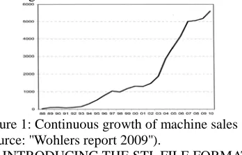
We could say that in the field of layered technologies we are still in the middle of constant growth [7] (Fig. 1) and because of, at least on paper, very promising new revolutionary innovations, a lot of people refer to the new industrial revolution when talking about layered technologies.
Figure 1: Continuous growth of machine sales (source: ''Wohlers report 2009'').
The STL data format is a polygonal (mesh) format developed for the needs of 3D Systems’ stereolithography equipment, which is one of the layered technologies. Stereolithography (U.S. Patent called ''Apparatus for Production of Three-Dimensional Objects by Stereolithography'') was patented in 1984 and in 1986 the 3D Systems Company began to manufacture devices for prototype production.
During this time, the STL file format [8-10] was adopted by all other layered technologies and as such became the standard format. The reason for the popularity of the STL file format is in the simplicity of model description, as the STL format describes only the external surface of the 3D model without adding any other data. Some CAD attributes (points, lines, curves and layers) in other formats (WRML, DXF) can cause complications in non-standard formats records [11, 12].
There are two formats of the STL file (binary and ASCII). The STL file format is supported by all modern CAD programs, although not all allow storage in both forms.
Since the STL file does not contain information about the real model size, some problems can appear such as unit change from cm to inch (SI replacement for the imperial system).
While exporting from the CAD to the STL file, part-resolution needs to be set. Export options are different in various CAD programs. The main parameters are set by the maximal allowed deviations between triangle mesh and the original CAD model, and the minimal allowed angle between two triangle’s edges.
When choosing model resolution, it is necessary to have in mind that the resolution of the manufacturing device can be greater than the STL resolution, and a lack of resolution means a lower surface quality for the model produced [13-15] (Fig. 2). The problem is frequently set into a production line where an outside contractor cannot know the desired surface quality. By increasing the precisions of production technologies, this problem shows the limitations of the STL format where, despite the most accurate resolution and large file size, a smooth surface cannot be achieved.
Figure 2 : Comparison between optimal and deficient choices for the export parameters of the STL file.
2 TEST PARTS
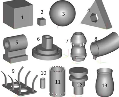
Some test parts were needed for evaluating the complexity. The limitations of the STL file were taken into consideration. For a realistic comparison, all models were designed using the same CAD software (Catia V5) with the same settings for exporting STL files (3D accuracy of 0.01 and curve precision to 0.1). All models were checked for errors and verified by the Netfabb [16] program, and appropriately placed into the positive coordinates of their own coordinate systems. Orientation is set by experience since, in normal cases, author starts modelling in one of the basic planes.
Three models of basic geometric shapes can be found among the selected test models, and all the rest are the real ''user'' parts (Fig. 3). An important fact is the presumption that complexity does not depend only on the shape of the model, but also on the size. Two models are the same shape but different sizes.
3 BASIC PARAMETERS OF THE TEST MODELS
Basic STL file parameters were used for the experiment, such as the size of the binary file, number of triangles, part’s volume, part’s surface (area), and the volume of the block that captures the model. All parameters can be obtained by reading the STL file. Some properties can be calculated using basic mathematical equations or by some advanced software tools that allow visualization of the model and its properties (for example Netfabb).
3.1 Determination of octants and problematic sections
A simple procedure for basic manufacturing procedure determination was used due to difficulty in determining the basic form [17-19] – shape recognition (statistically due to the loss of data when converting into STL format). Each model’s octants were determined by distributing a part’s external block into eight smaller blocks (octants) (Fig. 4).
Information about each octant, information on the overhangs and negative angles was gained from the vector’s direction, which normally constitutes a problem with conventional cutting processes during manufacture.
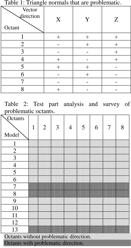
Table 1 shows the direction of a triangle’s normal vector that is problematic in each octant. It is enough to look at the sign of the triangle’s vector. If a problematic vector exists the part cannot be made by conventional procedure without an additional fixture or the use of special tools, but in most cases manufacturing using the conventional procedure (production in one piece) is impossible.
Figure 4: Octant distribution through the model.
If there is a case where octants 1 and 3, 2 and 4, 5 and 7, 6 and 8 are vectors of opposite directions (flipped through the centreline of the
model and the axis passing through the junction of octants 1, 2, 3 and 4 and continuing through junction of octants 5, 6, 7 and 8) the model can be suitable for rotary machining. All test models were analyzed for the vector directions in each octant. The results are presented in table 2.
Table 1: Triangle normals that are problematic. Vector
direction
Octant
X Y Z
1 + + +
2 - + +
3 - - +
4 + - +
5 + + -
6 - + -
7 - - -
8 + - -
Table 2: Test part analysis and survey of problematic octants.
Octants
Model
1 2 3 4 5 6 7 8
1 2 3 4 5 6 7 8 9 10 11 12 13
Octants without problematic direction. Octants with problematic direction.
4 COMPLEXITY DETERMINATION
Figure 5: Complexity based on expert opinion.
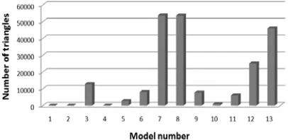
The complexity of the model can be deduced from information on the number of triangles (Fig. 6) (number of triangles is directly related to the size of the file). An increased number of triangles represent a more complex model. This comparison does not take into account the increasing complexity while decreasing the size of the model and all models shod be created with the same export parameters.
Figure 6: Number of triangles of the test models.
4.1 Advanced evaluation of model complexity
Complexity on the basis of file size or number of triangles presents us with some basic part complexity ideas, without the model’s size being taken into consideration. For example, with model’s 1 and 2, and 10 and 11, the calculated complexities should not be the same, since there are significant size differences between these parts. When reducing the size of a part, its complexity increase.
For accurate complexity calculation, the proportions of the three basic parameters of the model are needed: the model’s surface, number of the model’s triangles, and model’s volume.
(1)
Result of Equation 1 is presented in the following graph (Fig. 7). It can be seen that part size plays a significant role regarding complexity determination. This relationship taking into consideration part size is very similar to the complexity based on our own experiences.
Figure 7: Calculated complexity that can be compared with complexity given by experts
Calculated complexity of the model is comparable to experientially determined complexity (Fig. 5). Three models deviate from the average (7.8 and 13) all of them are having varied surfaces and are problematic for manufacturing using conventional procedures. A significant impact is also when reducing the scale of a model which results in an increase in the complexity (models 1 and 10 versus models 2 and 11).
5 MANUFACTURING PROCEDURES
Today’s manufacturing procedures are divided into conventional (cutting operations [22]) and layered technologies.
first presented and patented procedure – stereolithography.
Material application layer by layer is common to all technologies [25, 26]. Technology produces individual 2D layers and by adding 2D layers on top of each other (a 3D product is formed). Important information from the survey is that some procedures do support individual layers where necessary (overhangs or the spread of the model in a Z direction), as imposed support material, which is not the same as for models. In these cases, the form of the product affects the price, as well as the building time. In the end it should not be forgotten that all today’s known layered-technologies need some post-process to obtain a final part. This can be a simple cleaning procedure, the removal of support material or even infiltration with some special material, and all this costs time and money.
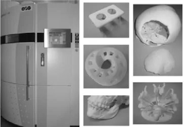
Figure 8: EOS Formiga P 100 Selective laser sintering (SLS) machine with some parts.
7 CHOOSING THE OPTIMAL MANUFACTURING PROCEDURE
Several criteria should be taken into consideration when selecting the appropriate manufacturing procedures:
- The desired material - The size of the product - The manufacturing time and - Cost of manufacture
This paper’s topic focuses on product design, which means that at this stage some properties are ignored, such as materials, materials’ properties, and product size, since material properties in the STL format are not given and size is not as problematic, since there are different machines for producing different sizes parts. Production is highly dependent on the
complexity of the product, especially when comparing cutting processes and layered techniques.
7.1 Choice on the basis of vector direction in each octant
Table 3 presents the results of selection on the basis of determining vector direction in each octant. Turning is chosen as the most affordable process when it comes to a rotary piece (models 3, 6 and 12), milling when it comes to the model without problematic vectors that define impossible tool angles and layered technology for all other models.
Layered technologies are divided into two subcategories:
• Layered technologies that for support using raw modelling material. In this case, the support material can be reused and it does not represent an additional cost.
• Layered technologies that using some additional support material at the part overhangs or have support from the model material, but that material should be removed after some treatment.
Table 3: Choosing the manufacturing procedure on an octant vector direction base.
Turning Milling
LT where support is needed
LT where support is not needed 1
2 3 4 5
6 Partly 7
8 9 10 11 12 13
Procedure is appropriate Procedure is inappropriate
7.2 The choice on the basis of the part complexity
the right procedure for manufacturing. Manufacturing by turning is only possible for models 3 and 12 (Table 4), which have a relatively low ratio of fewer than 20,000 and do not stand out (Fig. 7). By imposing a limit of 20,000, models 2, 4, 5 and 11 are added to the selection, even if the manufacturing of these models in this case, is impossible.
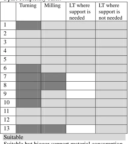
Table 4: Choosing a manufacturing procedure on a part-complexity basis.
Turning Milling LT where support is needed
LT where support is not needed 1
2
3 4 5
6 7
8 9
10 11 12
13
Suitable
Suitable but bigger support material consumption Unsuitable
Models, where the production with milling is impossible (7, 8 and 13) heave extremely high ratio (over 120,000). Models 6 and 9 are feasible to produce, but need an additional fixture during the manufacturing, or a complex 4 axes-production process. Models that are easy to produce have a low ratio (below 40,000). The limit for the milling process as the best possible selection was set at 100,000.
It can be seen that layered technologies are suitable for all models (From the point of manufacturing techniques, this is already a known fact), but when dividing technologies into those that need additional support material and those in which the support material is the same as the model’s material, it can be written that in the case of a model with higher complexity, the production costs are higher. The limit between those two
technologies was set to 50,000. So if complexity is below 50.000 any layered technology is suitable, when the complexity is beyond 50.000 layered technologies that reuse support material are more suitable.
Models (1 and 10) are problematic to produce as they are resized to extremely small dimensions and can create certain problems for both processes. In the case of milling, the problem of clamping exists and in the case of layered technologies, resolution of the technology itself presents an obstacle to production.
7.3 The arrangements by combining the complexities of the shapes and the vector direction, in each octant
By examining the results of both selection processes (one based on the vector direction in each octant and the other on the complexity of form), it can be established that, in some instances, each selection process can favour the process by which production is impossible. By combining the two methods those procedures that are inappropriate are eliminated. The Results are presented in Table 5.
Table 5: Choosing the manufacturing procedure by combining part complexity with the octant vector direction.
Turning Milling LT where support is needed
LT where support is not needed 1
2
3 4
5 6
7 8 9
10 11
12 13
Suitable
Figure 9: Diagram presents choosing procedure. First Turning is chosen, if part can be produced by turning. On the complexity base ruff decision between Milling and both layered procedures can be made, as presented. At the end fine selection with introduction of parameters, that are not written in to STL file is made.
8 POST-PROCESSING TIME DETERMINATION BY EVALUATION OF
MODEL COMPLEXITY
The time for post-processing is problematic, especially from the perspective of determining the final production costs of the model. The price consists of construction material, hardware hour costs; fixed costs, energy cost, staff cost and the cost of post-processing. So far assessment has been individually determined solely and empirically by using peoples’ experiences. With the introduction of complexity evaluation, the post-processing time can be calculated and planned during the production time.
The time for post-processing (Fig. 10) is of course distinguishable between the different technologies (Fig. 11), therefore, it is necessary to determine the individual impacts of complexity on time for each layered technology.
To do that some parts need to be build and post-processing time for those parts need to be measured. On a basis of that data function:
(2)
can be derived and average value X calculated. For all following parts time can be calculated:
(3)
Since post-processing time is based on manual work, this function can never be exact (especially, when more than one man is working at post-processing stage), but can give us fair estimation on time needed for that production step.
This procedure is suitable for time-determination in the cases of technologies that require manual removal of the support structure. This category includes: SLS, LOM, SLA, PolyJet, FSM, LENS, DMLS, SLM and EBM. In the cases of these processes, the removal of support material takes a certain time, depending on the complexity of the product itself. In the cases of SLS, LENS, DMLS, SLM and EBM, the removal of non-solidified base material is required. In the case of LOM technology the removal of material surrounding the product is needed. SLA and FDM are building supports from base-material and these supports need to be broken off at the end. PolyJet has supports from special support material that needs special water-jet treatment at the end of the process. In processes in which the support material is dissolved in liquid or the model is infiltrated with special liquids, post-processing does not depend on the complexity of design.
Figure 10: Time of post-processing for test models made using the LOM procedure on SOLIDO SD 300 Pro. Models 1 and 10 were too small to be produced by LOM technology.
Figure 11: Waste-material removal in LOM.
9 CONCLUSIONS
The presented method introduces a fairly good method of fundamental decision between turning, milling and layered techniques. Selecting an appropriate layered technology is not unambiguously determined; therefore choosing the optimal layered technology can only be approximate. The reason for this lies in the sentence that is used in the marketing of layered technologies: ‘complexity for free''. The layered technologies of today have no problems with production of highly complex forms, which is also their biggest advantage over conventional procedures. This poses a certain problem when selecting a production procedure based only on the complexity of the product.
Shape affects only a few specific technologies from layered technologies either because of expensive support material (PolyJet, SLA, SGC, MJM), or the difficulty of removing the support material from the problematic sections (LOM).
On the other hand, the determining of the design complexity and the calculation of model resolution can mean certain selections regarding production procedure choice, where less-accurate parts can be made using less-accurate technology.
Evaluation of the complexity was proven when determining the time required for finalizing the product. This time of post-processing was quite difficult to determine since manufacturers would prefer to miss it, even though the impact on the time of manufacture is significant. When the talk is about rapid prototyping, time is one of the most important things. The presented solution is suitable for introducing into production.
This survey is a significant advance in the direction of process selection, but for practical applications it would be necessary to include more parameters and advanced selection methods [27-29], so that the process can be uniqly selected.
Only then after choosing basic part properties (like material properties, colour and surface quality), time of manufacture, dimensions, number of pieces in a series and the complexity, of doe’s product come into regard.
10 REFERENCES
[1] Balic J, Kovacic M, Vaupotic B. Intelligent programming of CNC turning operations using genetic algorithm. JOURNAL OF INTELLIGENT MANUFACTURING Volume: 17 Issue: 3 Pages: 331-340 Published: JUN 2006
[2] Kovacic M, Balic J, Brezocnik M.: Evolutionary approach for cutting forces prediction in milling. JOURNAL OF
MATERIALS PROCESSING TECHNOLOGY Volume: 155 Special
Issue: Part 2 Sp. Iss. SI Pages: 1647-1652 Part: Part 2 Sp. Iss. SI Published: NOV 30 2004
[3] Jurisevic B, Valentincic J, Blatnik O, et al.. An alternative strategy for microtooling for replication processes. STROJNISKI VESTNIK-JOURNAL OF MECHANICAL ENGINEERING Volume: 53 Issue: 12 Pages: 874-884 Published: DEC 2007
them. STROJNISKI VESTNIK-JOURNAL OF MECHANICAL ENGINEERING Volume: 54 Issue: 6 Pages: 426-445 Published: JUN 2008
[5] Campbell I, Combrinck J, de Beer D, et al. Stereolithography build time estimation based on volumetric calculations. RAPID PROTOTYPING JOURNAL Volume: 14 Issue: 5 Pages: 271-279 Published: 2008
[6] BRAJLIH, Tomaž, DRSTVENŠEK, Igor,
KOVAČIČ, Miha, BALIČ, Jože. Optimizing
scale factors of the PolyJet TM rapid prototyping procedure by genetic programming. J. Achiev. Mater. Manuf. Eng., May-Jun. 2006, vol. 16, iss. 1/2, str. 101-106.
[7] Wohlers Terry. Wohlers report 2009. Wohlers associates, USA 2009
[8] Wikipedia,
http://en.wikipedia.org/wiki/STL_%28file_f ormat%29 – STL file format description. Accessed 4. 3. 2010
[9] STL (stereolithography) Files, STL file description,
http://www.stereolithography.com/stlformat. php, Accessed 4. 3. 2010
[10] Liu F, Zhou H, Li D.Repair of STL errors. INTERNATIONAL JOURNAL OF
PRODUCTION RESEARCH Volume: 47 Issue: 1 Pages: 105-118 Published: 2009
[11] Sun Y, Li Z. VRML-based slicing software in rapid prototyping. 2008 PROCEEDINGS OF INFORMATION TECHNOLOGY AND ENVIRONMENTAL SYSTEM SCIENCES: ITESS 2008, VOL 2 Pages: 1213-1216 Published: 2008
[12] Chu CH, Wu PH, Yuan G. Online parametric configuration of three-dimensional product visualization based on a triangulation model. PROCEEDINGS OF THE INSTITUTION OF MECHANICAL ENGINEERS PART B-JOURNAL OF ENGINEERING
MANUFACTURE Volume: 223 Issue: 3 Pages: 231-246 Published: MAR 2009
[13] Yang Y, Fuh JYH, Loh HT, et al., Minimizing staircase errors in the orthogonal layered manufacturing system, IEEE
TRANSACTIONS ON AUTOMATION SCIENCE AND ENGINEERING V: 2 I: 3 P: 276-284, 2005
[14] Ahn DK, Lee SH. Improving the surface roughness of SL parts using a coating and
grinding process. INTERNATIONAL JOURNAL OF PRECISION
ENGINEERING AND MANUFACTURING Volume: 8 Issue: 3 Pages: 14-19
Published: JUL 2007
[15] Kopac J, Krzic P. CAM algorithm as important element by achieving of good machined surface quality. STROJNISKI VESTNIK-JOURNAL OF MECHANICAL ENGINEERING Volume: 54 Issue: 4 Pages: 280-287 Published: APR 2008
[16] www.netfabb.com NetFabb is a free tool for STL file analysis and manipulation Accessed 4. 3. 2010
[17] Balic J, Klancnik S, Brezovnik S. Feature extraction from CAD model for milling strategy prediction. STROJNISKI
VESTNIK-JOURNAL OF MECHANICAL ENGINEERING Volume: 54 Issue: 5 Pages: 301-307 Published: MAY 2008
[18] Sunil VB, Pande SS, Automatic recognition of features from freeform surface CAD models, COMPUTER-AIDED DESIGN V: 40 I: 4 P: 502-517, 2008
[19] Qu XZ, Stucker B, Circular hole recognition for STL-based toolpath generation, RAPID PROTOTYPING JOURNAL V: 11 I: 3 P: 132-139, 2005
[20] Jarek Rossignac. Shape complexity. The Visual Computer, Springer Berlin / Heidelberg. Volume 21, Number 12 / December, 2005
[21] B. Valentan, T. Brajlih, I. Drstvensek, J. Balic. Basic solutions on shape complexity evaluation of STL data. Journal of
Achievements in Materials and
Manufacturing Engineering, VOLUME 26, ISSUE 1,Januar 2008
[22] Balič J., Veža I., Čuš F. Advanced manufacturing technologies (Napredne proizvodne tehnologije). Maribor : Faculty of mechanical engineering, Split : Faculty of Electrical Engineering, Mechanical Engineering and Naval Architecture, 2007
[23] Drstvenšek I. (ur.) Layered Technologies. Slovenia, Maribor, Faculty of mechanical engineering Maribor, 2004
[24] VALENTAN, Bogdan, BRAJLIH, Tomaž, DRSTVENŠEK, Igor, SEVER, Peter,
Valentan B., Brajlih T.,Drstvenšek I., Balič J.
1
production. Adv produc engineer manag,Nov. 2009, vol. 4, no. 4, str. 197-206. http://maja.uni-mb.si/files/APEM/APEM4-4_197-206.pdf. [COBISS.SI-ID 13599510]
[25] Sustarsic B, Dolinsek S, Jenko M, Leskovsek, V., Microstructure and Mechanical Characteristics of DMLS Tool-Inserts, MATERIALS AND
MANUFACTURING PROCESSES Volume: 24 Issue: 7-8 Pages: 837-841 Published: 2009
[26] Pilipovic A, Raos P, Sercer M. Experimental analysis of properties of materials for rapid prototyping. INTERNATIONAL JOURNAL OF ADVANCED MANUFACTURING TECHNOLOGY Volume: 40 Issue: 1-2 Pages: 105-115 Published: JAN 2009
[27] Raffaeli R., Mengoni M., Germani M. A Software System for ''Design for X'' Impact
Evaluations in redesign Processes. STROJNISKI VESTNIK-JOURNAL OF MECHANICAL ENGINEERING Volume: 56 Issue: 11 Pages: 707-717 Published: NOV 2010
[28] Skorc G., Cas J., Brezovnik S., Safaric R. Position Control with Parameter Adaptation for a Nano-Robotic Cell . STROJNISKI VESTNIK-JOURNAL OF MECHANICAL ENGINEERING Volume: 57 Issue: 4 Pages: 313-323 Published: APRIL 2011
[29] Sibalija T., Majstorovic V., Sokovic M. Taguchi-Based and Intelligent Optimisation of a Multi-Response Process Using