0 INTRODUCTION
Ductile cast irons (DCIs) are finding use in a growing range of applications due to a beneficial combination of their properties, such as high ductility and toughness, good fatigue strength, excellent machinability, and the
ability to be cast into complex shapes [1]. However,
DCIs are simultaneously characterized by low
abrasion and erosion resistance [2]. Because of this,
their use under severe wear conditions is generally limited. Currently, much emphasis has been placed on the improvement of wear performances of the working surface of machine parts made of the DCIs. Most published works have been focused on surface modification methods with the use of fusion welding
technologies, such as surface melting [3] and surface
alloying processes [4]. Due to the ability to change a chemical composition of modified surface layers, the surface alloying process is an especially promising method to tailor surface properties of cast irons. An ideal source of heat for the above-mentioned surface treatment process is the laser beam having a uniform intensity distribution (a top-hat profile) [5] to [7].
In contrast, it is well known that high chromium white irons (HWIs) have excellent abrasive and
erosive wear resistance [8]. Their exceptional wear
performances result from a high-volume fraction of
hard proeutectic and/or eutectic M7C3 carbides and
a tough matrix [9]. Several researchers have reported
the formation of such composite structures during the surface alloying of different types of cast irons [10] to
[11]. However, little work has been done to investigate the formation of HWI surface layers on DCIs using laser-alloying systems that utilize both laser sources with the top-hat beam profile and a direct injection of an alloying powder into the molten pool.
Therefore, the aim of the present work has been to explore the potential of a laser-alloying system comprising a high power direct diode (HPDD) laser with the top-hat beam profile and a direct injection of an alloying powder into the molten pool for the fabrication of HWI surface layers on the DCI substrate.
1 EXPERIMENTAL PROCEDURE
1.1 Materials
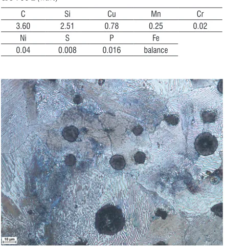
The substrate material (SM) used in this study was a DCI grade EN-GJS-700-2 with chemical composition shown in Table 1. The microstructure of the as-received DCI consists of a perlitic/ferritic matrix and
Fabrication of High Chromium White Iron Surface Layers on
Ductile Cast Iron Substrate by Laser Surface Alloying
Janicki, D.
Damian Janicki*
Silesian University of Technology, Faculty of Mechanical Engineering, Poland
High chromium white iron surface layers (HWSLs) have been produced on a ductile cast iron EN-GJS-700-2 substrate by diode laser surface alloying with a direct injection of a pure chromium powder into the molten pool. The main objective of this study was to investigate the effect of laser alloying parameters on the microstructural evolution in the HWSLs. The composition of the uniformly alloyed HWSLs contained up to 14.4 wt.% Cr. Both hypoeutectic and eutectic high chromium white iron microstructures were obtained. The type and morphology of eutectic carbides are affected by both the chromium concentration in the molten pool and the solidification conditions. With increasing chromium content, the fraction of eutectic regions in the hypoeutectic HWSLs increases and the eutectic carbides become progressively smaller. The rod-type morphology of the M7C3 eutectic carbides was dominant in the eutectic HWSLs. An average hardness of the HWSLs was influenced by the
size of carbide precipitations, and was 675 HV and 650 HV for hypoeutectic and eutectic compositions, respectively. Keywords: high chromium white iron, ductile cast iron, surface alloying, diode laser
Highlights
• The hypoeutectic and eutectic HWSLs were produced on a ductile cast iron EN-GJS-700-2 substrate by diode laser surface alloying with a pure chromium powder.
• The composition of the uniformly alloyed HWSL contained up to 14.4 wt.% Cr.
• The type and morphology of eutectic carbides are influenced by both the chromium concentration in the molten pool and the solidification conditions.
graphite spheres with an average diameter of 30 μm
(Fig. 1). Specimens of the SM were in the form of discs 60 mm in diameter and 10 mm thick. Prior to the alloying process, the specimens were ground to a
surface finish of 0.5 µm Ra and cleaned with acetone.
A chromium powder used as the alloying material has
a purity of 99.8 % and a particle size range of 40 μm to 90 μm.
Table 1. Chemical composition of the used DCI grade EN-GJS-700-2 (wt.%)
C Si Cu Mn Cr
3.60 2.51 0.78 0.25 0.02
Ni S P Fe
0.04 0.008 0.016 balance
Fig. 1. Microstructure of the used DCI grade EN-GJS-700-2
1.2 Laser processing
A continuous wave Rofin DL020 HPDD laser with a rectangular beam spot of size 1.5 mm × 6.6 mm and a uniform intensity distribution profile (the top-hat profile) was used for single-pass and multi-pass overlapping alloying trials. The beam profile of the used laser, measured with a Prometec Laserscope UFF100, is presented in Fig. 2. All alloying trials were performed in the fast-axis direction using a direct injection of the alloying powder into the molten pool via an off-axis powder injection nozzle. To provide a uniform powder distribution on the surface of the molten pool, the powder injection nozzle shape has been adopted to the laser beam spot (Fig. 3). The powder delivery system used had a feed rate accuracy of ± 0.5%. Argon was used as a shielding gas and was injected through a cylindrical nozzle at a flow rate of 8 l/min (coaxially with the powder stream).
Fig. 2. 2D beam profile of the used HPDD laser in the focal plane
a)
b)
Fig. 3. Diagram showing a) the alignment of the powder injection nozzle relative to the laser beam spot, and b) the geometry
of the powder injection nozzle opening used
effect of Cr concentration and solidification conditions in the molten pool on the microstructural evolution of the alloyed layers. All alloying trials were carried out without substrate preheating.
1.3 Metallographic Examination
Geometrical parameters of the SBs and multi-pass overlapping alloying layers were measured using an optical microscope and a Nikon NIS-Elements quantitative image analysis system. Microstructural analysis was performed using both an optical and a scanning electron microscope (SEM) equipped with an energy dispersive X-ray spectrometer (EDS). The fraction of eutectic regions in the microstructure of the HWSLs was measured using Carl Zeiss digital image processing software. The measurements were conducted on SEM images taken from the undersurface and mid-section of the alloyed layer, over a total area of the 8 mm² for each layer. The phase composition was determined by the X-ray diffraction (XRD) technique. Diffraction patterns were recorded using Co-Kα radiation (λ = 0.179 nm).
1.4 Hardness Testing
The HWSLs’ hardness was measured on polished cross sections with Vickers micro-indentation load of 200 g using Wilson Wolpert 401 MVD Vickers.
2 RESULTS AND DISCUSSION
2.1 Macro and Micro Analysis
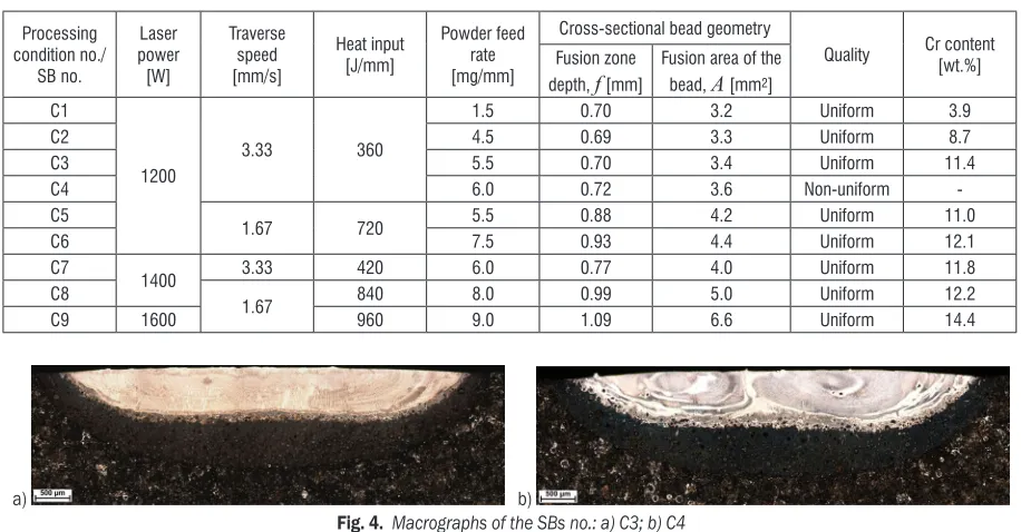
Fig. 4 shows cross-sectional macrographs of the SBs produced at a laser power of 1200 W, traverse speed of 3.33 mm/s (HI of 360 J/mm) and two levels of powder feed rate. The cross-sectional fusion profiles suggest that the molten pool had a negative surface tension temperature coefficient, meaning that the surface tension was greatest at the edges of the molten pool and lowest in the centre. In this case, the surface tension gradient induces fluid flow outward along the surface of the molten pool, producing the wide and shallow FZ. This shape of the FZ enables reducing overlap ratios during a multi-pass overlapping alloying process, limiting the overall HI. Moreover, it is important to note that the EDS line-scan analysis collected on cross-sections of the SBs has shown that the above-mentioned character of the fluid flow in the molten pool provides a homogeneous Cr distribution throughout the FZ even at relatively high powder feed rates (Fig. 5a).
It is clear that the MCP increases with an increase in the HI levels (Fig. 6). However, the data listed in Table 2 imply that the increase in the MCP does not provide a significant change in the Cr content in the SBs. This follows from the fact that the increase in the HI level leads simultaneously to progressively
Table 2. Selected processing parameters of the HPDD laser surface alloying process and geometrical parameters of the FZ of the SB and a total Cr content in the SB
Processing condition no./ SB no. Laser power [W] Traverse speed [mm/s] Heat input [J/mm] Powder feed rate [mg/mm]
Cross-sectional bead geometry
Quality Cr content [wt.%] Fusion zone
depth, f [mm]
Fusion area of the bead, A [mm2]
C1
1200
3.33 360
1.5 0.70 3.2 Uniform 3.9
C2 4.5 0.69 3.3 Uniform 8.7
C3 5.5 0.70 3.4 Uniform 11.4
C4 6.0 0.72 3.6 Non-uniform
-C5
1.67 720 5.5 0.88 4.2 Uniform 11.0
C6 7.5 0.93 4.4 Uniform 12.1
C7
1400 3.33 420 6.0 0.77 4.0 Uniform 11.8
C8
1.67 840 8.0 0.99 5.0 Uniform 12.2
C9 1600 960 9.0 1.09 6.6 Uniform 14.4
a) b)
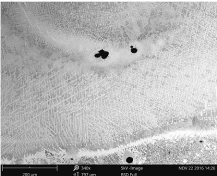
higher fusion areas of the SB (Table 2). As a result, the maximum amount of Cr which can be introduced into the molten pool during fabrication of the uniformly alloyed SB, in the used range of the HI, was found to be approx. 14.4 wt.%. The increase of powder feed rate above the MCP for the given HI level led to a non-uniform composition (Fig. 5b) and microstructure in the SB as a consequence of incomplete mixing in the molten pool (including an incomplete dissolution of graphite nodules, Fig. 7). The chromium powder capture efficiency, which in the laser-alloying process with an off-axis powder injection system depends directly on the size of the molten pool, was estimated to be in the range of 40 % to 50 %. Typical dimensions of the uniformly alloyed SB were width of approx. 6 mm and fusion depth in the range of 0.7 mm to 1.09 mm.
Fig. 6. Effect of the HI level on the MCP
The typical cross-sectional macrograph of the HWSL produced at the HI level of 720 J/mm and the powder feed rate of 5.5 mg/min (HWSL no. H4, Table 3) is presented in Fig 8. The microstructural parameters of the selected HWSLs produced at the optimal range of processing parameters are summarized in Table 3. As a result of the specific FZ geometry of the SB (wide and shallow), the uniform thickness of the HWSL was achieved at a low overlap
ratio of 30 %. The thickness of the fabricated HWSLs, which directly depends on the used HI level, was in the range of 0.7 mm to 1.1 mm. Generally, the HWSLs produced in the optimal range of processing parameters have uniform microstructures and no porosity. Due to the leak of preheating, all HWSLs possessed a crack network. The cracks propagated perpendicularly to the fusion boundary (FB) and did not affect the structural integrity of the alloyed layers. The cracking propensity of the HWSLs was found to decrease with increasing Cr content.
Fig. 7. Low magnification SEM image showing the non-uniformity in the microstructure on the cross-section of the SB no. C4
Fig. 8. Macrograph of the HWSL no. H4
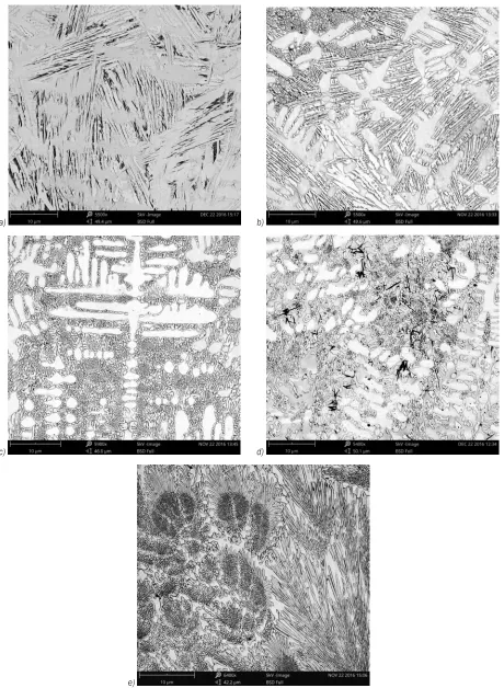
The metallographic data, presented in Table 3, indicate that the HWSLs having up to 12 wt.% Cr contents exhibited the hypo-eutectic microstructure (Figs. 11a to d). Higher Cr contents in the molten
a) b)
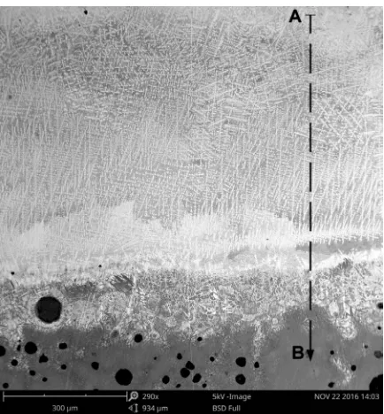
pool led to a formation the eutectic microstructure (Fig. 11e). A low magnification cross-sectional SEM micrograph of the hypo-eutectic HWSL no. H3 is presented in Fig. 9. Fig. 10 shows the EDS line-scan analysis of Cr concentration across the FZ (depth profile) of the above-motioned HWSL. The FZ can be divided into two layers: a layer with constant Cr content and a very thin layer directly adjacent to the FB exhibiting a gradient distribution of chromium. The thickness of the layer with the gradient Cr distribution decreases with the increase in the HI level and ranged from about 150 µm to 20 µm. The microstructure
of this layer is composed of primary austenite (γp)
grains partially transformed into martensite and a
network of the ledeburite distributed between the γp
grains. Graphite nodules surrounded by ledeburite shells are also present in this layer. Cross-sectional SEM micrographs taken from the mid-section of the selected HWSLs, produced in the range of optimal processing parameters (Table 3), are shown in Fig. 11. In general, the hypo-eutectic microstructure of the
HWSLs contains primary γp dendrites and eutectic
regions composed of eutectic carbides (M3C or M7C3
depending upon the chromium content) and the eutectic austenite phase (γe). Non-equilibrium cooling conditions in the molten pool and a chromium addition suppress the martensitic transformation [12] and [13]. In consequence, martensite needles were not observed in the γp dendrites. However, as can be seen in Figs. 11a and d the eutectic austenite phase in the HWSLs with low chromium contents (~4.0 wt.%) or produced at low solidification rates are partially transformed
into martensite. The γp dendrite growth generally
occurs at a faster rate in the direction perpendicular to the FB. This is because the SM (solid) acts as a heat sink. As a result, during solidification in the molten pool, cooling mostly occurs via the substrate, which brings about the directional growth of the γp dendrites counter to the heat flow direction (Fig. 9). An increase of the traverse speed, at constant powder feed rate, leads to a refinement of the γp dendrites. An average spacing between secondary dendrite arms varied from
2.5 µm to 1.6 µm, at traverse speeds of 1.67 mm/s and 3.33 mm/s, respectively (processing conditions no. C3 and C5, respectively, Table 2).
Fig. 9. Low magnification SEM image of the microstructure of the hypo-eutectic HWSL no. H3
Fig. 10. Chromium concentration profile on the cross-section of HWSL no. H3; profile taken along the line marked in Fig. 9
The type and morphology of eutectic carbides in the hypo-eutectic HWSLs depend both on the Cr concentration in the molten pool and on solidification conditions. In the HWSL with Cr content of about 4.0 wt.% (no. H1, Table 3), only the eutectic carbides
of the M3C type was present. In turn, when the Cr
Table 3. Processing parameters of the multi-pass overlapping alloying process and the HWSLs’ microstructural characteristics
HWSL no. Processing condition no. (Table 3)* Structure of the HWSL Cr content in the HWSL [wt.%] Type of eutectic carbide Fraction of eutectic region [vol.%] Dendrite cores Eutectic regions Total
H1 C1 hypoeutectic 1.9 3.5 4.1 M3C 54.5±2.9
H2 C2 hypoeutectic 5.4 10.3 9.2 M3C+M7C3 66.6±2.4
H3 C3 hypoeutectic 7.7 13.5 11.6 M7C3 72.5±2.5
H4 C5 hypoeutectic 6.0 13.9 11.4 M7C3 78.6±3.5
H5 C8 eutectic - - 12.6 M7C3 ~100
a) b)
c) d)
e)
content was higher than about 10 wt.%, the eutectic
regions were composed completely of γe+ M7C3.
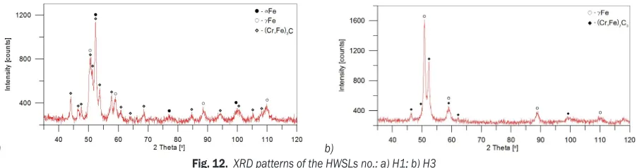
Representative XRD patterns for the HWSLs exhibiting the above-mentioned two modes of solidifications (HWSLs no. H1 and H3) are depicted in Figs. 12a and b, respectively. The XRD pattern for the HWSL no. H1 gave peaks which can be identified as belonging to the following: γ-Fe (fcc) phase, M3C
(M = Cr, Fe) and α-Fe (bcc) phase. The α-Fe (bcc)
picks suggest the partial austenite to martensite transformation. In contrast, the XRD analysis of the
HWSL no. H3 confirmed the presence of γ-Fe (fcc)
phase and M7C3 (M = Cr, Fe) carbides.
As expected, the volume fraction of the eutectic regions increases with increased total Cr content. Additionally, the data presented in Table 3 imply that the volume fraction of the eutectic regions, at constant Cr content, is affected by the traverse speed and HI level, that determine solidification conditions in the molten pool. Quantitative analysis of micrographs of the HWSLs no. H3 and H4, that is, having similar Cr contents (~11.5 wt.%), indicated that the increase in the traverse speed from 1.67 mm/s to 3.33 mm/s resulted in the reduction of the total fraction of the eutectic regions from approx. 78.6 vol.% to 72.5 vol.%, respectively. Taking into account that the above-mentioned change in the traverse speed simultaneously led to the decrease in the HI level, it can be considered that the fraction of the eutectic carbides increases with a decrease of solidification and cooling rates, as a consequence of the change in the microsegregation. This is consistent with SEM/
EDS analysis which revealed that the γp dendrites
become depleted in chromium with the decrease in solidification and cooling rates (Table 3). The total fraction of the eutectic regions in the HWSL with the lowest Cr content (~4.0 wt.% Cr) was measured to be approx. 54.5 vol.%. This implies that in all hypo-eutectic HWSLs the eutectic regions formed a continuous network surrounding the γp dendrites.
Generally, the γe + M3C eutectic has the ledeburite
structure (Fig. 11a). The increase in the Cr content
leads to the refinement of the M3C plates (Fig. 11b).
The M7C3 carbides exhibit both the rod-type and
blade-type morphologies (Fig. 11c). As in the case
of M3C carbides, with increasing Cr content the
M7C3 precipitations become progressively smaller.
Additionally, as can be seen in Figs. 11c and d, at constant Cr concentration in the molten pool, lower cooling and solidification rates promote a coarsening of M7C3 carbides. Since the eutectic carbides in the
hypo-eutectic HWSLs grow around the pre-existing γp
dendrites, their growth directions are affected by these dendrites. As a result, the orientation of the eutectic carbides varies with the heat-flow direction.
The eutectic HWSL (no. H5, Table 3) shows the eutectic microstructure (γe + M7C3) throughout the
entire layer with constant Cr content (Fig. 13). In this microstructure, the M7C3 type eutectic carbides grow
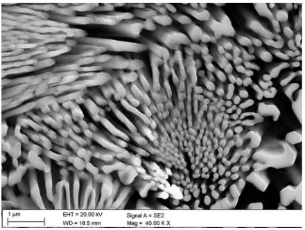
as eutectic colonies (Fig. 11e). The M7C3 carbides
within the eutectic colony are fine rod-like (fibrous) at the centre region of the colony and become slightly coarser and blade-like at the edge of the colony (Fig. 14). Simultaneously, with increasing distance from the centre of the colony, the volume fraction of the carbides decreases. This morphology of the eutectic colony indicates that the solidification begins in the centre with a certain level of undercooling and proceeds radially outward. The progress of solidification leads to a drop in the undercooling and, consequently, to the formation of coarser carbides in the last stage of the eutectic colony growth process. An average diameter of the carbide rod at the centre of the eutectic colony was approx. 180 nm. The diameter of the eutectic colony varied within the range from 4 µm to 10 µm. Based on the quantitative analysis of micrographs of the HWSL no. H5, the volume fraction of the carbides in eutectic colonies was estimated to be approx. 52 ± 4.5 %.
An optical micrograph showing the FB region in HWSLs is presented in Fig. 15a. In general, the
a) b)
heat-affected zone (HAZ) of the HWSLs comprises of three sub-regions: a thin layer containing high amounts of retained austenite directly adjacent to the fusion line (AZ), the partial fusion zone (PFZ) and the solid-state transformation zone (SZ). The microstructure of AZ region contains large retained austenite grains with a small amount of martensite needles. The width of this zone was approx. 20 µm. The presence of the PFZ region is a consequence of a significant elemental segregation and a broad
solidification temperature range of the DCI [14].
These two factors result in a development of regions containing the carbide eutectic structure (ledeburite). The ledeburite regions mainly occupy the periphery of graphite nodules where carbon diffuses into the matrix lowering the solidus and liquidus temperatures
of austenite, and forming liquid pools. The subsequent rapid cooling of these liquid pools leads to the formation of ledeburite-martensite shells around the graphite nodules. As can be seen from Fig. 15b, a thin martensite layer is directly adjacent to the graphite nodule. The occurrence of such double shells around graphite nodules has already been documented in the literature [15], and it appears to be associated with a slower cooling rate in the direct vicinity of the surface of the graphite nodule than in the region further away from the graphite. The matrix microstructure of the SZ is composed mainly of martensite and residual austenite. The total width of the HAZ is dependent upon the HI level, and ranged from about 0.8 mm for HI of 360 J/mm to 1.3 mm for HI of 960 J/mm.
2.2 Microhardness Analysis
Microhardness profiles of the cross-section of the HWSLs with different Cr contents are compared in
Fig. 13. Low magnification SEM image of the microstructure of the eutectic HWSL no. H5
Fig. 14. SEM image of the deep-etched HWSL no. H5 showing morphology of eutectic colonies
a)
b)
Fig. 15. a) An optical micrograph of the FB region in HWSLs no. H5, and b) SEM image showing the ledeburite-martensite shell
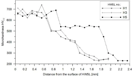
Fig. 16. Generally, the microhardness data indicate that the size of eutectic carbides has a direct impact on the overall hardness of the HWSL. Note that the average hardness values for the hypo-eutectic HWSLs no. H1 and no. H3, that is with the eutectic regions composed of γe + M3C and γe + M7C3, respectively,
are similar. In the above-mentioned cases, the average hardness was approx. 673 HV and 677 HV, respectively. In contrast, it is well known that M7C3
carbides are significantly harder than M3C carbides
(hardness ranges of M3C and M7C3 are 1060 HV
to 1230 HV and 1500 HV to 1800 HV, respectively
[16]). Additionally, the volume fraction of eutectic
regions in the HWSL no. H3 is significantly higher than in the other one. This finding is associated with changes in the morphology of precipitated eutectic carbides. As mentioned previously, increasing the Cr content produces a progressive reduction in the size of eutectic carbides regardless of their type. This suggestion is supported by the hardness profile of the eutectic HWSL no. H5. The eutectic HWSL, having the smallest precipitations of M7C3 eutectic carbides
and their uniform distributions throughout the alloyed layer, exhibited the lowest average hardness value of about 650 HV. Moreover, it is essential to take into consideration that the presence of martensite can also affect the overall hardness of the HWSLs no. H1 and H5. It should be mentioned that a detailed microstructural analysis of the eutectic regions is currently in progress and the results will be reported elsewhere.
Fig. 16. Microhardness profiles for the HWSLs no. H1, H3, and H5
3 CONCLUSIONS
The hypoeutectic and eutectic HWSLs with a thickness up to 1.1 mm have been obtained on the DCI grade EN-GJS-700-2 substrate by the HPDD laser surface alloying with a pure chromium powder. The composition of the uniformly alloyed
layer contained up to 14.4 wt.% Cr. The type and morphology of eutectic carbides are influenced by both the Cr concentration in the molten pool and solidification conditions. It has been determined that when the total Cr content in the HWSL is higher than 10 wt.% the eutectic regions are composed almost completely of γe + M7C3. In turn, Cr contents higher
than 12 wt.% ensure a formation of the eutectic microstructure (γe + M7C3). In general, the size of the
eutectic carbides is found to decrease with increasing Cr content, regardless of the carbide type. One possible explanation for this finding is that the Cr concentration in the molten pool, at constant heat input level, influences the nucleation and growth process in the eutectic regions. Increasing the Cr content increases the eutectic carbide nucleation limiting their growth. At constant Cr content in the hypo-eutectic HWSL, the fraction of the eutectic carbides increases with a decrease of solidification and cooling rates. This variation in the fraction of eutectic carbides is attributed to a change of the Cr content in the primary austenite grains. Faster solidification and cooling rates result in the higher amount of Cr enrichment in the primary austenite grains, which, in turn, reduces the extent of the eutectic structure.
4 ACKNOWLEDGEMENTS
Publication of this article was funded by statutory grant of the Faculty of Mechanical Engineering, Silesian University of Technology.
5 REFERENCES
[1] Fraś, E., Górny, M., Kapturkiewicz, W. (2013). Thin wall ductile
iron casting: technological aspects. Archives of Foundry Engineering, vol. 13, no. 1, p. 23-28, DOI:10.2478/afe-2013-0005.
[2] Abboud, J.H. (2012). Microstructure and erosion characteristic of nodular cast iron surface modified by tungsten inert gas. Materials and Design, vol. 35, p. 677-684, DOI:10.1016/j. matdes.2011.09.029.
[3] Alabeedi, K.F., Abboud, J.H., Benyounis, K.Y. (2009). Microstructure and erosion resistance enhancement of nodular cast iron by laser melting. Wear, vol. 266, no. 9-10, p. 925-933, DOI:10.1016/j.wear.2008.12.015.
[4] Sun, G., Zhou, R., Li, P., Feng, A., Zhang, Y. (2011). Laser surface alloying of C-B-W-Cr powders on nodular cast iron rolls. Surface and Coatings Technology, vol. 205, no. 8-9, p. 2747-2754, DOI:10.1016/j.surfcoat.2010.10.032.
[5] Tański, T., Pakieła, W., Janicki, D., Tomiczek, B., Król, M.
[6] Sušnik, J., Grum, J., Šturm, R. (2015). Effect of pulse laser energy density on TiC cladding of aluminium substrate.
Tehnički vjesnik - Technical Gazette, vol. 22, no. 6, p.
1553-1560, DOI:10.17559/TV-20150221215735.
[7] Nelson, G.D., Powell, G.L.F., Linton, V.M. (2006). Investigation of the wear resistance of high chromium white irons. Surface Modification Technologies 2005: Proceedings of the 19th International Conference on Surface Modification Technologies, p. 111-118.
[8] Janicki, D. (2017). Laser cladding of Inconel 625-based composite coatings reinforced by porous chromium carbide particles. Optics and Laser Technology, vol. 94, p. 6-14,
DOI:10.1016/j.optlastec.2017.03.007.
[9] Dogan, O.N., Hawk, J.A., Laird II, G. (1997). Solidification structure and abrasion resistance of high chromium white irons. Metallurgical and Materials Transactions A, vol. 28, no. 6, p. 1315-1328, DOI:10.1007/s11661-997-0267-3.
[10] Yan, H., Wang, A., Xiong, Z., Xu, K., Huang, Z. (2010). Microstructure and wear resistance of composite layers on a ductile iron with multicarbide by laser surface alloying. Applied Surface Science, vol. 256, no. 23, p. 7001-7009,
DOI:10.1016/j.apsusc.2010.05.015.
[11] Heydarzadeh Sohi, M., Ebrahimi, M., Ghasemi, H.M.,
Shahripour, A. (2012). Microstructural study of surface melted
and chromium surface alloyed ductile iron. Applied Surface Science, vol. 258, no. 19, p. 7248-7353, DOI:10.1016/j. apsusc.2012.04.014.
[12] Zárubová, N., Kraus, V., Čermák, J. (1992). Mechanisms of
phase transformations during laser treatment of grey cast iron. Journal of Materials Science, vol. 27, no. 13, p. 3487-3496, DOI:10.1007/BF01151824.
[13] Janicki, D. (2015). Direct diode laser surface melting of nodular cast iron. Applied Mechanics and Materials, vol. 809-810, p. 423-428, DOI:10.4028/www.scientific.net/AMM.809-810.423.
[14] Voigt, R.C., Lopper, C.R. (1983). A study of heat-affected zone
structure in ductile cast iron. Welding Journal, vol. 62, p. 82-88.
[15] Orłowicz, W., Trytek, A. (2007). Shaping the microstructure and
surface properties of ductile cast iron components by means of plasma surface modification. Archive of Foundry, vol. 7, no. 23. (in Polish)
[16] Song, L. Qiao, Y., Wang, M. (2013). Effect of carbide orientation on inpact-abrasive wear resistance of high-Cr iron used in shot balast machine. Tribology Letters, vol. 50, no. 3, p. 439-448,