0 INTRODUCTION
Small, claw-poled, permanent-magnet (PM), stepper motors [1] to [3] are commonly used in many home appliances, industrial applications and the automotive industry due to their positioning abilities and their relatively low cost. The performance of the motor is defined by the materials used and its geometrical details, particularly the stator poles. However, optimizing the geometry in order to achieve a higher torque can sometimes affect the stepping accuracy and the dynamics of the rotor’s movement.
Optimization of the driving torque and minimization of the detent torque are common tasks in the development of prototype steppers; therefore, many published patents and investigations can be found that relate to these topics [4] to [6]. An informative investigation was published in 2006 by Liu et al. [5], where a study of different ratios of teeth bases and different teeth heights was made. Because of the constant tooth surface used in the analysis, the holding and detent peak torques presented are very informative. Another study by Liu et al.[6]was carried out to investigate the influence of the stator stack gap. The experiment showed improved stepping when the gap was increased.
In order to obtain a clearer insight into the influence of multiple geometrical parameters on the driving torque, detent torque and stepping accuracy, an extensive study is presented in this paper, using
the full-scale 3-D FEM and a custom code for the stepping simulation. The results are organized to help engineers quickly find the most influential parameters to optimize their motors. Such information can prove itself highly useful in industry where short deadlines and high investments do not allow for a time-consuming research, simulations, prototype manufacturing and testing.
1 PROTOTYPE MOTOR
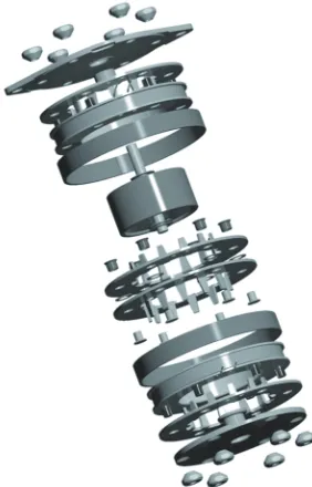
To ensure that the effects of the investigated parameters are as “isolated” as possible, a new construction was employed for the stator. This modular concept also allows the simple manufacturing of parts, assembly and disassembly of the motor (Figs. 1 and 2). This is very important, because it saves valuable resources, while only four parts have to be changed in the assembly when investigating pole-shape design and stator-rotor air gap. Because only the poles, stator rings and permanent magnets are made of magnetic material, the geometry of the motor is very simple/ basic. The minimum necessary “errors” in the stator are, therefore, six symmetric circular-pattern holes for mounting/positioning and two small holes for the winding leads. Manufacturing and assembly errors [7] that always occur in real life can be easily tested by replacing the stack-separating washers or changing the position or the shape of the six positioning holes.
Parametric Study of a Permanent-Magnet Stepper
Motor’s Stepping Accuracy Potential
Škofic, J. – Koblar, D. – Boltežar, M. Jan Škofic1 – David Koblar2 – Miha Boltežar3,*
1 Iskra-Mehanizmi, Slovenia 2 Domel, Slovenia
3 University of Ljubljana, Faculty of Mechanical Engineering, Slovenia
This paper deals with a large-scale parametric study of geometrical influences on the stepping accuracy of a small, claw-poled, permanent-magnet stepper motor. Even though the main focus is on the claw-poles, other parameters, such as the permanent-permanent-magnet height and the stack air gap, are varied in order to obtain a complete insight into the importance of the individual details. Compactly presented results can help engineers considerably lower the times needed to find the optimum design for the developed motor.
Keywords: stepper motors, permanent-magnet motors, finite-element methods, magnetostatics, torque, movement simulation
Highlights
• Proposed modular construction of the motor. • Large-scale parametric study.
• Altered geometry PM (permanent-magnet) modeling approach.
Fig. 1. Modular PM stepper motor
Fig. 3 and Table 1 present the parameters and their values that are investigated in this paper. The tooth base width (PA) is defined by an angle, whereas all the other parameters, such as tooth height (H), vertical chamfer (VC), horizontal chamfer (HC), stack separation (S) and permanent-magnet height (MH), are defined in millimeters. The analysis is designed to have one main version/prototype (V01) with PA = 15°, H = 5 mm, VC = 3 mm, HC = 1 mm, S = 0.2 mm, MH = 12 mm, from which all other versions derive. For example, version V02 is identical to V01, with the exception of the tooth-width parameter, which changes to PA = 14°. We decided to use this approach in order to emphasize the effect of the parameter when optimizing a base prototype. The parameters are kept well within the feasible manufacturing range.
Fig. 2. Exploded view of the motor
The low-cost, bipolar, claw-poled, PM, stepper motor investigated in this work (Fig. 2) has 48 poles, corresponding to a 7.5° step angle. In each of the
two phases of the stator, a 0.35mm copper-alloy wire is used for a winding with 160 turns. The stator is formed from cold-rolled, low-carbon strip steel with an inner diameter of 23 mm and an outer diameter of 42 mm. The motor is designed to be driven with 0.8 A and ~12 V.
Fig. 3. Investigated parameters
Table 1: Investigated parameters
PA [°] / / 15 V01 14 V02 13 V03 12 V04
H [mm] 4.4 V05 4.7 V06 5 5.3 V07 5.6 V08 /
VC [mm] / 2.5 V09 3 3.5 V10 4 V11 /
HC [mm] 0.7 V12 0.85 V13 1 1.15 V14 1.3 V15 /
S [mm] / 0.1 V16 0.2 0.3 V17 0.4 V18 /
MH [mm] / / 12 12.8 V19 13.6 V20 14.4 V21
2 THEORETICAL BACKGROUND
2.1 FEM Calculation Details
Fig. 4. Magnetic flux density profile of a PM; a) typical segment approach, b) alternative geometrical approach, c) measured average magnetic flux density at approximately 0.15 mm away
from the magnet surface
Since a low-cost motor is being analyzed here, the PM rotor creates a specific challenge. An Nd-Fe-Co-B magnetic powder was mixed with a temperature-stable epoxy resin and pressed into a mold to form an economical, effective and magnet [14]. However, at this stage the magnet is yet to be magnetized in the magnetizing machine to create the radially magnetized segments. Because there is a considerable amount of resin, air pockets and optionally fibers in the magnet, the energy product, residual induction and coercive force all change respectively to volumetric loading of the magnetic powder (specified by the manufacturer). The magnetized magnet also has a sinusoidal magnetic flux distribution along its tangential direction (Fig. 4c), which is in slight conflict with the result of the simulation if a simple radial segments of the PM ring are used (Fig. 4a). Due to these problems with the need of scaling the magnetic material properties and obtaining sinusoidal shaped magnetic density profile (Fig. 4c) a simple method for changing the geometry of the PM was developed [15]. The segment’s geometry and volume are changed to suit the volume portion of the magnetic material and also the inner and outer PM diameters. Such a model therefore keeps the original diameters, the thickness of the wall and the very important rotor-stator air gap [16]. The shape of the elements is not explicitly defined due to the variation of the volumetric loading of magnetic powder and angular width of the segment. For the first approximation the sine shape can be used. Typically less than 4 iterations are needed to obtain the satisfactory shape that corresponds to desired volume. The magnetic flux density of the elliptically
shaped segments (Fig. 4b) resembles the sinusoidal distribution more closely than the typical approach (Fig. 4a).
Using the FEM we calculated five torque-displacement curves: the detent and four driving curves. These driving torque-displacement curves are defined by the driving current energizing only one phase of the motor ([I1 = 0.8 A, I2 = 0 A] = c16,
[I1 = 0 A, I2 = 0.8 A] = c32, [I1 = –0.8 A, I2 = 0 A] = c48,
[I1 = 0 A, I2 = –0.8 A] = c64). The reconstruction of
the other curves represented in any stepping mode can be made using Eq. (1) to (4), where c16, c32, c48 and c64 are the calculated primary torque vectors, cX
is the reconstructed torque vector, n is the nth vector
element, I1 is the current in the first phase and I2 is the
current in the second phase.
For 0 A < I1 < 0.8 A and –0.8 A < I2 < 0 A: cX n
( )
=c64( )
n I cX⋅ 2( )
+c16( )
n I cX⋅ 1( )
. (1)For 0.8 A > I1 > 0 A and 0 A < I2 < 0.8 A: cX n
( )
=c16( )
n I cX⋅ 1( )
+c32( )
n I cX⋅ 2( )
. (2)For 0 A > I1 > –0.8 A and 0.8 A > I2 > 0 A: cX n
( )
=c32( )
n I cX⋅ 2( )
+c48( )
n I cX⋅ 1( )
. (3)For –0.8 A < I1 < 0 A and 0 A > I2 > –0.8 A: cX n
( )
=c48( )
n I cX⋅ 1( )
+c64( )
n I cX⋅ 2( )
. (4)The reconstruction of all the torque-displacement curves for the desired stepping mode is fast and simple, but also very informative. Any small errors in the primary torque-displacement curves can have a significant effect on others that have not been calculated with the FEM, resulting in a compromised stepping accuracy.
The primary curves were computed with FEM and the use of B-H curve for the metal, so they include the detent torque and saturation effects. Because the reconstruction expressions (Eq. (1) to (4)) produce torque curves that are only a linear combination of the primary ones, we can expect some minor discrepancies compared to a FEM calculated curves.
2.2 Stepping Simulation
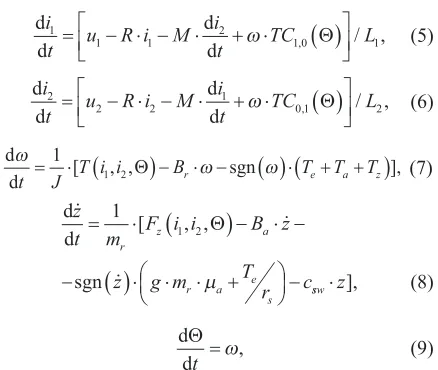
The stepping simulation was performed with the help of a developed system of equations [15] that uses torque-displacement curves and the force-displacement curves obtained, as described in section 2.1, to simulate both the rotational and axial [17] movements of the rotor. Once the FEM results for torque-displacement and force-displacement curves are obtained and stored, any movement simulation can be quickly calculated using Eq. (5) to (9):
d d
d d i
t1 = u R i M i1− ⋅ −1 ⋅ t2 + ⋅TC1 0
( )
L1
ω , Θ / , (5) d
d
d d i
t2 = u2− ⋅ −R i M i2 ⋅ t1+ ⋅TC0 1
( )
L2
ω , Θ / , (6) d
d
ω
ω ω
t = ⋅1J [T i i
(
1 2, ,Θ)
−Br⋅ −sgn( )
⋅(
T T Te+ +a z)
], (7) d d zt m F i i B z
z g m T r c
r z a
r a e
s = ⋅
(
)
− ⋅ − −( )
⋅ ⋅ ⋅ + − 1 1 2 [ , , sgn Θµ ssw⋅z], (8) d
d
Θ
t =ω, (9)
where i1, i2 are the currents in both phases, u1, u2
are the voltages, R is the winding resistance, L is the winding inductance, J is the rotor inertia, Br
is the rotational movement damping constant, Ba
is the axial movement damping constant, M is the
mutual inductance of the windings, TC1,0 (θ) is the
torque curve calculated with the FEM, when only one winding is fully energized (note that it must be calculated with 1 A winding current or normalized to 1 A to satisfy unit requirements), T(i1,i2,θ) is the
torque defined by Eq. (1) to (4) for the current rotor position, Te is the friction torque generated by the rotor’s eccentricity, Ta is the extra friction torque added to the motor (gearbox, encoder, etc.), Tz is the friction torque caused by the rotor’s axial movement Eq. (10), z is the rotor’s axial velocity, mr is the mass
of the rotor, Fz(i1,i2,θ) is the axial force for the current
rotor position (defined in a similar way to the torque
T(I1,I2,θ)), g is the acceleration due to gravity (in
current application the motor’s axis lays in horizontal plane), μr is the coefficient of friction between the
plain brass bearing and the stainless-steel shaft,
csw is the spring-washer constant, and z is the axial
displacement of the rotor.
Spring washers, located between rotor and plain bearings (Fig. 2), help to maintain the axial position of
the rotor, and so contribute to the good vibro-acoustic aspects of the product. The axial movement of the rotor, governed by Eq. (8), causes the compression of either the upper or lower spring washer. Compression creates a friction torque TZ that affects the rotation. In
Eq. (10) rbf represents the mean radius of the bearing
flange and μa is the axial friction coefficient.
TZ=c z rsw⋅ ⋅ ⋅bf µa, (10) T m re= r⋅ ⋅e ω µ2⋅ r⋅rs. (11) The friction torque caused by the mass eccentricity of the rotor Te is described by Eq. (11), where re is
the eccentricity and rs is the shaft radius. The mass
eccentricity should not be confused with geometrical run-out of the rotor. The run-out would affect the magnetic field and change the FEM calculated torque-displacement and force-displacement curves [18], [19]. For the motors constructed without spring washers, Eq. (8) should be altered to incorporate the effects of a collision between the rotor and the bearings.
3 MODEL VALIDATION
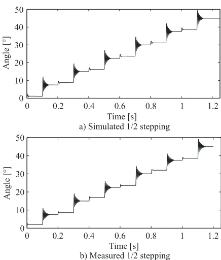
In order to validate the proposed simulation method, a simple experiment allowing the measurement of the rotational displacement of the shaft was made [15]. The shaft of the motor was coupled with a Scancon miniature encoder using 10-7 kgm2 of inertia and 0.5
Nmm of friction torque. The encoder has a resolution of 7500 lines per rotation, which is then multiplied by four in the measuring software. The data acquisition was performed with a 20 kHz sampling frequency. The motor was driven with an AMIS-30623, bipolar, stepper-motor chip based on LIN communication (automotive CAN standard sub frame).
stepping abilities. The schematics of experimental setup, additional measurements and model validation is available in previous work [15].
0 0.2 0.4 0.6 0.8 1 1.2
0 10 20 30 40 50
T
a) Simulated 1/2 stepping ime [s]
Angle [°]
0 0.2 0.4 0.6 0.8 1 1.2
0 10 20 30 40 50
Angle [°]
Time [s] b) Measured 1/2 stepping
Fig. 5. a) simulation and b) measurement comparison of the ½-stepping
4 SIMULATION RESULTS
4.1 FEM Calculated Torque Properties
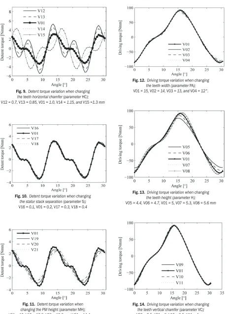
An investigation of the FEM calculated torque-displacement curves not only lets us characterize the peak detent and driving torque, but also the zero-crossings and zero-crossing gradients. The gradient defines the motor’s ability to secure the step position. A steep curve is important in applications where a high operating friction is expected, because the positioning will be much more accurate. The gradient also affects the oscillating frequency of the rotor. The shape of the curve will affect the rotor’s high-speed rotational movement, because a high torque ripple causes the rotor to run more roughly. Figs. 6 to 11 are showing the detent torque-displacement curves for each prototype. Each individual figure represents the effect of the variation of only one parameter. Because prototype V01 is the base motor, its data is shown in all the figures. The situation is similar for Figs. 12 to 17, where the plotted driving torque curves were calculated with I1 = 0.8 A and I2 = 0 A.
Fig. 6. Detent torque variation when changing the teeth width (parameter PA); V01 = 15, V02 = 14, V03 = 13, and V04 = 12°
Fig. 7. Detent torque variation when changing the teeth height (parameter H);
V05 = 4.4 , V06 = 4.7 , V01 = , V07 = 5, and V08 = 5.6 mm
Fig. 8. Detent torque variation when changing the teeth vertical chamfer (parameter VC);
Fig. 9. Detent torque variation when changing the teeth horizontal chamfer (parameter HC);
V12 = 0.7, V13 = 0.85, V01 = 1.0, V14 = 1.15, and V15 =1.3 mm
Fig. 10. Detent torque variation when changing the stator stack separation (parameter S);
V16 = 0.1, V01 = 0.2, V17 = 0.3, V18 = 0.4
Fig. 11. Detent torque variation when changing the PM height (parameter MH);
V01 = 12, V19 = 12.8, V20 = 13.6, and V21 = 14.4 mm
Fig. 12. Driving torque variation when changing the teeth width (parameter PA);
V01 = 15, V02 = 14, V03 = 13, and V04 = 12°.
Fig. 13. Driving torque variation when changing the teeth height (parameter H);
V05 = 4.4, V06 = 4.7, V01 = 5, V07 = 5.3, V08 = 5.6 mm
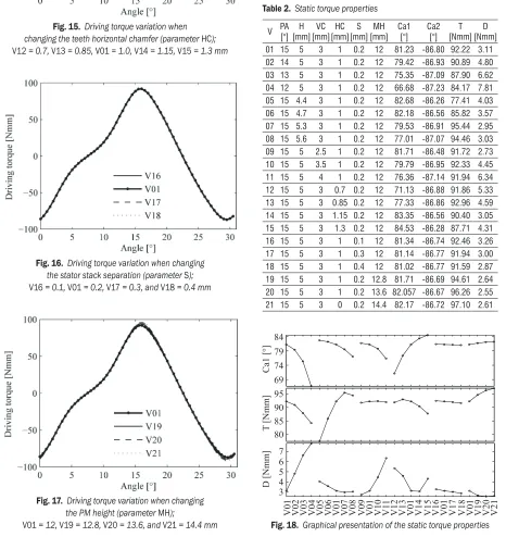
Fig. 15. Driving torque variation when changing the teeth horizontal chamfer (parameter HC);
V12 = 0.7, V13 = 0.85, V01 = 1.0, V14 = 1.15, V15 = 1.3 mm
Fig. 16. Driving torque variation when changing the stator stack separation (parameter S);
V16 = 0.1, V01 = 0.2, V17 = 0.3, and V18 = 0.4 mm
Fig. 17. Driving torque variation when changing the PM height (parameter MH);
V01 = 12, V19 = 12.8, V20 = 13.6, and V21 = 14.4 mm
According to the data in Figs. 6 to 17 the most influential parameter is the tooth base width (Fig. 6), for the detent characteristics, and the tooth height (Fig. 13), for the driving torque characteristics. Naturally, the peak driving torque has a lot to do with the change of the surface area of the teeth. Interestingly, the vertical chamfer has a major influence on the detent (Fig. 8), but much less influence on the driving torque (Fig. 14). Increasing the permanent-magnet height (MH) seems to have a positive effect on lowering the detent and increasing the peak driving torque.
Table 2. Static torque properties
V PA [°][mm]H [mm]VC [mm]HC [mm]S [mm]MH Ca1 [°] Ca2 [°] [Nmm]T [Nmm]D
01 15 5 3 1 0.2 12 81.23 -86.80 92.22 3.11
02 14 5 3 1 0.2 12 79.42 -86.93 90.89 4.80
03 13 5 3 1 0.2 12 75.35 -87.09 87.90 6.62
04 12 5 3 1 0.2 12 66.68 -87.23 84.17 7.81
05 15 4.4 3 1 0.2 12 82.68 -86.26 77.41 4.03
06 15 4.7 3 1 0.2 12 82.18 -86.56 85.82 3.57
07 15 5.3 3 1 0.2 12 79.53 -86.91 95.44 2.95
08 15 5.6 3 1 0.2 12 77.01 -87.07 94.46 3.03
09 15 5 2.5 1 0.2 12 81.71 -86.48 91.72 2.73
10 15 5 3.5 1 0.2 12 79.79 -86.95 92.33 4.45
11 15 5 4 1 0.2 12 76.36 -87.14 91.94 6.34
12 15 5 3 0.7 0.2 12 71.13 -86.88 91.86 5.33
13 15 5 3 0.85 0.2 12 77.33 -86.86 92.96 4.59
14 15 5 3 1.15 0.2 12 83.35 -86.56 90.40 3.05
15 15 5 3 1.3 0.2 12 84.53 -86.28 87.71 4.31
16 15 5 3 1 0.1 12 81.34 -86.74 92.46 3.26
17 15 5 3 1 0.3 12 81.14 -86.77 91.94 3.00
18 15 5 3 1 0.4 12 81.02 -86.77 91.59 2.87
19 15 5 3 1 0.2 12.8 81.71 -86.69 94.61 2.64
20 15 5 3 1 0.2 13.6 82.057 -86.67 96.26 2.55
21 15 5 3 0 0.2 14.4 82.17 -86.72 97.10 2.61
The results are summarized in Table 2 and visually in Fig. 18, where Ca1 is the angle of torque-displacement zero-crossing on the left of the peak, Ca2 is the angle of the torque-displacement zero-crossing on the right of the peak, the T peak driving torque and the D peak detent torque.
4.2 Stepping Simulation Results
The simulation of the stepping was carried out by considering a real test setup, where the shaft of the motor is coupled with a miniature encoder. Therefore, the added inertia and friction of the encoder and the coupling errors are included in the simulation parameters. Every version of the motor was tested in five different regimes (1/1, 1/2, 1/4, 1/8, 1/16 stepping), where the virtual driver directed 18 consecutive steps every tenth of a second (allowing the rotor to settle down after each step) with V = 12 V
and Irun = 0.8 A. The steps were then analyzed and
presented in the form of a statistical range (SR), which is the difference between the maximum and minimum step in each stepping mode. The theoretical step size in the 1/1 stepping mode is 7.5°, in the 1/2 mode it is 3.75°, in the 1/4, 1.875°, and so on.
Table 3. Step angle statistical range
V SR 1/1 [°] SR 1/2 [°] SR 1/4 [°] SR 1/8 [°] SR 1/16 [°]
01 0.306 0.525 1.971 1.537 0.966
02 0.292 0.599 2.233 2.012 1.191
03 0.254 1.307 2.573 2.066 1.513
04 0.266 0.938 2.576 2.818 1.752
05 0.495 0.594 1.640 1.209 0.676
06 0.385 0.428 1.749 1.330 0.803
07 0.373 0.533 2.202 1.836 1.180
08 0.351 1.346 2.436 1.947 1.238
09 0.403 0.675 1.781 1.493 0.850
10 0.278 0.485 2.347 1.912 1.177
11 0.359 0.629 2.265 1.980 1.453
12 0.271 1.436 2.435 2.367 1.421
13 0.274 0.820 2.344 1.874 1.294
14 0.448 0.466 1.435 1.145 0.610
15 0.317 0.546 1.070 0.834 0.377
16 0.319 0.452 1.934 1.481 0.912
17 0.331 0.614 2.045 1.587 0.963
18 0.318 0.635 2.078 1.615 0.997
19 0.288 0.589 1.919 1.502 0.954
20 0.309 0.568 1.823 1.463 0.924
21 0.305 0.496 1.812 1.438 0.882
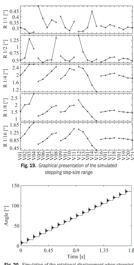
Table 3 and Fig. 19 should, in theory, present the smallest step-size range for the prototypes with the
most sine-like driving torque-displacement curves. Every deviation from ideal sine should be reflected in distorted reconstructed curves that define the static stepping potential. If we follow the individual parameter vertically (from 1/1 to 1/16 mode) in Fig. 19, the theory is confirmed as the prototype V15 with the smallest difference between Ca1 and Ca2 (and therefore the least-distorted torque-displacement curve) proves to be the most accurate motor in micro-stepping positioning.
0.3 0.35 0.4 0.45
R 1/1 [°]
V01 V02 V03 V04 V05 V06 V01 V07 V08 V09 V01 V10 V1
1
V12 V13 V01 V14 V15 V16 V01 V17 V18 V01 V19 V20 V21
0.5 0.75 1 1.25
R 1/2 [°]
1.2 1.6 2 2.4
R 1/4 [°]
1 1.5 2 2.5
R 1/8 [°]
0.45 0.85 1.25 1.65
R 1/16 [°]
Fig. 19. Graphical presentation of the simulated stepping step-size range
Fig. 20. Simulation of the rotational displacement when stepping a V04 in the full-stepping mode.
of the stepping in the full-stepping mode for the V04 motor. Full stepping is normally not problematic for low-cost steppers. The accuracy is, in most cases and applications, satisfactory.
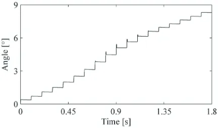
The problems occur when driving the motor in micro-stepping modes. The steps can deviate considerably from the theoretical ones. The V04 motor is the most inaccurate motor in 1/16 stepping (unequal steps). The rotational displacement is shown in Fig. 21.
Fig. 21. Simulation of rotational displacement when stepping a V04 in the 1/16 stepping mode.
The difference between the stepping accuracy of the least accurate (V04) and the most accurate (V15) can be seen by comparing Figs. 21 and 22. The steps of V15 motor are in comparison with V04 much more consistent (equal displacements), which is important for precise and repeatable positioning.
Fig. 22. Simulation of the rotational displacement when stepping a V15 in the 1/16 stepping mode
5 CONCLUSIONS
In this paper we present the effects of motor geometry details on the stepping-accuracy potential for over 20 different prototypes simulated with an experimentally validated numerical model. The investigated parameters were varied around a base prototype in order to give the reader exact information about the effect of the applied change. This analysis
also shows that some compromises have to be made when designing a low-cost PM stepper, because the strongest motor might not be the most accurate in a particular operation. The strongest motor was found to be V21 with the highest permanent magnet, and the most accurate the V15 with increased vertical chamfer.
Note that the parameters investigated in this work are not the only means of manipulating the detent and driving torque. Making some de-symmetrization [20] on the stator teeth or altered magnetization [21], [22] of the PM are patented and sometimes effective methods. More information about the optimization of the PM machines can be found in [2].
6 ACKNOWLEDGMENT
With special thanks to prof. Janez Diaci, University of Ljubljana, Faculty of Mechanical Engineering. Operation is partly financed by the European Union, European Social Fund.
7 REFERENCES
[1] Acarnley, P. (2007). Stepping Motors: A Guide to Theory and Practice, 4th ed. IET, London, DOI:10.1049/ PBCE063E.
[2] Gieras, J.F. (2010). Permanent Magnet Motor
Technology: Design and Applications, 3rd ed. CRC
Press, Boca Raton.
[3] Bianculli, A.J. (1970). Stepper motors: Application and selection. IEEE Spectrum, vol. 7, no. 12, p. 25-29, DOI:10.1109/MSPEC.1970.5213082.
[4] Jung, D. S., Lim, S.B., Kim, K.C., Ahn, J.S., Go, S.C., Son, Y.G., Lee, J. (2007). Optimization for improving static torque characteristic in permanent magnet stepping motor with claw poles. IEEE Transanctions on Magnetics, vol. 43, no. 4, p. 1577-1580, DOI:10.1109/ TMAG.2006.892102.
[5] Liu, C.P., Li, Y.C., Liu, K.H., Wu, K.T., Yao, Y.D. (2006). Analysis of the performance of permanent magnetic stepping motor with trapezoid stator tooth.
Journal of Applied Physics, vol. 99, no. 8, p. 08R316-08R316-3, DOI:10.1063/1.2167637.
[6] Liu, C.P., Jeng, G.R., Chen, W.C., Tsai, M.C., Wu, K.T., Yao, Y.D. (2007). Performance of claw-poled pm-stepping motor. Journal of Magnetism and Magnetic Materials, vol. 310, no. 2, p. e910-e912, DOI:10.1016/j. jmmm.2006.10.945.
[7] Coenen, I., van der Giet, M., Hameyer, K. (2012). Manufacturing tolerances: Estimation and prediction of cogging torque influenced by magnetization faults.
IEEE Transactions on Magnetics, vol. 48, no. 5, p.
1932-1936, DOI:10.1109/TMAG.2011.2178252. [8] Ahn, J.H., Park, S.C., Rhyu, S.H., Jung, I.S. (2005).
motor. Proceedings 8th International Conference on
Electrical Machines and Systems, Nanjing, p. 276-279, DOI: 10.1109/ICEMS.2005.202529.
[9] Ishikawa, T., Takakusagi, R., Matsunami, M. (2000). Static torque characteristics of permanent magnet type stepping motor with claw poles. IEEE Transactions
on Magnetics, vol. 36, no. 4, p. 1854-1857,
DOI:10.1109/20.877806.
[10] Rhyu, S.H., Kwon, B.I. (2006). Newly structured micro permanent magnet type stepping motor with claw-poles. IEEE Transactions on Magnetics, vol. 42, no. 4, p. 1331-1334, DOI:10.1109/TMAG.2006.872482. [11] Bayat, F., Fadaie Tehrani, A., Danesh, M. (2012).
Finite element analysis of proportional solenoid characteristics in hydraulic valves. International Journal of Automotive Technology, vol. 13, no. 5, p. 809-816, DOI:10.1007/s12239-012-0081-9.
[12] Rossini, L., Chetelat, O., Onillon, E., Perriard, Y. (2013). Force and torque analytical models of a reaction sphere actuator based on spherical harmonic rotation and decomposition. IEEE/ASME Transactions
on Mechatronics, vol. 18, no. 3, p. 1006-1018,
DOI:10.1109/TMECH.2012.2195501.
[13] Okada, Y., Kawase, Y., Hisamatsu, Y. (2003). Analysis of claw-poled permanent magnet-stepping motor considering deterioration of material characteristics by remains stress. IEEE Transactions on Magnetics, vol. 39, no. 3, p. 1721-1724, DOI:10.1109/ TMAG.2003.810347.
[14] Haavisto, M., Kankaanpää, H., Paju, M. (2011). Estimation of time-dependent polarization losses in sintered nd-fe-b permanent magnets. IEEE Transactions on Magnetics, vol. 47, no. 1, p. 170-174, DOI:10.1109/TMAG.2010.2089692.
[15] Škofic, J., Boltežar, M. (2014). Numerical modeling
of the rotor movement in a permanent-magnet stepper motor. IET Electric Power Applications, E-First Articles, DOI:10.1049/iet-epa.2013.0274.
[16] Kadota, Y., Inoue, K., Uzuka, K., Suenaga, H., Morita, T. (2013). Noncontact operation of a miniature cycloid motor by magnetic force. IEEE/ASME Transactions
on Mechatronics, vol. 18, no. 5, p. 1563-1571,
DOI:10.1109/TMECH.2012.2208225.
[17] Nguyen, Q.D., Ueno, S. (2011). Modeling and control of salient-pole permanent magnet axial-gap self-bearing motor. IEEE/ASME Transactions on Mechatronics, vol. 16, no. 3, p. 518-526, DOI:10.1109/ TMECH.2010.2045392.
[18] Hsieh, M.F., Yeh, Y.H. (2013 ). Rotor eccentricity effect on cogging torque of pm generators for small wind turbines. IEEE Transactions on Magnetics, vol. 49, no. 5, p. 1897-1900, DOI:10.1109/TMAG.2012.2237021. [19] Zhu, Z., Wu, L., Mohd Jamil, M. (2013). Distortion
of back-emf and torque of pm brushless machines due to eccentricity. IEEE Transactions on Magnetics, vol. 49, no. 8, p. 4927 – 4936, DOI:10.1109/ TMAG.2013.2246181.
[20] Wang, D., Wang, X., Qiao, D., Pei, Y., Jung, S.-J. (2011). Reducing cogging torque in surface-mounted permanent-magnet motors by nonuniformly distributed teeth method. IEEE Transactions on Magnetics, vol. 47, no. 9, p. 2231-2239, DOI:10.1109/ TMAG.2011.2144612.
[21] Lim, S. B., Jung, D.S., Kim, K.C., Koo, D.H., Lee, J. (2007). Characteristic analysis of permanent-magnet-type stepping motor with claw poles by using 3 dimensional finite element method. IEEE
Transactions on Magnetics, vol. 43, no. 6, p.
2519-2521, DOI:10.1109/TMAG.2007.893999.
[22] Hattori, T., Suzuki, Y., Yamada, T. (2008). Analysis of permanent magnet type stepping motor with claw poles using electromagnetic field analysis. International
Conference on Electrical Machines and Systems,