SENSITIVITY DEGRADATION AND ANTENNA ISOLATION ANALYSES
FOR A MULTI-OPERATOR GLOBAL SYSTEMS FOR MOBILE
COMMUNICATION BASE TRANSCEIVER STATIONS
F. O. Ehiagwina
1,*, A. S. Afolabi
2, N. T. Surajudeen-Bakinde
3and O. A. Fakolujo
4 1, DEPARTMENT OF ELECTRICAL AND ELECTRONIC ENGINEERING,THE FEDERAL POLYTECHNIC OFFA,KWARA STATE,NIGERIA2,3,DEPARTMENT OF ELECTRICAL AND ELECTRONIC ENGINEERING,UNIVERSITY OF ILORIN,ILORIN,KWARA STATE NIGERIA 4,DEPARTMENT OF ELECTRICAL AND ELECTRONIC ENGINEERING,UNIVERSITY OF IBADAN,IBADAN,OYO STATE,NIGERIA
E-mail addresses: 1 [email protected], 2 [email protected],
3 [email protected], 4 [email protected]
ABSTRACT
In other to mitigate challenges associated with the expansion of Global System for Mobile Communication (GSM) systems, infrastructure sharing have been proposed and adopted by some GSM operators. When infrastructure sharing is done, there is the possibility of degradation of quality of service due to Electromagnetic Compatibility issues, interference between operators, sensitivity degradation, increasing noise floor, antenna isolation requirement issue. This paper analyses the sensitivity degradation and the effects of spatial separation on antenna isolation requirement of Base Transceiver Station (BTS) receiver for a multi-operator mobile cellular systems. The data used were extracted from standards of organisation like European Telecommunications Standards Institute (ETSI) standards and others. Antenna dimension were obtained from physical observations of BTS site. By comparison with identified metrics in the standards, we verified that the number of operators that can share infrastructure is limited by the allowable sensitivity degradation. It was noted that an antenna isolation of 70dB can be achieved for GSM 900 band antennas and when GSM 1800 band antennas are used, 90dB antenna isolation is achievable greater than the minimum recommendation of 30dB.
Keywords: Antenna isolation, base station, BTS, GSM, infrastructure sharing, receiver sensitivity, sensitivity degradation
1. INTRODUCTION
In spite of the progress made in the development of faster mobile wireless system, the Global System of Mobile communication (GSM) system still accounts for about 50% of subscribers [1]. In the meantime, the high cost of GSM roll-out and high operating coupled with other concerns like proliferation of towers in the urban environment, universal mobile coverage especially among rural dweller have necessitate infrastructure sharing. Infrastructure sharing have been proposed as a viable solution to lower the cost required to roll-out a base station in several countries such as Nigeria [2], [3], Kenya [4], [5], Zimbabwe [6] and across the globe [7]. There
are however, complex challenges associated with GSM infrastructure sharing.
Such complexity involves handling electromagnetic compatibility issues, increased interference level, tower wind loading, degradation of sensitivity and noise floor increase have to be monitored. For instance, in other to manage the Quality of Service (QoS), the sensitivity degradation must not be lower than 3 dB [8]. Additional challenges include policy and regulation related issues, required substantial alignment and parameter tuning, sensitivity and antenna isolation requirement issues [9]–[11]. In [4], Namisiko et al. examined policy and regulation related issues with respect to open ICT infrastructure
Vol. 38, No. 1, January 2019, pp. 177 – 184 Copyright© Faculty of Engineering, University of Nigeria, Nsukka,
Print ISSN: 0331-8443, Electronic ISSN: 2467-8821
www.nijotech.com
sharing by telecom operators in Kenya, Africa. This work was subjective, and did not go into the technicalities of telecom infrastructure. In addition, in our previous work [11], we evaluated wind loading for multi-operators’ GSM tower. Sensitivity degradation and antenna isolation have not be evaluated fully for a multi-operator mobile cellular system.
The focus of this paper is to investigate the effect of sensitivity degradation and antenna isolation of multi-operator Base Transceiver Station (BTS). The sensitivity degradation associated with a single operator BTS is used to deduce a model for evaluating the sensitivity degradation of a multi-operator BTS both for the GSM 900 and GSM 1800 antennas. In addition, the antenna isolation required for increasing number of mobile operators is evaluated.
The rest of this paper is sectioned as follows. In section 2, description of key concepts and works related to sensitivity degradation and antenna isolation are reported. Section 3 presents the mathematical expressions and steps followed in the analyses of sensitivity degradation and antenna isolation of a multi-operator cellular system. The result obtained and the conclusions reached are reported in sections 4 and 5.
2. REVIEW OF KEY CONCEPTS AND RELATED WORKS
In this section of the paper, key concepts and related works in cellular system sensitivity are described to provide context for the presentation that follow. The GSM standards define radio communications systems that work properly only if each component part operates within precise limits. Base stations must transmit enough power, with sufficient fidelity to maintain a call of acceptable quality, without interfering with other transmitters using adjacent frequencies. Among the parameters monitored to ensure proper system operation are sensitivity degradation and antenna isolation requirements.
2.1. Sensitivity Degradation
The presence of other antennas operating in the same frequency band causing degradation, may result in power leaking out of the band causing degradation. Degradation of signal strength, which falls near or lower than the sensitivity of the BTS (around 110dBm) or that of the mobile (around -104dBm) is unacceptable. This is because at this level
of degradation the numbers of call drop increases [12]. Degradation of sensitivity results from the transfer of power from the transmitter to the receiver due to coupling effects.
When sensitivity degradation occurs, it affects the following: the coverage for a set number of users, capacity for a set coverage, and mobile station battery life. It should not exceed 3dB [8].
The sensitivity of a system is a function of fundamental factors such as ambient noise power (NP), carrier-to-noise ratio (C/N) and noise figure (NF). Network operators have no influence on the first two factors. Whereas, NP is a measure of the noise in nature and therefore fixed for the specific carrier bandwidth, C/N is a function of BTS design that measures the relative strength between the received signal and the noise floor.
To improve sensitivity, NF is the target parameter that needs to be enhanced. Noise figure degradation is equivalent to sensitivity degradation [13]. Studies, which examines sensitivity degradation are examine next.
In [14], Khawar et al. studied performance degradation of spectrum sharing scenario involving S-band radar and Long Term Evolution (LTE) cellular system spatially separated. In [15], Boaventura et al. noted that transmitter-to-receiver leakage is capable of degrading sensitivity and performance of passive Radio Frequency Identification (RFID) systems owing to imperfect transmitter-to-receiver isolation, in which a large portion of effective radiation leaks to the receiver.
In this paper, an investigation of sensitivity degradation and antenna isolation requirement of a operator cellular system using models for multi-antenna systems is performed. Parameter extracted from Telecommunication standards such as the International Telecommunication Union, Radio committee (ITU-R) [16] and European Telecommunications Standards Institute (ETSI) [8] were used for comparison and determinants of design constraints.
2.2. Antenna Isolation
presented as follows. Researchers seems to have placed emphasis on developing devices within the radio system to increase antenna isolation, which seems to be more effective in improving isolation. However, the cost of this hardware constitute an increase on the cost of mobile system infrastructure installation.
In [17], Kolodziej et al. developed a radio frequency canceller system, which was inserted at the antenna feeds to enhance the isolation in the presence of reflecting objects at microwave frequencies. This resulted in a 90dB of antenna isolation, when the system coupled with high isolation antenna with omnidirectional properties. In [18], Shrekenhamer and co reported the analytical and experimental design of a high impedance metasurface for use in microwave frequencies antenna isolation. The researchers in [19] developed a two-layer slot-patches one-dimensional electromagnetic band-gap structure, which can be tuned electronically for antenna isolation. The device was used in the common ground plane of two printed monopole antennas in close proximity, so as to minimize mutual coupling between the slot-patches. In [20], Malmstrom and co. evaluated two approaches for estimating the antenna isolation between two vehicle antennas so as to avoid interference between on-board radio systems. The methods evaluated are Non-Singular Transmission Integral (NSTI) and the Geometric Theory of Diffraction (GTD) with significant accuracy obtained by the investigators. The development and use of these additional hardware increases cost of system deployment and may lead to increase insertion losses in the power link budget. Hence, in this work, spatial separation of antennas as a way of enhancing antenna isolation is examined.
3. METHODOLOGY
3.1. Sensitivity Degradation Modelling
System degradation is assessed by the degradation of receiver sensitivity, . It is defined as the receiver
sensitivity degradation due to external interference, and calculated as the noise rise due to the received interference. If represents the received interference and is the victim received noise floor (dBm), then
is as shown in Eqn. (1) [21].
( )
The received noise floor is estimated from the expression given in Eqn. (2) [21]:
Where and are the victim receiver
thermal noise density and noise figure respectively, and BW is receiver noise bandwidth (Hz). And the noise bandwidth is 200,000Hz multiply by the numbers of operators collocating.
3.2. Antenna Isolation Modelling
When an antenna is to be collocated with another, the antenna isolation must be evaluated. The models for antenna isolations (whether horizontal, vertical and slant) are discussed in the following section. It was assumed that isolation is required when antennas of same band (either GSM 900 or GSM 1800) are collocated and that no power leakage occurs between antennas in different bands (GSM 900 and 1800).
a. Horizontal antenna isolation model
When the interferer antenna and the interfered antenna are separated horizontally, then the antenna isolation is given by equation (3) [16].
[ ] ( ⁄ )
⁄
Equation (4) is used to determine electric field effect whether it Near-field, or Fresnel zone or Far-field effect. The parameters involved are defined in Table 1.
Table 1: Antenna Isolation Parameter Parameters Definition
D
the maximum dimension of the largest of the transmitter or receiver antennas in metresH
I
isolation between horizontally separated transmitter and receiver antennas in dBh
d
the horizontal distance from the centre of the interferer antenna to that of the victim receiver antenna in metres
the wavelength of the victim system frequency band in metresTX
Parameters Definition
RX
G
the maximum gain of receiver antenna with respect to an isotropic antenna in dBi
TXSL
the gain of the side-lobe with respect to the main lobe of the transmitter antenna in dB
RXSL
the gain of the side-lobe with respect to the main lobe of the receiver antenna in dBV
I
isolation between vertically separated transmitter and receiver antennas in dBV
d
the vertical distance from the interferer to that of the interfered with receiver antenna, measured from radiation-centre-to-radiation-centre in metresΑ vertical angle between the transmitter antenna and receiver antenna in degrees
S
I
Slant-space antenna isolationb. Vertical antenna isolation model
With the assumption that the vertically separated antennas are perfectly oriented, that is they show pattern nulls to each other. For such a case the antenna isolation is given by equation (5) [16].
[ ] ( ⁄ )
c. Slant-space antenna isolation model
The expression for computing the isolation of antennas separated by slant space is given by equation (6) [16].
[ ] ( ⁄ )
Where and retain their earlier defined meaning. Slant isolation is dependent factors such as the actual shape and taper of the antenna beams. Hence,
[ ] gives an estimation of the actual antenna
isolation value. It must be noted that antenna isolation must not be less than 30dB [22].
3.3. Implementation Procedure
The analysis of the sensitivity degradation and the effects of spatial separation on antenna isolation requirement of BTS receiver for a multi-operator mobile cellular system will involve a proposed five-step procedure, highlighted as follows:
STEP 1: Determine sensitivity and antenna isolation constraints from available standards such as [8, 16, 22].
STEP 2: Determine the expression relating the number of GSM operator to each resource constraint.
STEP 3: Starting from operator, compute sensitivity degradation (eqn. 1), noise floor (eqn. 2), and antenna isolation (eqns. 3-6) of the BTS.
STEP 4: If the results from step 3 are within specified limits, repeat step 3 for -network operators. If not proceed to step 5.
STEP 5: Evaluate antenna-separating distances in order to maintain the specified antenna
isolation at various gain, starting from a low antenna gain value until a gain is reached where antenna isolation requirement can no longer be maintained.
3.4. System Setup
The system is implemented under various scenarios, depending on a specific set of BTS parameters extracted from GSM standard reported in [8], [22], [23]. The hardware used was Hewlett-Packard Compaq Laptop with AMD Sempron (tm) SI-42 2.10GHz processor and 32-bit Window 7 ultimate Operating system. The application used for the implementation was Microsoft Excel 2013. The parameters employed for the analyses are shown in Table 1. Some were obtained from Literatures [8], [22], [23], and physical observations of BTS premises.
Table 1: Implementation Parameters (obtained from [8, 22, 23] and physical site observations)
Parameters Value
Noise figure, (dB) 8.5
Maximum sensitivity degradation,
(dB) 3
Antenna dimension, (m2) 1.0m × 0.3m
Maximum interference level, (dBm) -110 Microwave dish diameter (1), (m) 0.6 Microwave dish diameter (2), (m) 1.2 Thermal noise density at 250C ,
(dBm/Hz) -174
Frequency of the GSM 900 band
antennas, (MHz) 935
Frequency of the GSM 1800 band
antennas, (MHz) 1835
Antenna height, (m) 20-100
Bandwidth of a carrier, (KHz) 200
Number of operators 1-6
4. RESULTS AND DISCUSSION
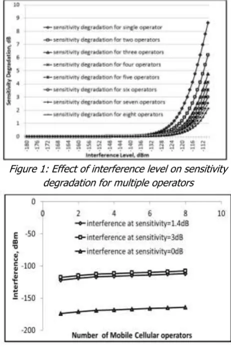
The effect of increasing the numbers of operators on the system performance can be observed in Figure 1. Also observable is the fact that the interference level increases as the numbers of network operator increases. This can be observed by correlating the 3dB sensitivity degradation transition points with the values of interference at which these transitions occur. Figure 2 shows the rise in interference level with an increase in the numbers of GSM network operators. The larger the isolation value the lower the sensitivity degradation and correspondingly, the lower the interference level experienced by the GSM operator. It is observed that after about six (6) operators the sensitivity degradation value becomes lower than 3dB.
The effect of increasing the numbers of GSM network operators on the noise floor of the BTS is shown in Figure 3. It can be observed that as the numbers of operators increase so also the noise floor of the BTS though not linearly. For a noise level not greater than -110dBm, the numbers of GSM operators sharing BTS infrastructure is limited to about six (6). This is similar to the conclusion drawn from the results presented in Figure 1.
The noise floor levels for various numbers of operators were compared with the interference levels at various two levels of sensitivity degradation. Figure 4 shows the comparison at 3dB sensitivity degradation limit, while Figure 5 is a plot of the comparison done at 1.4dB sensitivity degradation limit. Figure 6 is a plot of the comparison done at 0dB sensitivity degradation limit.
It can be observed from Figure 4 that at 3dB the noise floor levels equal the interference level. Therefore, any further increase in sensitivity degradation is not acceptable as that will indicate that the interference level is more than BTS noise floor limit.
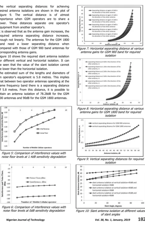
An examination of the effect of antenna gain and antenna separating distance on antenna isolation requirement was done in this part of the paper. The result for this scenario for GSM 900 antennas is shown in Figure 7, while the results for GSM 1800 antennas is shown in Figure 8. Horizontal separating distances for achieving the required antenna isolation determine the minimum distance between two antennas of the same operator. Its value also affects the value of the slant isolation of two antennas slanted to each other.
Figure 1: Effect of interference level on sensitivity degradation for multiple operators
Figure 2: Effect of multiple operators on system interference level
Figure 3: Noise floor variations with the number of operators
The vertical separating distances for achieving desired antenna isolations are shown in the plot of Figure 9. The vertical distance is of utmost importance when GSM operators are to share a tower. These distances separate one operator's equipment from another operator's.
It is observed that as the antenna gain increases, the required antenna separating distance increases, though not linearly. The antennas for the GSM 1800 band need a lower separating distance when compared with those of GSM 900 band antennas for corresponding antenna gains.
Figure 10 shows the required slant antenna isolation for different vertical and horizontal isolation. It can be seen that the value of the slant isolation cannot be lower than the horizontal isolation.
The estimated sum of the lengths and diameters of an operator's equipment is 5.8 metres. This implies that between two operator antennas operating at the same frequency band there is a separating distance of 5.8 metres. From this distance, it is possible to attain an antenna isolation of 78.28dB for the GSM 900 antennas and 90dB for the GSM 1800 antennas.
Figure 5: Comparison of interference values with noise floor levels at 1.4dB sensitivity degradation
Figure 6: Comparison of interference values with noise floor levels at 0dB sensitivity degradation
Figure 7: Horizontal separating distance at various antenna gains for GSM 900 band for required
isolation
Figure 8: Horizontal separating distance at various antenna gains for GSM 1800 band for required
isolation
Figure 9: Vertical separating distances for required isolation
4. CONCLUSIONS
This paper has been able to note that the number of mobile cellular network operator that can effectively share infrastructure on a base station is limited by sensitivity degradation threshold, Interference level, and antenna isolation via a comparison of obtained results with existing standards reported in [8, 16, 23].
From the result, it was observed that theoretically up to six (6) GSM operators can share infrastructure for a passive infrastructure sharing model without severe and unacceptable degradation of system performance. The level of sensitivity degradation must be monitored closely because its value help in determining system performance required to maintain a given interference level and BTS noise floor, which depends on the number of operators antennas collocated in a tower. When the sensitivity degradation is more than 3dB it indicates that the interference level is more than the noise floor limit. From the research, it was observed that an antenna isolation of 70dB can be achieved for GSM 900 band antennas and when GSM 1800 band antennas are used, 90dB antenna isolation is achievable. The recommended antenna isolation is 30dB. The more the antenna isolation the better the system performance will be. Higher antenna isolation leads to a decrease in interference level and intermodulation.
This paper will help radio system designers and mobile network operators when designing collocated or multi-operator cellular systems. Incorporating antenna isolation requirement into the placements of several antennas on a telecommunication tower will enhance the service quality of concerned operators. In this article theoretical analysis was done, however, measurement and analysis in a real life scenario will need to be done and the result compared with the analytical results of this paper.
5 REFERENCES
[1] Chambers, D. “Femtocell Opinion, Comment and Reviews,” Mobile Network Statistics for 2016, 18-Feb-2018. [Online]. Available: https://www.thinksmallcell.com/opinion/mobil e-network-statistics-for-2016.
[2] Ehiagwina, F. O., Fakolujo, O. A., Abdulrahman, Y. A. and Afolabi, L. O. “An Overview of Multi-Operator Global Systems for Mobile Communications Base Stations in the Context of Nigerian Telecommunication
Sector,” Eur. J. Eng. Res. Sci., vol. 1, number 1, pp. 1–6, 2016.
[3] Nosiri, O. C., Agubor, C. K., Akande, A. O. and Ekwueme, E. U. “Telecom Infrastructure Sharing, A Panacea for Sustainability, Cost and Network Performance Optimization in Nigeria Telecom Industry,” Int. J. Sci. Eng. Res., vol. 6, number 8, pp. 621–626, 2015. [4] Namisiko, P., Sakwa, M. and Waweru, M.
“Effects of Network Infrastructure sharing Challenges on Open Information Communication Technology Infrastructure Sharing among Mobile Service Providers in Kenya,” Int. J. Inf. Eng. Electron. Bus., vol. 3, number May, pp. 11–19, 2015.
[5] Charles, M. “ICT Infrastructure Sharing Framework for Mobile Operators in Kenya,” PhD Thesis, University of Nairobi, 2014. [6] Mago, M. and Matekenya, T. “Exploring
Conducive Conditions for Mobile Information Technology Networks Infrastructure Sharing : Case of Zimbabwe,” Imp. J. Interdiscip. Res., vol. 2, number 10, pp. 1796–1809, 2016. [7] Leza, D. “Mobile Infrastructure Sharing:
Trends in Latin America,” in ITU Regional Economic and Financial Forum of Telecommunications/ICTs for Latin America and the Caribbeans, San Jose, Costa Rica, 2014.
[8] European Telecommunications Standard Institute, “Digital Cellular Telecommunications system (Phase 2+); Radio Transmission and Reception,” European Telecommunications Standard Institute, Sophia Antipolis, France, 1996.
[9] Glabowski, M. and Zwierzykowski, P. “Challenges and Constraints in Mobile Network Consolidation Projects,” in Euro Med Telco Conference, Naples, Italy, 2014, pp. 1–5. [10] Kadir, L., Falade, A. J., Abdulrahman, Y. A.
and Mohammed, O. “Tower Sharing and the associated Constraints in Multi-operator GSM Base Transciever Staion,” Int. J. Wirel. Mob. Comput., vol. 11, number 3, pp. 198–206, 2016.
[12] MPT 1378, “Part 1-GSM Base Station Radio Equipment Standard,” Gibraltar Regulatory Authority, United Kingdom, 1999.
[13] Radio Frequency Systems, “TMA Usage in CDMA Networks,” Radio Frequency Systems, 2013.
[14] Khawar, A., Abdel-Hadi, A. and Clancy, T. C. “Spectrum Sharing between S-band Radar and LTE Cellular System: A Spatial Approach,” in 2014 IEEE International Symposium on Dynamic Spectrum Access Network (DySPAN): SSPARC Workshop, Mclean, Virginia, pp. 7–14, 2014.
[15] Boaventura, A., Santos, J., Oliveira, A. and Carvalho, N. B. “Perfect Isolation: Dealing with Self-Jamming in Passive RFID,” IEEE Microw. Mag., vol. 17, number 1, pp. 20–39, 2016. [16] ITU-R M.2244, “Isolation between Antennas of
IMT Base Station in the Land Mobile Service: Mseries: Mobile, Radio determination, Amateur and Related Satellite Services,”
International Telecommunication Union,
Geneva, 2012.
[17] Kolodziej, K. E., McMichael, J. G. and Perry, B. T. “Simultaneous Transmit and Receive Antenna Isolation Improvement in Scattering Environment,” in 2014 IEEE Antennas and Propagation Society International Symposium Memphis, Tennessee, pp. 22228–2229, 2014. [18] Shrekenhamer, D.; Miragliotta, J. A; Scott, R;
Jablon, A; Friedman, J; Harshbarger, D; and Sievenpiper, D. F.; “Cascaded Metasurface for
Broadband Antenna Isolation,” in Proceeding Volume 9544, Metamaterials, Metadevices, and Metasystems, San Diego Califinornia, 2015.
[19] Mavridou, M., Feresidis, A. P. and Gardener, P. “Tunable Double-layer EBG Structures and Application to Antenna Isolation,” IEEE Trans. Antenna Propag., vol. 64, number 1, pp. 70– 79, 2016.
[20] Malmstrom, J., Henrik, F. and Jonsson, B. L. “Approximate Methods to Determine the Isolation between Antennas on Vehicles,” in Antennas and Propagation Society International Symposium (APSURSI), 2016 IEEE, Fajardo, Puerto Rico, pp. 131–132, 2016.
[21] Oudah, A., Rahman, T. A. and Seman, N. “On the Impact of MIMO Antennas on Collocation and Coexistence Requirement of LTE Networks in 2.6 GHz Frequency Band,” Int. J. Multimed. Ubiquitous Eng., vol. 8, number 1, pp. 1–10, 2013.
[22] Hoglund, K. and Ternby, B. “Co-siting Solutions,” Sony Ericsson, Sweden. [Online]. Available: https://docplayer.net/20723339-co-Siting Solutions-introduction.html, 2003. [23] Keysight Technologies, “Understanding