Building Low-Cost Mobile
Manipulation Platform for
RoCKIn@home Competition
Francisco J. Lera, Fernando Casado, Carlos Rodr´ıguez, and Vicente Matell´an.
Abstract—MYRABot platform has been de-veloped in our lab for researching tasks during the last two years. On the one hand this robot has been designed as a socially assistive robot, on the other hand, it has to be economically affordable. We also think that this platform can be used in other environments as robot competitions. For this reason we have decided to adapt the platform for one of them, choosing the RoCKIn challenge. This challenge presents different environments for robot testing and knowledge transfers between researchers and companies. This paper addresses the steps that we have followed to set up the robot for the RoCKIn @home challenge. We present the robot development from the initial model until the actual platform, showing how the concept of low cost platform prevails in our development.
Index Terms—Low-cost robot, Autonomous robot, Service robot, Robot challenges, RoCKIn@home
I. INTRODUCTION
T
HE mobile robots development can be faced from different points of view, usually the hardware and software limita-tions related with the robot task and its environment. Globally we can define hard-ware restrictions as size or weight for but also locally the components definition have to be defined: what kind of vision sensors (according the range, field of view), ac-tuators (maximum torques, encoders,...) or controllers ( CAN-bus, GPIO available, ...)All authors are with University of Le´on. E-mail:
{fjrodl, vicente.matellan}@unileon.es, {fcasag00, tin-crh00}@estudiantes.unileon.es
As software restrictions the researcher has to address the operative systems (real-time oriented, distributed,...), programming lan-guages, or finally the control architecture (reactive, deliberative, hybrid, ad-hoc) The motivation for choosing one or the other is related with the task to be performed and the environment restrictions. But what hap-pens when you add an economical restriction to this concepts? We present in this paper our perspective for achieving a platform for human robot interaction with economical re-strictions. The goal of this platform is to take part in robot competitions and challenges as RoCKIn @home.
RoCKIn challenge was unveiled in 2013 with the aim to define a test bed for robotics in two well define environments, @home and @work. The @home environment focus the efforts in assistive platforms and how they can help in different assistance tasks. The @work challenge is industrial-oriented, and aims to help the operators in their jobs.
Along this paper the set up of our plat-form for RoCKIn competition is shown. Sec-tion II shows the robots that belongs to the RoCKIn@home challenge. Section III shows the platform evolution until the RoCKIn challenge. The section IV discuss the hard-ware components selected for our platform with the economical limitation of 3000 eu-ros. The section V shows the software com-ponents, the software that manages the robot by one side and the virtualization environ-ment by the other. The section VII presents the experiments performed with the platform
The RoCKIn challenge is an European competition to be developed between 2013 and 2015. It presents a new system of com-petition divided in two phases each year, camp and competition. The camp lasts just one week and there the people attending different seminars related with robotics tech-nologies. An advantage of this challenge versus other challenges is that people without robot can go to the camp and can test their algorithms using an available platform. The aim of RoCKIn challenge is to measure all the different components of robots competi-tions: platforms, algorithms, ...
Current version of our platform was de-signed to this competition. In this section we are going to compare it with other robots entering this competition in the 2014 camp. Figure 1 shows them, these platforms are different but fulfill three basic premises: the robot can be deployed in a non-modified home (with some restrictions), the robot can navigate at home and the robot has one arm (at least) for manipulation.
The Care-O-Bot platform [9] from Fraun-hofer IPA was developed as a service robot, taking in account a multi-disciplinary con-cepts. One of their main doubts during the platform design was to make an anthro-pomorphic platform or a ‘technomorphic’ robot. This is one of the first questions that every assistive robot has to answer. We opted for the same line that this platform a ‘technomorphic’ solution.
The Rita robot (Reliable Interactive Table Assistant) [1] is also a platform for assis-tance tasks, it hasn’t got an arm but like us they added it for the competition, the MICO arm from KINOVA. A coincident decision of this platform is the wood frame, we also have a wood frame but we use a 5mm of laminated wood, instead of real wood as it
The REEM platform [8] is one of the most advanced architectures available in robotics competitions. This platform has a mobile base and on top of it they have mounted two arms with hands, a torso with a display, and head with a mask face in an anthropo-morphic way. This platform has been tested during the last years, and now it is possible to see the skills in the competitions. The plat-form is managed with the ROS framework in the same way that the other teams does.
The Sudo platform [4] is multicomponent platform made by the University of Gronin-gen. They have been researching in HRI platforms during the last years and taking part in many RoboCup @home competitions. The main components of this platform are a Pioneer base, a full metallic frame and a NAO robot for all the interaction process. For this camp, they changed the Nao robot for the MICO arm from KINOVA, the reason is that although the Nao robot is suitable for robot interaction experiences, the Nao hand are not able to do a full manipulation of real objects as for instance bricks or cans. The design of this platform is similar to our solution, a frame able to integrate all the components needed for the competition.
Finally the ISR-CoBot platform from In-stituto Superior T´ecnico in Portugal. Their robot uses a platform developed by Carnegie Mellon university [11], [12]. They added ex-tra cameras to the original platform and also a Katana arm from Neuronics AG to fulfill the competition requirements. This platform has an architecture developed in ROS and also they have a simulation model based in Gazebo, as REEM, Care-o-Bot or as we do. This robot has a display on top of the frame as is presented in our platform but they are not able to modify the height.
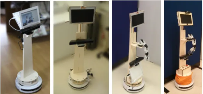
Fig. 1. Robots in RoCKIn competition. From left to right: Care-o-Bot, RITA, REEM, Sudo, ISR-CoBot
Team Robot Name University or Company name Price (euros)
n/d Care-O-Bot Fraunhofer (IPA) (Germany) +100k*
Borg RITA + MICO (kinova) University of Groningen (Netherlands) 27,000 + MICO
n/d REEM Pal Robotics (Spain) +100K*
Borg Sudo University of Groningen (Netherlands) Pioneer (5k) + MICO
SocRob ISR-CoBot IST (Portugal) tens of thousands
Watermelon MYRABot University of Le´on (Spain) 2500 C
TABLE I
TEAMS INROCKINCAMP2014
shown in table I. The table shows the Team Name (not defined means that the organi-zation, the university or a company offer it to whatever other team for testing their al-gorithms), Robot Name, University or Com-pany name and the price. The price shown in last column is estimated but it allows us to make a quickly comparison.
III. MYRABOTEVOLUTION
This section describes the MYRABot plat-form evolution. It was started in 2012, and the las prototype was shown in RoCKIn Camp 2014. This evolution can be seen in figure 3. At the beginning the platform was designed for elderly assistive tasks with two concepts in mind: offers a telepresence system and and for helping in daily tasks with augmented reality. The first will allow the elderly people to keep in touch with their family and friends. The augmented reality concept was introduced in our platform for offering a solution to improve the drug dose control in the elderly.
We started this research thinking that this solution could be deployed in a low cost platform as Turtlebot, but after a few expe-riences [2] we saw that the platform design
was not the adequate for the interaction, the height of the solution and the non-display morphology were a handicap for interacting with humans. Since this moment we decided to develop a new platform morphologically talking, for improving the interaction expe-rience but supported in the idea of low cost initiated by TurtleBot.
The first step was to select the robotic base, we should change, we should buy a new one or we should build a new one. Due to our previous experience we decided to use the same base iCreate, but it was not available in our country, so we de-cide to change to Roomba whose behav-ior and development is similar to iCreate, and also it has a feasible price. Figure 2 shows the real turtlebot and our first pro-totype (Roomba+computer+controller). The main problem related with the new base was the integration with the external sen-sors. iCreate has a parallel port ready for connecting other sensors, as for instance the kinect and also for power supply. In our case we use a hacked USB to serial interface for controlling the base and for getting the kinect power.
ence due to display position (this conclusion can also be found in literature [10]). For this reason we built a new frame able to change the display height and display angle, this frame is presented in the second picture of figure 3 and can be defined as model II.
From this experience we defined the main constraints in the frame development: a) the morphology, it has to be comfortable for interacting with humans and also it has to be able to integrate different sensors, we de-cided to build a height adjustable frame with a minimum height of 95 cm and a maximum height of 160 cm for interacting with people sitting or standing with adjustable display levelling b) the materials, it has to be easy to model, it should has low weight and it has to be mounted and unmounted easily, we chose poplar laminated wood for handling it easily in our lab and because it offers resistant to warping and shrinkage and c) the display, we need it for offering a non verbal interaction system, we already had an interactive software solution called MYRA for helping in the drug dose control and it extensively uses a display therefore we need to put in top of the robot the display to allow users the interaction with MYRA.
Our next goal after the real experiences was to add an arm to improve the interaction. We were using the AR for the interaction
Fig. 2. Turtlebot Evolution
requirements of the RoboCup competition. The main features in this evolution: the but-ton box with robot start-stop butbut-ton, Roomba start-stop button and the emergency stop button. In this last phase we also arranged all the wires along the robots using plastics leads and we covered all sharp edges with wooden cases to avoid hurting people.
IV. HARDWAREOVERVIEW
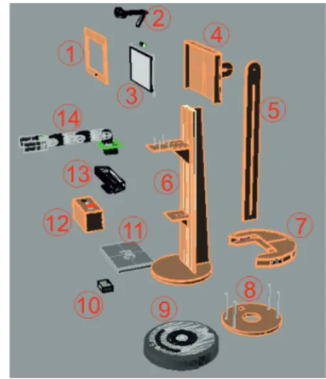
This section describes the hardware com-ponents of MYRABot, they are enumerated in figure 4.
Fig. 4. MYRABot components
A. Base
The Roomba vacuum cleaner from iRobot is our mobile base (element 9 in figure 4). This is a differential drive base whose main sensors are: bumper, infrared receiver, and cliff sensors but these sensors are not enough for classical indoor robot navigation techniques, and the kinect has to be used.
Fig. 3. MYRABot Evolution: Model I, II, III, IV
The Roomba has been modified in differ-ent aspects: a) the first one is related with the frame attachment, b) the second one is related with the full battery disconnection and c) the kill switch or emergency stop and d) output connector from main brush for feeding the arm.
B. Frame
From the hardware point of view we had to choose between different materials as methacrylate, PVC or aluminum but finally we avoid them because of the price and the difficult to handle.
We chose poplar laminated wood, it is more easy to manage with common tools. The components made of wood are: a) the display case (1,4), b) the full adjustable frame with the arm and kinect supports (5,6,8), c) the range sensors case (7) and d) the button box (12).
The poplar laminated wood is a lightweight and resistant material. The main frame is mounted in a T-shaped way to improve the resistant allowing us a light frame for avoiding base overload.
We made all the development follow-ing digital fabrication and rapid prototypfollow-ing techniques [6], [5] in a FabLab laboratory [7], [3].
We have developed a frame able to be adapted according the interaction experience, the reason is that during the interaction the individual position can be defined as stand-ing, sittstand-ing, or lying. In this way we built a manually height-adjustable system to handle
the display position and also a manually ro-tation system for the best angle visualization.
The main specs of this frame are:
• Max/min height: 1.6 m / 1.080 m
• Weight:aprox 3 kg • Display rotation: 238 º
C. Arm
The arm (element 14 figure 4) has been built using the commercial off-the-self Bi-oloid educational kit and using Dynamixel AX-12 servos. We choose this option for two reasons, the low price and they can be feed using the roomba battery.
We are using 5 motors: one motor is used to control the gripper, one motor controls to yaw movements and the other three allow us to work in the same plane so we are working with a 4 DOF arm.
Fig. 5. Arm workspace
From the software point of view, we have developed an embedded solution for educa-tional reasons but for challenge we
devel-The primesense sensor are the Kinect mounted on the frame for navigation tasks.
The two RGB cameras are mounted on top of robot. The first is the netbook integrated camera, we have moved it on the display case. The second one is a basic USB webcam used for manipulation tasks.
The problem of this kind of sensors is related with the depth data processing. The computational cost related with RGBD sen-sor is high. The computational cost related with 2D cameras is feasible in our platform and allows to deploy robot behaviors flu-ently.
E. Dialog system
We have mounted a microphone on top of the platform as an input sensor. We have re-moved the netbook’s integrated microphone and we have installed it within the display case. As an output system we have used the netbook’s built-in speakers whose placement are the base of the platform.
F. Control and Communications
The main components of control and com-munications are three:
1) Netbook: It is the process unit. It mounts an Intel Atom processor with 1GB RAM
2) Arm Control: It is an Arduino MEGA 2560 REV3 board. It mounts at AT-mega2560, Flash Memory 256 KB, SRAM 8 KB, EEPROM 4 KB and 16 MHz Clock.
3) Communication interface (CI) : the chip FT232RL is the main compo-nent. The FT232RL is a USB to serial UART interface. This interface is built in a Bus Powered Configuration
connector in the PC. The key point of this interface is the modification for getting the power supply for kinect camera (12V).
V. SOFTWAREOVERVIEW
We have designed all robot behaviors us-ing ROS software development framework (Robot Operating System). ROS has had eight official distributions until now. Since 2010 ROS released two distributions per year until 2013 the reason was that ROS was developed following the Ubuntu schedule as the main development platform. For this reason we find 6 distributions in three years. But during the last two years ROS increase support to other OS distributions and in this way they changed these policies with only one distribution per year an also with a well defined relation with Ubuntu LTS.
The robot have installed the Fuerte distri-bution but we also use some Electric pack-ages because some modules off-the-self were in this distribution and the integration with Fuerte was easy.
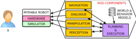
In figure 6 a high level view of ROS com-ponents integrated in the MYRABot plat-form are presented. We have a lot of de-pendencies with low ROS core packages as:
roscpp library that provides the C++ inter-face for ROS; std msgs package provides the primitives for all messages representation used in ROS; geometry msgs that provides geometric primitives such as points, vectors, and poses, orsensor msgspackage provides the the messages for most common sensors.
1) Navigation: We used the follow-ing packages: base local planner, gmap-ping , amcl or move base. The Turtle-bot navigation package provides the high level method for turtlebot navigation man-agement but for more complex task the nav-igationstack (deprecated concept in recently
ROS distributions) is required. With this stack we find the base local planner, that provides the implementation of the Trajec-tory Rollout and Dynamic Window for the robot navigation on a plane. Thegmapping
package presented as a ROS wrapper for OpenSlam’s Gmapping supported in laser-based SLAM, in our case using the data from Kinect. Theamcl package for providing the localization system and based in the adap-tive Monte Carlo localization approach. The
move base package for offering an action system for robot movement.
2) Dialog: For the dialog system we are using our own package that wraps the gstreamer-pocketsphinx library and
sound play ROS package for voice generation. The text to speech component is supported onFestivalsoftware.
3) Manipulation: This task needs of
rosserial python package for Arduino con-trol and message interchange. All the kine-matics analysis for moving the arm are per-formed in our own package.
4) Perception: We are using different ROS packages for the perception task. First, we are usingopenni camerapackage for the RGB-D sensors as Kinect or Xtion. For 2D sensors, as webcams, we are usingusb cam
and usb cam packages. We have to deploy both because hardware restrictions between the external webcam camera and the inte-grated one presented in the computer.
On top of this we are using the PCL library for object recognition and pose esti-mation using 3D cameras. Also we have our own packages for 2D recognition using the RGB webcam.
5) Planning and Execution: We have de-fined a high level component and a small database with the basic behaviors defini-tion and world modeling. This was our first approach for the challenge set up but we are working in a middleware integration for simplifying the behavior development.
This component is presented as a finite state machine that activate and deactivate the necessary or unnecessary ROS components.
The behaviors and some components vari-ables are defined previously in a database.
Fig. 6. Main software components in MYRABot
VI. SIMULATION
We have developed the MYRABot robot model for Gazebo. Gazebo is one of the most common environments for robot simulation. There are a lot of platforms available to test with it and also it has an easy integration with ROS.
We have also deployed the MYRABOT model in rviz, the 3D visualization tool for ROS.
The robot model for Gazebo is defined using URDF(Unified Robot Description For-mat). We defined the visual component with the physics characteristics by one side and the controllers in charge of the mobile unions are modeled by the other side. For educa-tional reasons we have developed the sim-ulation models in two phases, in the first phase we developed the arm, that we were using for simple kinematics research and in the second phase then we integrated this arm in the robot model for a full robot simulation.
A. Arm Model
The AX-12 servos have been modeled using the PR2 model whose main feature is the position and velocity control using a PID regulator. The arm model working autonomously can be seen in figure 7
B. MYRABot Model
The whole MYRABot model includes the base, the frame, and the robot sensors plus the arm model (figure 8).
We have used the iCreate model of Turtle-bot in ROS. We also use the kinect model
Fig. 7. Arm model in gazebo
deployed in the Turtle Bot. The other sensors are modeled as an approximate physical rep-resentation and using the plugins available in the Gazebo environment.
Fig. 8. MYRAbot model in gazebo
VII. ROCKINEXPERIENCE
The first RoCKIn camp 2014 took place in Rome in Feb 2014. The RoCKIn committee has defined for each year two phases. The first phase is focused in robot set-up and team collaboration. The second phase is fo-cused in the challenge itself working against other teams.
We found pros and cons of the proposed techniques and software presented in the camp. The major advantage was that they offered a off-the-self solutions, so all teams were able to test it. The disadvantages were mainly: a) the proposed solutions only run in Hydro, a ROS distribution different of our Fuerte version; b) the second one was the high computational cost of the proposed solutions, in our case we have a netbook
were able to identify some problems in our platform. From a software point of view, we found that ROS Fuerte distribution was too old for new software solutions. Our robot works but any other new feature has to be downgrading for Fuerte distribution.
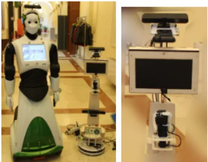
We also find two problems related with the robot hardware. The first one was re-lated with the robot sensors, we were not able to deploy some perception solutions for grasping because our 3D camera is situated in a lower position and it is used only for navigation tasks. In this way we decided to put an extra Xtion Camera on top of the robot as is shown in right picture of figure 9, it was possible thanks to the robot morphology.
Fig. 9. a) REEM and MYRABot. b) Extra camera for object pose recognition
The last problem was related with power supply, we burn our battery and were not able to feed kinect or arm without wires. The reason is that we carry our first prototype to the camp, and it was extensively used for labs experiments.
VIII. CONCLUSIONS
We have presented the evolution of a low cost robotic platform adapted for RoCKIn @home challenge.
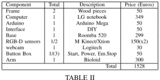
The main contribution presented in this paper is the robotic platform for interaction built. It is at least 5 times cheaper than other similar robots as seen in table II.
The second contribution is that the plat-form design enable HRI tasks as manipu-lation and grasping, and interaction through the display. It is possible to adapt it in height. Also this frame design allows us to improve the platform with new sensors if we need it. Component Total Description Price (Euros)
Frame 2 Wood pieces 50
Computer 1 LG notebook 349 Arduino 1 Arduino Mega 50
Interface 1 DIY 50
Base 1 Roomba 520 299
RGB-D sensors 1/2 M Kinect/Xtion 150(x2)
webcam 1 Logitech 30
Button Box 1/(3) Start, Power, Em.Stop 50
Arm 1 Bioloid 300
Total 1528
TABLE II
SUMMARY OF COMPONENTS BY PRICE
Our conclusions related with the robot performance during the RoCKIn challenge are: a) we were able to migrate components to adapt our platform to competition rules, as others teams; b) we were able to integrate competitions components as MoveIt to our system (adapting it to our hardware restric-tions) as is shown in figure 10; c) we have built a platform capable of making the same robotic task as the other robots but with an economically feasible platform, this make us think that this platform can be used as a first approach for other @home competitions as RoboCup.
Fig. 10. MoveIt! for planning MYRABot arm
Finally we identified some hardware
prob-lems that are difficult to be detected in a research lab, as for instance, software inte-grations issues and power problems when all hardware components were running together, or the speakers situation that presents a hand-icap for the dialog. Also the performance of our netbook computer is a handicap when we are working with RGB-D sensors, but as we presented this does not prevent us to develop parallel solutions adapted to our platform able to fulfill the tasks
ACKNOWLEDGMENT
The authors would like to thank C´atedra Telef´onica - Universidad de Le´on
REFERENCES
[1] The Technology Strategy Board. Results of competition: Active ageing-SBRI SILVER: Supporting independent living of the elderly through robotics. Web: https://www.innovateuk.org/documents/
1524978/1866952/SBRI%20SILVER%20-%20Results%20of%20Competition, July 2013. [2] Carlos Rodr´ıguez Juan Felipe Garcia Francisco
J. Rodr´ıguez Lera, ´Alvaro Botas and Vicente Matell´an. Robotics and augmented reality for ederly assistance. In XII Workshop en Agentes F´ısicos (WAF 2012), 2012.
[3] Neil Gershenfeld. Fab: The Coming Revolution on Your Desktop–from Personal Computers to Personal Fabrication. Basic Books, Inc., New York, NY, USA, 2007.
[4] BORG Research Group. Borg - the
robocup@home team of the university of groningen. Team description paper, University of Groningen, 2011.
[5] V. Hui, C. Leu, S. Ghantous, D. Duldul, J. So, and J. Ramelson. Digital fabrication in the age of collaboration. InINTED2012 Proceedings, 6th International Technology, Education and Develop-ment Conference, pages 2391–2400. IATED, 5-7 March, 2012 2012.
[6] Lisa Iwamoto. Digital fabrications: architectural and material techniques. Princeton Architectural Press, 2013.
[7] Corinne Buching Julia Walter-herrmann.FabLab: Of Machines, Makers, and Inventors (Cultural and Media Studies). Transcript-Verlag, January 2014. [8] Luca Marchionni, Jordi Pages, Jordi Adell, Jose Rafael Capriles, and Hilario Tom´e. Reem service robot: How may i help you? InNatural and Artificial Models in Computation and Biology, pages 121–130. Springer, 2013.
tion. InProceedings of the 8th ACM/IEEE inter-national conference on Human-robot interaction, pages 1–8. IEEE Press, 2013.
[11] Stephanie Rosenthal, Joydeep Biswas, and Manuela Veloso. An effective personal mobile
Meric¸li, Mehdi Samadi, Susana Brand˜ao, and Rodrigo Ventura. Cobots: Collaborative robots servicing multi-floor buildings. In IROS, pages 5446–5447. IEEE, 2012.