A Scenario-Based Approach to
Evolution of
Telecommunications Software
A
BSTRACT
Significant amounts of legacy software create a “barrier” to adoption of advanced software engi-neering techniques in the telecommunications industry. To overcome this barrier, algorithms, methods, and powerful tools for automated extrac-tion of formal models of the legacy telecommuni-cation software are required. In this article we present a “scenario-based” approach to design recovery and evolution of legacy telecommunica-tion software into formal models. Our approach is iterative and is based on extracting scenarios from the legacy software using a combination of dynam-ic and statdynam-ic strategies, and automatdynam-ically synthe-sizing formal models from these scenarios. For the first step we use the KLOCwork Suite, which is capable of providing summarized structural, func-tional, and scenario models of existing software. For the second step we use the MOST Suite, which is capable of synthesizing state-based formal models from scenarios, formalized as extended message sequence charts. The article provides detailed descriptions of our design recovery methodology and compares it with related approaches. A case study is discussed where our scenario-based methodology was applied to recov-er design of a small-sized telecommunications-like software system called the ToolExchange.
I
NTRODUCTION AND
B
ACKGROUND
The demand for high-quality efficient telecom-munications systems and the rate of change in requirements for such systems continue to increase rapidly. As a result, development time or time to markethas become as important to industrial success as product quality, price/per-formance, and development cost. Although com-puter-aided software engineering (CASE) technology and formal description techniques (FDTs) have offered promising means of deliv-ering better systems sooner, up to now thepromises have not been fulfilled. The current sit-uation, however, is showing significant signs of improvement.
First, a small number of scalable, industrial-strength CASE tools have won substantial accep-tance in industry. These include TAU and SCADE tools from Telelogic, Statechart from i-LOGIX, and Rational Rose/RT from Rational Corp. These tools provide designers with power-ful analysis, modeling, and rapid prototyping capabilities, which enable early verification and validation of designs, usually by simulation, with some dynamic state-space exploration features. The tools are stable, and support standard mod-eling languages and notations for specifying sys-tem requirements, designs, and tests.
Second, the Specification and Description Language (SDL), used primarily for representing protocols and system design specifications, has now gone through several releases as an interna-tional standard language [1], together with the corresponding scenario description language Message Sequence Chart (MSC) [2]. As a result, among the FDTs supported by the International Telecommunication Union (ITU), SDL and MSC are by far the most widely adopted for industrial use. The ongoing convergence of SDL and MSC with the Unified Modeling Language (UML) within the Object Management Group (OMG) and ITU [3] is an indication of the grow-ing adoption by industry.
A number of very successful industrial pilot studies have recently been completed, claiming improved quality, much lower development cost, and decreases in time to market of 20–50 per-cent. Some of this increased designer productivi-ty and system qualiproductivi-ty comes directly from the use of an integrated modeling environment: doc-umentation is generated as development pro-ceeds, design decisions are traceable to requirements represented as MSCs (scenarios), code is generated automatically, designs can be simulated before production code is produced,
N. Mansurov, KLOCwork Solutions Corp
Robert L. Probert, University of Ottawa
E
VOLVING
C
OMMUNICATIONS
S
OFTWARE
:
test cases can be produced semi-automatically or automatically in some circumstances, and so on. We believe that savings in development time actually come from better designs produced with the use of these industrial-strength design and development tools, since better designs will require substantially less rework and redesign. In addition, in a recent pilot study by TSERG and Mitel Electronics [4], it was found that a CASE-based approach could be used to develop func-tional test specifications for complex telecommunications systems several times faster than current technologies allow. Thus, CASE-based approaches (often using SDL tools) offer significant improvements in quality, productivity, and time to market.
However, in order for CASE-based telecom-munications software engineering to become common practice, it is necessary to provide cost-effective methods for integrating CASE-pro-duced components and systems with older, legacy base software. Legacy software systems were produced with older development methods, often involving a blend of higher-level code, and system-level code, with heterogeneous languages, architectures, and styles, and were often very poorly documented. Up to now, this fact has constituted a legacy barrierto the cost effective use of new development technologies.
In order to overcome the legacy barrierand protect the investment in existing telecommuni-cations software, there is an increasing demand for automatic (or semi-automatic) design recov-ery and evolution methods, which will signifi-cantly reduce the effort involved in creating formal models of existing software. In order to increase adoption of advanced software engi-neering techniques in the telecommunications industry, such methods should also protect the investment into existing standards and the corre-sponding tools. Thus a software evolution methodology should provide a seamless migra-tion strategy from existing code into one of the modern CASE-based environments.
This is the motivation for the research per-formed by KLOCwork Solutions — an indepen-dent start-up company, which spun out from Nortel Networks (Canada) to develop time-to-market technologies for the telecommunications sector. The main research direction of KLOC-work Solutions is to design a methodology for providing architecturally significant high-level models of existing software, such as summarized UML package model, component model, pro-cess and object models [5] as well as summarized scenario models and collaboration models [6]. To complement maintenance activities, a for-ward engineering methodology was designed, supporting rigorous use case modeling with UML and the ITU scenario language MSC, and also supporting automatic transformation between the two ITU standard formal specifica-tion languages — MSC and SDL. The MOST Suite [3] is integrated with the leading SDL development environment — Telelogic TAU.
In this article we present our scenario-based methodology for design recovery and evolution of legacy telecommunications systems. The design recovery approach consists of iteratively: • Approximating the original use case
scenar-ios of the system as a formal MSC scenario model, using dynamic or static techniques, or a combination of both, using the KLOC-work Suite [5, 6] for processing existing software
• Synthesizing a formal state-based model from this set of scenarios in SDL using the MOST Suite [3]
This process is repeated until the state-based design model satisfies certain validity constraints. The resulting model can be seamlessly imported into an SDL environment, for example, for devel-oping and validating new features. We selected SDL as the notation for the state-based models because it is already a widely adopted telecommu-nications standard, as well as because of the excellent tool support available for this language.
The rest of the article has the following orga-nization. We provide an overview of our sce-nario-based design recovery and evolution methodology. Detailed steps of the methodology are described, and we illustrate our approach by discussing a case study. The article contains some comparisons to related approaches and then concludes.
M
ETHODOLOGY
O
VERVIEW
Scenario-based design recovery extracts scenar-ios from the existing system, and then uses auto-matic synthesisto produce a formal state-based model from these scenarios (Fig. 1). The enabling technology for this approach is auto-matic synthesis of state-based models from a set of MSCs [1]. So far automatic synthesis of state-based models from MSCs was considered only as a forward engineering technology. We exploit the duality of MSCs as both a requirements cap-turing language and a trace description lan-guage. This allows us to treat dynamic probe traces and/or static source threads as require-ments for a state-based model.We define primaryscenarios as sequences of interactions defined by the customer. Primary scenarios are important paths through the core use cases of the system, where everything works and the user achieves his goal. The erosion of the knowledge of these primary scenarios usually hinders evolution of a software system.
Our scenario-based methodology allows approximating the lost primary scenarios by ana-lyzing the only two reliable sources of informa-■Figure 1.An overview of the methodology.
Refold loops
Execution of instrumented system
Probe traces Source threads
State-based model Source code Core tests MSC model Automatic Manual Legend Synthesis Navigating
tion about the system: the source code and the core test cases.
The dynamic strategy is a black-box approach that uses the core test cases to represent the pri-mary scenarios functionally. The design of the primary scenarios is recovered through building and executing the source code with strategically embedded probes.
On the other hand, the static strategy is a white-box approach, which analyzes the code to identify the key design components to statically infer the execution threads corresponding to the primary scenarios.
D
ETAILED
S
TEPS IN THE
M
ETHODOLOGY
P
HASE1:
P
REPARATIONThe aim of this phase is to collect initial informa-tion about the system and make decisions about the structure of the model to be recovered. Step 1. Collect known primary scenarios and regression tests —Any prior knowledge of the primary scenarios dramatically focuses and accelerates the design recovery process. Known primary scenarios can be further elabo-rated and converted into source threads using our static recovery strategy.
The dynamic capture of probe traces is driven by the test suite. We suggest that the (legacy) regression test suite of core functional test cases be used to drive the first iteration of scenario-based methodology. Regression tests consist of a blend of conformance tests and primary scenarios, which are certified by the corporation as desired behaviors. To make iterations converge, we add additional functional scenarios as required. Step 2. Select the modeling viewpoint — Our approach may be used to recover design models of the legacy code from a black-box (environment), white-box (core code), or grey-box (collaborations among subsystems) point of view. Viewpoint affects the level of detail in sce-narios and therefore determines the structure of the resulting state-based model.
Step 3. Analyze code — This step uses archi-tecture analysis, provided by the KLOCwork Suite [5], to locate more primary scenarios and select probe placements. Two models of soft-ware can be used as guidelines for probe place-ment: the summarized structural model of the system (major components and their relation-ships) and the functional model of the system (e.g., the object model or call graph).
Step 4. Set a coverage goal and select probe placements — At this step we finalize probe placement by selecting particular locations in the source code of the system where probes are to be placed. By selecting the coverage goal we control the level of detail in traces and also define the external interface of the recovered model.
In order to achieve approximation of the original intended use cases of the system,
so-called semantic probingis performed. The cover-age goal is not phrased in terms of syntactic enti-ties such as statements or branches, but in terms of semantic entities, namely equivalence classes of program behavior [7]. These equivalence classes of program behavior are determined solely from the system design. Therefore, probe traces obtained by executing instrumented code can be used to recover the system design. Semantic source threads can also be extracted directly from the source code using our static extraction strategy. See the “ToolExchange Case Study” for an illus-tration of different probe placement strategies.
P
HASE2:
A
PPROXIMATINGO
RIGINALU
SEC
ASES BYT
RACES ANDT
HREADSThe aim of this phase is to build an approxima-tion of the original use cases with traces (dynam-ic strategy) and threads (stat(dynam-ic strategy). A practical design recovery process should use a combination of both strategies to achieve rapid convergence of iterations.
Dynamic Collection of Probe Traces — The aim of this phase is to capture the set of probe traces, which correspond to the probe placement strategy and selected core tests.
Step 5. Instrument source code — A suitable probing infrastructure for generation and collec-tion of probe traces needs to be established. Probes are inserted into the source code accord-ing to the placement strategy. We use a very sim-ple and powerful instrumentation technique, consistent with our semantic probing approach. Using the KLOCwork Suite [5], we identify the functional interfaces of components we want to model. Then for each function in such an inter-face we create a macro with the same name, which contains statements to generate events before and after the call to the original function. Step 6. Execute the instrumented system to generate probe traces — The instrument-ed system neinstrument-eds to be built and executinstrument-ed accord-ing to the core test suite. The target or simulated environment together with the existing testing infrastructure is used. One output of this step is a set of probe traces. Another output of this step is the probe coverage metric.
Static Extraction of Source Threads
Step 7. Extract source threads — In order to complement the dynamic approach, certain important primary scenarios can be captured without building and executing the system. Pri-mary scenarios can be extracted statically by nav-igating through the source code and capturing the corresponding events. Reference [6] describes this method and presents cost-effective support based on the KLOCwork Suite [5]. Stat-ic capturing of scenarios leads to fewer but at the same time more informative scenarios, which provide a better approximation of the design intentions of the system. One output of this step is the set of source threads. Another output of this step is the thread coverage metric.
Our
scenario-based
methodology
allows
approximating
the lost primary
scenarios by
analyzing the
only two reliable
sources of
information
about the
system: the
source code and
the core test
cases.
P
HASE3:
S
YNTHESIS OF AS
TATE-B
ASEDM
ODELThis is the key phase in our methodology. The aim of this phase is to synthesize a state-based model of the system under evolution.
Step 8. Translate probe traces into event-oriented MSCs — This step was introduced into the methodology in order to separate two different concerns: capturing scenarios from legacy using a combination of dynamic and static techniques, and synthesizing state-based models from scenarios. This step performs a translation between traces and threads into MSCs. This step handles the differences between the formats of probe traces and of input to the synthesizer tool. Step 9. Refold loops in probe traces — The aim of this step is to recover loops in the probe traces that were unfolded during execution. This step is not required for source threads, because information about loops is manifestly obvious from the source code and preserved in threads. The presence of loops in scenarios leads to syn-thesis of state-based models with much more interesting behavior.
Step 10. Synthesize the state-based model —This step is done automatically by importing scenarios into the MOST Suite and running the MOST-SDL synthesizer tool [3].
The outputs of this step are: • The synthesized SDL model
• The number of states in the SDL model • A nondeterminism metric of the model
The last metric is an indirect termination cri-terion for the design recovery process. A nonde-terministic choice is generated each time two or more input scenarios have different behaviors on the same external stimulus. In practice this often means that behavior of the system is determined by previous history, but the traces captured dur-ing the previous steps do not contain enough data. High values of the nondeterminism metric should lead to further iterations of the design recovery process.
P
HASE4:
A
SSESSMENT OF THES
TATE-B
ASEDM
ODELThe aim of this phase is to check termination criteria by evaluating the probe coverage, thread coverage, and nondeterminism metric.
Step 11. Terminating criteria — We need to make sure that the synthesized model adequately captures the behavior of the system under evolu-tion. This may require several iterations of the design recovery process. Inadequate behavior of the model may be caused by at least two factors: • A missed primary scenario
• A missing or incorrectly placed probe
In our experience, missed primary scenarios can be correlated with incomplete probe or thread coverage. Incorrectly placed probes result in incomplete probe coverage. Missed probes result in high values of the model nondetermin-ism metric. Thus, the probe coverage, thread coverage, and nondeterminism metric together
can be used as terminating criteria.
It is important that terminating criteria allow detecting inadequacies in the legacy test suite, in which case the synthesized model can be used to generate additional test cases [4].
T
OOL
E
XCHANGE
C
ASE
S
TUDY
We have applied our methodology to recover design models of a small-sized telecommunica-tions-like system called the ToolExchange.D
ESCRIPTION OF THET
OOLE
XCHANGES
YSTEMThe ToolExchange implements a simple lightweight text-based protocol for communica-tion between loosely connected interactive tools in an extensible multicomponent CASE environ-ment. The ToolExchange provides interoperabil-ity between components by allowing them to perform remote services.
The ToolExchange supports the following functionality. Each tool has a unique symbolic name. When a tool dynamically connects to the ToolExchange it is registered at the ToolEx-change as a subscriberwith a unique identifier. A service can be requested based on either a sym-bolic name or a unique identifier. When the ser-vice is requested via a symbolic name, the ToolExchange first checks if there is any active subscriber with this name. If an active subscriber exists, the ToolExchange sends the service request to it. If no active subscriber exists, the ToolExchange launches the tool using the tool command linecorresponding to that name. When the service is requested via a unique identifier, the ToolExchange checks if the subscriber is still connected and sends the service request to it.
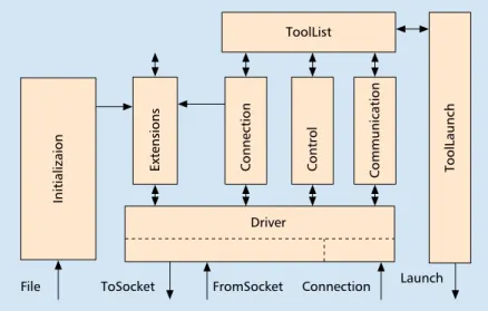
A
NALYSIS OF THES
YSTEMA structural view of the ToolExchange is present-ed in Fig. 2. Rectangular boxes represent compo-nents. Lines represent relationships between components (usually implemented via function calls; each line can represent several function calls; direction of lines represent the direction of function calls). Lines between components and the frame of the picture represent external inter-faces of the system. Such structural diagrams can be automatically produced from the source code of the system using the KLOCwork Suite [5].
The Drivercomponent implements the
low-level protocol based on UNIX sockets. The
Drivercontains the main event loop, which
handles messages from already opened sockets (interface FromSocket) as well as new connec-tions (interface Connection). It also encapsulates sending messages to sockets (interface ToSock-et). The Drivercomponent consists of several modules: low-level socket communication, socket connections, interpreter of the low-level message format, and so on. The Initialization com-ponent allows reading an initial sequence of requests from a file (interface File). The
Tool-Launch component implements the protocol
for launching new tools (interface Launch).
The ToolListcomponent represents the key
abstraction of the ToolExchange — the list of current subscribers. This list is used to search for an active subscriber with a given name. Elements of this list can be marked as active or locked
The ToolExchange
implements a
simple
lightweight
text-based
protocol for
communication
between loosely
connected
interactive tools
in an extensible
multi-component
CASE
environment.
based on requests from Controlcomponent, which implements the logic of processing requests performed internally by the ToolExchange. The
Connectioncomponent represents the logic of
adding new subscribers. The Communication component represents the logic of handling ser-vice requests. The Extensionscomponent is beyond the scope of this case study.
Implementation of the ToolExchange system consists of 14 modules in C++ language. The implementation contains 110 functions. The total size of the implementation is 1128 LOC. There is a small regression test suite consisting of 15 test cases.
D
ERIVINGS
CENARIOSFirst, we applied the dynamic extraction strategy. We have experimented with three different probe placement strategies using the same test suite (Table 1). Names of the probe placement strategies are given in the second column and are referred to by subsequent tables.
Table 1 gives a brief explanation of each probe placement strategy and shows the volume of the generated MSC models (converted from probe traces) for each probe placement strategy. The volume of the trace is roughly the product of the number of events and the amount of data handled by each event. As expected, traces of the higher-level protocol have less volume than
the lower-level protocol. Investigation of the probe coverage after the first iteration allowed us to place probes on some additional functions, which significantly improved the coverage (and hence the volume of the trace).
Second, we applied the static extraction strate-gy. Considering the size of the system, it was very easy to extract 11 scenarios that exactly correspond to the original use cases of the system. These sce-narios consist of 493 LOC MSCs, which is quite close to scenarios, extracted dynamically according to the high-level probe placement strategy.
Table 2 shows the resulting probe coverage of components. Columns of the table correspond to the probe placement strategies. Most of the probe hits are inside the Drivercomponent. It is interesting to observe that moving to a low-level placement strategy from a medium-low-level one did not increase the coverage of the high-level components.
S
YNTHESIZINGSDL M
ODELS FROMS
CENARIOSU
SING THEMOST S
UITEWe applied the MOST-SDL Synthesizer Tool [3] to MSC models captured at the previous step. We also examined MSC models and refolded loops. Table 3 summarizes synthesized SDL models. Table 3 shows the volume of the synthesized SDL models, the number of states in each SDL model, and the nondeterminism metric (number of any) of each SDL model (step 10 of the methodology). An analysis of Table 3 shows that high-level probes cause less nondeterminism than medium-level probes (lines 1 and 3, also lines 5 and 6). Refolding loops in the medium-level model leads to a dramatic reduction in size of the synthesized SDL model (lines 1 and 2, also lines 3 and 4).
We observed that higher-level probes result in more meaningful models. This happens because more logical information becomes avail-able as probes are inserted higher in the call graph of the system. It is thus easier to relate high-level information to the architectural and logical models of the system.
R
ELATION TO
O
THER
A
PPROACHES
AND
C
ONCLUSIONS
We have presented our scenario-based approach to design recovery and evolution of legacy telecommunications software. The objective of ■Figure 2.Architecture of the ToolExchange.
Launch Connection FromSocket ToSocket File Communication ToolLaunch Initializaion ToolList Driver Control Connection Extensions
■Table 1.Probe placement strategies.
Iteration Name Description MSC (LOC)
1 Medium-level Probes inserted inside the Driver component 610 (at functions, encapsulating message send and receive) 1 High-level Probes inserted at high-level interface of the Driver 408
component
2 Low-level Probes inserted at the operating system interface 44,852 2 Medium-level Probes inserted at complete medium level (12 more 10,000
functions added)
2 High-level Probes inserted at complete high level (2 more 1600 functions added)
our methodology is to overcome the “legacy bar-rier” to the cost-effective use of advanced soft-ware engineering techniques, which include formal modeling and component-based develop-ment. Therefore, the core of our evolution methodology is an automated and adaptable design recovery process. Our approach to design recovery consists of iteratively:
• Extracting scenarios from the system under evolution using a combination of dynamic and static strategies to approximate the original use cases of the system as a formal MSC model, using the KLOCwork Suite to handle existing sources
• Automatically synthesizing a state-based model in SDL from these scenarios using the MOST Suite
Most telecommunications systems have evolved nonsystematically over many years. Each upgrade in functionality or performance involves some incremental modification to the code, and possibly to the system architecture as well. To add new components to an existing (legacy) sys-tem without understanding the syssys-tem’s design is tantamount to courting disaster. For example, a new component that provides a new pro-grammable feature capability may be added as a type of switch peripheral. In this case, it is neces-sary to understand at least some of the design aspects for the switch-to-peripheral interface. However, design rationales are no longer avail-able or were not documented properly in the past. As a result, our technique for recovering the design of the switch-to-peripheral interface control logic will be helpful for planning the design and integration of new functionality in a telecommunications system.
Design recovery should also be helpful in cases where the documentation for recently developed systems is erroneous or incomplete. We can envis-age a process milestone or checkpoint that requires the modeling of existing logic and behav-iors with respect to key interfaces before design of new components is allowed to proceed.
The key new idea of our approach is to use scenarios for design recovery and evolution by providing a seamless migration strategy from existing code into a modern CASE-based envi-ronment based on widely adopted standard for-mal specification languages. Scenarios are effective because:
• Scenarios are directly related to require-ments.
• Scenarios can be recovered using a combi-nation of dynamic and static techniques. • Meaningful state-based models can
auto-matically be synthesized from scenarios. • Scenario models can easily be extended
(essential for the software evolution).
Our techniques for extracting scenarios are different from techniques of program slicing, which are based on data flow analysis [8]. The output of slicing is a subset of source code, whereas the output of our phase 2, “Approxi-mating use cases by traces and threads,” is a col-lection of significant scenarios. In addition, program slicing is based on data flow analysis restricted to only a few variables, whereas we focus on a few significant behaviors (primary scenarios); that is, we take a more holistic view.
Several other groups have suggested dynami-callyextracting scenarios from existing systems. For example, dynamic extraction of scenarios was used for the purpose of understanding an architecture [9]. However, this group used very precise instrumentation, which led to vast infor-mation space. Special tool support in the form of condensed visualization was required to aid understanding of these traces. In contrast, our approach advocates semantic probing, which leads to compact and more meaningful scenario models. Moreover, we also utilize static extrac-tion strategy, and therefore can capture fewer, more informative scenarios.
The alternative approach to recovering state-based models of legacy software is so-called direct recovery. The direct recovery approach derives a state-based model statically from source code by performing some semantics-preserving transla-tion. For example, Holzman reported automated recovery of state-based models for verification purposes [10]. The design recovery reported in [10] was greatly aided by the fact that the source code contained a special-purpose macro notation, which made states and transitions explicit. Recov-ery of data operations was done through a manu-ally maintained statement map.
Compared to the direct recovery approach, our scenario-based approach has greater poten-tial for creating higher-level state-based models. This avoids the propagation of existing “spaghet-ti code.” Dynamic deriva“spaghet-tion of scenarios is a cost-effective way to capture data operations.
Our design recovery process is highly adapt-able, because extraction of scenarios is con-■Table 2.Probe hits per component.
Component High-level Medium-level Low-level
Driver 286 1553 9840 Communication 37 74 74 Connection 14 186 186 Control 2 14 14 Extensions 47 89 89 Initialization 0 122 186 ToolList 0 80 80 ToolLauncher 0 71 71
■Table 3.Assessment of synthesized SDL models.
Iteration Probe placement Refolding of SDL (LOC) No. states No. any
strategy loops
1 Medium-level No 554 68 11
1 Medium-level Simple loops 120 7 4
1 High-level No 250 12 6
1 High-level Yes 155 1 11
2 Medium-level No 9784 1391 14
trolled by the following inputs: • Modeling viewpoint
• Probe placement strategy • Static extraction strategy
Our approach can be used to recover design models of the system under evolution from a black-box (environment), white-box (core code), or grey-box (collaborations between subsystems) point of view. Viewpoint as well as extraction strategies affect the level of detail in scenarios and therefore determine the structure of the resulting state-based model.
Our scenario-based approach uses the plat-form of the KLOCwork Suite, which is capable of providing architecturally significant high-level models of existing software, including summa-rizedUML structural, functional, and scenario models, and uses the MOST Suite to offer a seamless migration strategy from existing code into modern SDL-based software engineering environments. Our scenario-based approach appears to be a highly effective and efficient means of recovering core user intentions, and therefore core system behaviors. This provides a starting point and some necessary guidance for the orderly evolution of telecommunications software. We believe that our scenario-based evolution methodology can close the gap between tool support for so-called green field projects and maintenance of existing systems, and help remove the “legacy barrier” to adop-tion of advanced software engineering tech-niques in the telecommunications industry.
R
EFERENCES[1] ITU-T Z.100, “Specification and Description Language SDL,” Geneva, Switzerland, 2001.
[2] ITU-T Z.120 (11/99), “Message Sequence Chart (MSC),” Geneva, Switzerland, 2001.
[3] N. Mansurov and D. Zhukov, “Automatic Synthesis of SDL Models in Use Case Methodology,” Proc. 9th SDL Forum, Montreal, Canada, June 21–26, 1999, pp. 225–40. [4] R. L. Probert, H. Ural, and A. W. Williams, “Rapid
Gen-eration of Functional Tests Using MSCs, SDL and TTCN,”
Comp. Commun. J., vol. 24, 2001, pp. 374–93. [5] N. Rajala, D. Campara, and N. Mansurov, “inSight Reverse
Engineering Tool,” Proc. ICSE ’99, 1999, pp. 630–33. [6] N. Mansurov and D. Campara, “Using Message Sequence
Charts to Accelerate Maintenance of Existing Systems,”
Proc. 10th SDL Forum, Denmark, 2001, pp. 19–36. [7] R. Probert, “Grey-Box (Design-Based) Testing
Tech-niques,” Proc. 15th Hawaii Int’l. Conf. Sys. Sci., 1982, pp. 94–102.
[8] S. Horwitz, T. Reps, and D. Binkley, “Interprocedural Slicing Using Dependence Graphs,” ACM Trans. Prog. Lang. and Sys., vo. 12, no. 1, Jan. 1990, pp. 26–60. [9] D. Jerding and S. Rugaber, “Using Visualization for
Architectural Localization and Extraction,” Proc. 4th Wkg. Conf. Reverse Eng., 1997, Amsterdam, The Netherlands, pp. 56–65.
[10] G. Holzman and M. Smith, “A Practical Method for Verifying Event-Driven Software,” Proc. ICSE ’99, 1999, pp. 597–607.
B
IOGRAPHIESROBERTL. PROBERT([email protected]), Ph.D. (computer science, University of Waterloo, 1973) is currently professor and coordinator of the Telecommunications Software Engi-neering Research Group at the University of Ottawa. He is a principal investigator in communications software engi-neering for Communications and Information Technology Ontario (CITO), one of the Ontario Centres of Excellence. He was the founding director of the School of Information Technology and Engineering at the University of Ottawa in 1997. His research interests and publications are primarily in testing and quality of protocols and communications software. He has contributed to international standards in
comformance testing, including the conception and proto-typing of the TTCN Workbench, a complete environment for test suite engineering. He co-chaired TestCom 2000, the 13th IFIP Symposium on Testing Communicating Sys-tems, co-chaired the 10th International IFIP Symposium on Protocols, and founded the ACM Symposium on Principles of Distributed Computing. He has frequently collaborated in software engineering research with industry and govern-ment. In 1989 he received the Bell-Northern Research Presi-dent’s Award of Excellence for work in university-industry interaction and for contributions to technology and inter-national standards for testing communications software. In 1990 he and his TTCN Workbench development team received a TRIO Industrial Feedback award for “creating an innovation of great potential industrial utility.”