1 Page 1-6 © MAT Journals 2017. All Rights Reserved
E-call Complaint Service Using GSM and GPS Based on
Embedded System
R. Kamalakannan1,N. Ravi Kumar2
Assistant professor1,2, Department of EEE1,2, S.A. Engineering college1,2,Chennai1,2, India1,2
[email protected] Abstract
In a very critical situation many vehicles face accident in India, due to this lot of human death occurs. After that accident, some life cannot be saved due to lack of information, time and region. In this proposed system, we will provide an optimum solution to this draw back. E-call is the telecommunication carrier aimed to offer the automatic notification of the street accident based at the GPS positioning and provision of E-name prioritization within the GSM communication. Suppose when a person met with an accident, the place of the vehicle can be identified by using GPS immediately and emergency number stored in the microcontroller will send accident location as SMS message through GSM modem. Initiative calls from emergency number to relatives, ambulance, police and fire service which are already stored in the server database. With the help of the E-call telecommunication service, the recipient can trace the location which helps to save many life. So, as soon as the recipient reaches the location they will try to save the life of the victim.
Keyword: GSM, GPS, E-Call, SMS, Crash, Victim, PIC, PSP, PEIE, MTPC, WDT, ICSP, MSD, USART, SPI, IIC, SSP, FEC, STOP,PSAP, CRC.
INTRODUCTION
When a vehicle met with an accident in remote areas such as highways, hilly areas, etc. Some people's life can be lost due to communication delay about the accident. Our crash notification system is overcome the above drawback and save many
people's life. If accident occurred,
microcontroller based system will measure accident severity using crash sensor. This sensor output exceeds the threshold value, GPS identifies the location of the accident. The PIC microcontroller is programmed to send alert message with longitude and latitude value of the accident location to Public Safety Answering Point (PSAP) using GSM modem. Immediately PSAP will make voice calls to relatives, ambulance, police and fire service which are already stored in the server database. The aim is to improve accident notification and to provide fast emergency assistance. The goal of this project is to develop an end to end embedded solution which aims
at reducing the time it takes for emergency service vehicles to arrive at the accident spot. In the already existing system, if an accident happens it will be intimated to the emergency services by a manual call only.But in the proposed system it automatically call emergency operators in the event of a road accident and helps the emergency response vehicle driver o reach the accident spot quicker by using a Google maps navigation guiding device. The service provider arranges for the necessary help. Accident Detection and Reporting (ADRS) which can be placed in any vehicle uses a sensor to detect the
accident [1]. The E-Call is a
telecommunication service aimed to
provide the automatic notification of a road traffic accident, based on precise GPS-based positioning and provision of E-Call prioritization within the mobile communication network[2]. It is necessary to develop a method enabling detection of the road collision, similar to the one used
2 Page 1-6 © MAT Journals 2017. All Rights Reserved
in airbag systems, based on the signals available from the acceleration sensors[3]. This system features a crash detector and an E-Call box, which can be connected over a wired or wireless link[4].
EMERGENCY CALL SYSTEM
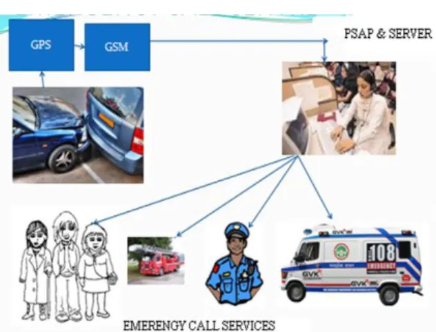
The block diagram description of the E-call system is shown in the figure 1. E-Call was described as emergency call generated either automatically via activation of in-vehicle sensor or manually by the in-vehicle occupants when activated, it provides notification and relevant location informati on identified using GPS and send this information as SMS message to PSAP using command signal in GSM.
Fig 1 Block diagram description of the E-call System
It carries a defined standardized minimum set of data, notifying that incident place and requirement of emergency services. Immediately establishes an audio channel between the PSAP server and emergency services to save accident people life.
Functioning of E-Call Services
In figure 2 shows the functioning of E-call services, the accident severity is measured by the sensor and identifies the location using GPS. E-call is expected MSD information from GSM and immediately establishment the voice call for emergency services at PSAP. Server databases in PSAP are maintaining the details about the vehicle occupants.
Fig 2 Functioning of E-Call Services Characteristics of E-Call
E-call is a post incident emergency system that uses the emergency telephone system. E-Call, which triggered from the vehicle, works by creating a priority voice channel communication between the occupants of the vehicle and a Public Service Answering Point. Before voice contact is established between the PSAP operator and the occupants of the vehicle, E-call sends a 'Minimum Set of Data' about the vehicle and the situation, as data in a voice channel, down the line to the PSAP. E-call then opens the voice channel to enable the PSAP operator to speal to the occupants of the vehicle.
Requirements of E-Call
The data may be sent prior to, in parallel with, or at the start of the voice component of an emergency call.
The realization of the transfer of data
during an emergency call shall minimize changes to the originating and transit network.
each the voice and facts factor of the
emergency call will be routed to the same PSAP or designate emergency name centre.
The transmission of the information
will be mentioned and if important facts will be retransmitted.
A UE configured most effective to
switch records throughout emergency calls shall no longer generate signaling
3 Page 1-6 © MAT Journals 2017. All Rights Reserved
to the network besides what is wanted to area and emergency name.
The UE shall imply at call setup if the
emergency call will bring
supplementary facts.
The MSD ought to normally be made
to be had to the PSAP within 4 seconds.
A call progress indication shall be
provided to the user while the SMS transmission is in progress.
The MIEC and AIEC may be used to
filter or route E-Call to a dedicated PSAP operators.
Throughout the duration of the
emergency call and following receipt of the MSD by the PSAP.
It shall be possible for the PSAP to
instruct the IVS to terminate the E-Call.
E-Call In-Band Modem Architecture
The E-Call system uses an in-band data modem to transmit the MSD information over the voice path to the PSAP. This approach enables the E-Call solution to be quickly deployed end to end in vehicle IVS's and PSAPs without modifications to
the existing cellular and wireless
infrastructure. Modem pair consisting of transmitter and receiver at IVS and PSAP that operates full-duplex and allows reliable transmission of E-call MSD from IVS to PSAP via the voice channel of the emergency voice call through cellular and PSTN network. It is a challenging task to transmit data over the mobile voice channel as required of an in-band modem since speech codes used in digital cellular systems are optimized explicitly for speech signal compression.
After an emergency voice call has been mechanically established, the IVS modem
receiver continuously monitors the
incoming signals from the speech decoder output.The requirement about the modem to be configured in either push or pull
mode is beyond the scope of this specification.
Operation of IVS Data Modem
When prompted by a signal from the PASP operator, the IVS connects the IVS data modem to the input of the speech codec and mutes any speech from the motorist for the duration of MSD transmission to prevent it from interfering with the E-Call data transmission. The MSD information input into the IVS data modem is first appended with Cyclic Redundancy Check(CRC). These bits are then encoded in the Hybrid-ARQ encoder using forward error correction coding to reduce the susceptibility to transmission errors. The Hybrid-ARQ encoder employs a very powerful turbo scheme with incremental redundancy added for each
transmission. The signal modulator
converts the encoded records into
waveform symbols which are mainly suitable for transmission via all varieties of speech encoders employed in present cell
structures, together with the GSM
complete-fee and the numerous modes of AMR encoders like 12.2,10.2,7.95.6.7. and 4.seventy five kbps.12.2,10.2,7.95.6.7. and 4.75 kbps.
Operation of PSAP data modem
The E-call PSAP receiver constantly monitors the incoming sign form the PSTN. whilst the E-name records signal is detected the outgoing speech route is muted and the sign demodulator detects the incoming data symbols. The H-ARQ decoder smooth combines the primary MSD transmission with any retransmission information and decodes the FEC to determine the statistics the data bits, i.e., its estimate of the CRC protected the IVS transmitter to provide retransmission with incremental redundancy. Otherwise, the MSD information is provided to the PSAP operator and the transmitter is notified that retransmission is not or no longer required. vii) Design Specification
4 Page 1-6 © MAT Journals 2017. All Rights Reserved Resistor R1 and R2 maintain line load
regulation.
At the secondary side of the
transformer, Applied voltage = 15V
Conducting drop across the diodes =
2*0.6 = 1.2V without capacitor: Vavg =
(15-1.2)V = 13.8c pulsating DC
Frequency = 100Hz with capacitor V =
Vavg*1.41(from factor) = 19.51V
Frequency = 0Hz with 7812 voltage
regulator: Vo = +12V
With 7812 voltage regulator: Vo =
-12V
GSM AND GPS
It describe the hardware interface of the SIMCOM SIM300 module that connects to the specific application and the air interface. GSM module and it can be
integrated with a wide range of
application.
SIM300 functions are described as given below
Off - SIM300 is not running.
64ms On/0.8 sec Off - SIM300 does
not find the network.
64ms On/3sec Off - SIM300 find the
network.
64ms On/0.3 sec Off - GPRS
communication.
SIM card Interface
The SIM interface supports the capability of the GSM phase 1 specification and additionally supports the capability of the new GSM segment 2+ specification for instant 64 kbps SIM intended to be used with a SIM application Toolkit. both 1.8V and three.0V SIM cards are supported. The SIM interface is powered from an inner regulator within the module having nominal voltage 2.8V. All Pins resets as outputs using low.
GPS
The global Positioning gadget (GPS) is a area-based satellite tv for pc navigation machine that gives vicinity and time facts
in all weather conditions, anywhere on or close to the Earth in which there's an unobstructed line of sight to 4 or extra GPS satellites.
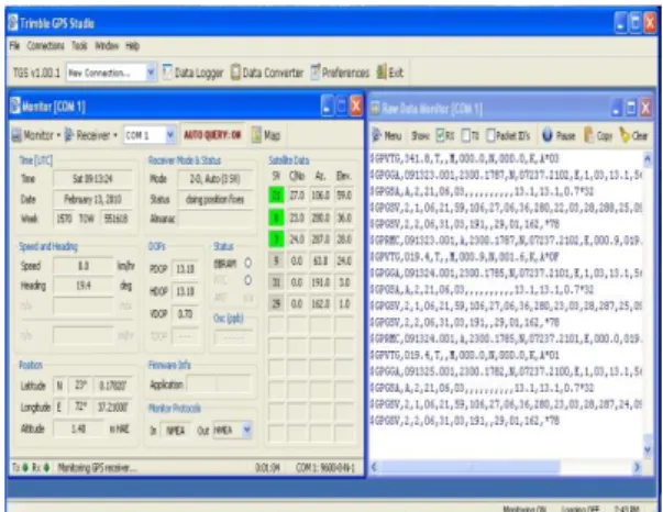
GPS output using Trimble GPS studio
First GPS device is connected to PC
using RS232 cable.
This is automatically identifies the
location of the area using software namely Trimble GPS studio.
The software output in Figure 3 is
displayed the area in the form of longitude and latitude value.
Google maps specify the location by
using the above values.
Fig 3GPS Output CRASH SENSOR
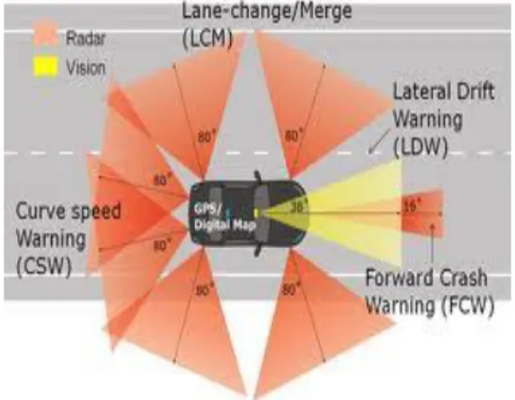
In Figure 4, sensors are placed in the car with different position. Radar based six red sensors output is measured with 80 degree severity of the accident and one in front red sensor is used to measure 16 degree accident effect. Vision based sensor is captured with 30 degree accident effect at top of the car and specified in Fig 6 as yellow color. The following warnings are produced due to accident severity and sensor position.
Lane-change merge
Lateral drift warning
Curve speed warning
5 Page 1-6 © MAT Journals 2017. All Rights Reserved Fig 4Crash sensor position
Threshold value
The following threshold values for different sensor position.
1. 50 km/h R & L Side 2. 55 km/h L.60° Rear 3. 55km/h R.60° Rear 4. 60 km/h 0° Rear 5. 56 km/h R. 60° Frontal 6. 56 km/h L.60° Frontal 7. 64 km/h 0° Frontal SOFTWARE IMPLEMENTATION
The CCB software in figure 5 is used to compile the assembly level program for
PIC microcontroller. This assembly
program is converted into .HEX code and burned into PIC microcontroller using RS232 serial cable.
Fig 5 software module PROTOTYPE MODEL
The microcontroller based E-Call system is implemented and shown in Figure 6. This system contains the following components
1. PIC Microcontroller
2. MAX 232
3. Power supply unit
4. GPS
5. GSM
Fig 6Prototype model
The Figure 7 illustrates about the accident location obtained from the GPS module in the form of latitude and longitude values. These values are sent to PSAP server through SMS.
Fig 7 PSAP server SMS
It is a back hand process, where the PSAP server maintains the vehicle user details in figure 8.
Fig 8 Database of PSAP Server CONCLUSION
The E-Call has presented as a novel contribution to enhancement public and
6 Page 1-6 © MAT Journals 2017. All Rights Reserved
traffic safety, with considerable
socio-economic benefits. The E-Call
development passed the feasibility,
research and standardization, phases and enters the testing and validations phases. The designed E-call system is used to save thousands of automotive accident victim lives and reduces the seriousness of injuries.
REFERENCES
1. J. Able et al., "Exploratory study on the potential socio-economic impact of the introduction of intelligent safety systems in road vehicles", in proc. IEEE Trans. Wireless Communication. , vol.8, pp.268-277, Jan 2008
2. Megalingam, Rajesh Kannan, "Wireles
vehicular Accident Detection and Reporting System,"IEEE Communicati on Lett., vol.09,pp.47-50,Aug 2007.
3. Ericsson Nikola Tesla d. D., Zagreb,
Croatia, "E-Call Automatic notification of a road traffic accident," IEEE
Wireless Communication Theory.,
vol.7,pp.45-65, April 2004.
4. Tomasz Kaminsk, "Selected Aspects
of the E-Call Emergency Notification System." IEEE Sensor network., vol. 10, pp.56-60. Jan 2006.
5. TelefonicaI.D., Madrid., "Ecall
-Compliant Early Crash Notification Service for Protable and Nomadic
Devices," IEEE Microcontroller.,
vol.4, pp.28-35, March 2006.
6. E-Call Driving Group,
"Recommendations of the DG E-Call for the introduction of the
pan-European E-call," IEEE GSM.,
vol.6,pp.45-67, May 2006.
7. European Committee for
Standardization TC 278 WG,"Road transport and traffic telematics - E-Safety-E-call minimum set of data," IEEE GPS., vol.4., pp.48-56., Jan 2008.
8. E. Zefeiratou, "Options for E-Call
MSD Signalling," IEEE Europe., vol.8., pp.20-45, Sep.2006.
9. M.Feser,et.al., "Advanced crash
discrimination using crash impact
sound sensing," IEEE Wireless