Progressive collapse analysis of reinforced
concrete flat slab structures considering
post-punching and dynamic response
By
Nsikak William ULAETO
Submitted for the degree of Doctor of Philosophy
Department of Civil and Environmental Engineering
Faculty of Engineering and Physical Sciences
University of Surrey
Guildford, United Kingdom
August, 2018
Statement of originality
This thesis and the work to which it refers are the results of my own efforts. Any ideas, data, images or text resulting from the work of others (whether published or unpublished) are fully identified as such within the work and attributed to their originator in the text, bibliography or in footnotes. This thesis has not been submitted in whole or in part for any other academic degree or professional qualification. I agree that the University has the right to submit my work to the plagiarism detection service TurnitinUK for originality checks. Whether or not drafts have been so-assessed, the University reserves the right to require an electronic version of the final document (as submitted) for assessment as above.
Ulaeto Nsikak William 15th August 2018
Abstract
Flat slabs are reinforced concrete slabs supported directly on columns without beams. Flat slabs are commonly used for construction of medium-rise office buildings and car parking structures due to their ease of construction, reduced story height and ease of routing of services. Load concentrations can be significant at edge and corner columns as well as around internal columns, making the slab-column connections susceptible to punching shear failure. Most reported occurrences of progressive collapse in flat slab structures have had punching shear failure as an initial local failure. Some of these collapses progressed horizontally through punching of adjoining connections due to gravity load redistribution, dynamic effects and excessive slab deformation. In many cases, failure also progressed vertically due to impact of falling slabs on lower lying ones.
Design rules specified in codes and building regulations to prevent progressive collapse are not suitable for application to flat slab structures due to the development of failure mechanisms, such as punching shear and compressive membrane action at small deformations; and post-punching shear and tensile membrane action at large deformations. The influence of these mechanisms, and their interaction, on the response of flat slab systems during progressive collapse is not fully understood. Knowledge on influence of the dynamic nature of progressive collapse in flat slab system response is also not fully established. Existing numerical and analytical approaches for assessment of progressive collapse in flat slab structures either limits response assessment to failure at the first connection or neglects one or more mechanisms. Hence, they can provide unrealistic predictions of damage after local failure, little knowledge on the collapse progression and the contributions of neglected mechanisms to overall system response.
In this thesis, numerical and analytical models were developed and validated for the prediction of the post-punching shear capacity of isolated slab specimens, using tests reported in literature. Results of numerical modelling of punching shear strength, residual shear strength after punching and post-punching shear strength in isolated slab specimens agreed with those of tests. Results of residual shear strength after punching and post-punching shear strength obtained analytically were also in agreement with test results.
A numerical approach was developed for the assessment of progressive collapse of flat slab systems. The flat slab system model considered compressive membrane action, tensile membrane action, gravity load redistribution and damage propagation. These mechanisms were not considered in the isolated slab specimens. Results of numerical flat slab system analysis
provided a good understanding of the gravity load redistribution after the sudden loss of an internal column, the contribution of compressive membrane action prior to the punching shear failure, tensile membrane and post-punching shear actions after punching shear failure of connections. The transition and interaction between these mechanisms were also investigated. Analytical slab-column subsystem and flat slab system models were also developed. Both models provided results which agreed with those obtained through dynamic finite element analysis. Results from the analytical flat system model confirmed the contribution of compressive membrane action in the resistance of progressive collapse through the confinement of the slab area around the slab-column connections and the reduction of slab deformation around the slab-column connections. Both numerical and analytical flat slab system approaches showed that for cases of slabs with sufficient integrity reinforcement and no punching shear reinforcement, punching shear failure of adjoining connections would occur though the progressive collapse could be arrested with sufficient area of integrity reinforcement. Required areas of integrity reinforcement calculated using code formulae were found to be insufficient in cases of sudden loss of an internal column since they do not account for dynamic amplifications of gravity loads and possible reductions in post-punching capacity at the connections due to geometric and load asymmetry.
It was generally concluded that integrity reinforcement is effective for arresting progressive collapse (vertical collapse propagation) in flat slab systems if designed with the consideration of dynamic loading, geometric and load asymmetry developed after the occurrence an initial local failure. However, provision of integrity reinforcement for robustness does not arrest the horizontal propagation of damage after an initial punching shear failure of adjacent connections. Therefore, it is concluded that a more effective design approach for robustness is increasing the strength and deformation capacity of flat slab connections (using punching shear reinforcement).
Acknowledgements
My gratitude goes to my sponsors the Commonwealth Scholarship Commission in the UK, the University of Uyo and the University of Surrey. I will also like to thank my supervisors, Dr. Juan Sagaseta and Professor Marios Chryssanthopoulos for their guidance throughout the period of my PhD.
Discussions with staff of the Department of Civil and Environmental Engineering, especially with Dr Szyniszewski on the use of Eugene and Eureka, were very helpful in the successful completion of my studies. Colleagues in 32AA03 (past and present) are also worthy of mention as is Professor Nooshin.
I am thankful to staff of the Department of Building, University of Uyo for their support. I appreciate the patience shown by Prof. Umoh and Prof. Odesola during the delay in processing of my paperwork. Assistance and support from Prof. Odesola were invaluable. Prof. Godfrey Udo and Prof. Joseph Uyanga are also appreciated.
Mr. and Mrs. William Ulaeto have been very supportive of my academic pursuit, from my time at kindergarten to the completion of my PhD. I very grateful to them. Finally, my heartfelt thanks also goes to Aniekan, Ubong, Idongesit and Mr and Mrs Godwin Ntuk.
Table of contents
Statement of originality ... ii
Abstract ... iii
Acknowledgements ... v
Table of contents ... vi
List of figures ... xii
List of tables ... xxii
List of symbols ... xxiii
List of publications and conference proceedings ... xxviii
... 1
Introduction ... 1
1.1 Motivation for the study ... 2
1.2 Research problem ... 6
1.3 Aim and objectives ... 8
1.4 Overview of thesis and contributions ... 10
... 13
Literature review ... 13
2.1 Introduction ... 14
2.2 Progressive collapse of flat slab structures ... 14
2.2.1 Relevant definitions ... 14
2.2.2 Types of progressive collapse ... 15
2.2.3 Local and global response of flat slab system ... 16
2.2.4 Tests on progressive collapse response of flat slab systems ... 17
2.2.5 Numerical analysis of progressive collapse of flat slab systems ... 22
2.3.1 Punching shear ... 30
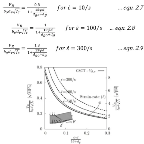
2.3.2 Material Strain Rate Effect ... 33
2.3.3 Localised punching and strain rate effect ... 35
2.3.4 Compressive membrane action... 36
2.3.5 Vierendeel Action ... 38
2.3.6 Tensile membrane action ... 39
2.3.7 Post-punching shear mechanism ... 43
2.3.8 Dynamic amplification of gravity load ... 51
2.4 Design against progressive collapse ... 52
2.4.1 Indirect design methods ... 54
2.4.2 Risk-Based methods ... 55
2.4.3 Isolation by segmentation ... 55
2.4.4 Direct design methods ... 55
2.5 Code recommendations on robustness of flat slabs ... 58
2.5.1 Load combination for accidental cases ... 58
2.5.2 Integrity reinforcement ... 59
2.6 Conclusions ... 61
... 62
Modelling of post-punching shear response of isolated slab-column specimens... 62
3.1 Introduction ... 63
3.2.1 Element formulations and constitutive models ... 65
3.2.2 Validation of numerical model against test data of symmetrical tests ... 72
3.2.3 Asymmetric post-punching shear response ... 80
3.2.4 Comparison of symmetric and asymmetric predictions from numerical models . 86 3.3 Analytical model for symmetric and asymmetric post-punching shear ... 88
3.3.1 Symmetric post-punching shear response ... 91
3.3.2 Validation of analytical model against symmetric tests ... 106
3.3.3 Comparison of results with other approaches from literature ... 110
3.3.4 Predictions using analytical approach in asymmetric cases ... 113
3.4 Conclusions ... 115
... 117
Numerical modelling of slab-column subsystem and flat slab system... 117
4.1 Introduction ... 118
4.2 Dynamic Punching ... 119
4.2.1 Existing experimental data on localized impact loading of RC slabs ... 120
4.2.2 Numerical modelling using solid finite elements ... 122
4.2.3 Combined analytical-numerical approach ... 125
4.2.4 Results of dynamic punching assessment ... 127
4.3 System modelling of flat slab structures ... 132
4.3.1 Solid-shell interface coupling ... 135
4.3.2 Flat slab case study: structural configuration and restraints ... 138
4.3.4 Numerical model of flat slab system ... 146
4.3.5 Modelling of initial local damage ... 147
4.4 Numerical results of slab system response ... 149
4.4.1 System response without integrity reinforcement ... 149
4.4.2 System response with integrity reinforcement ... 156
4.5 Conclusions ... 160
... 162
Analytical models for progressive collapse analyses ... 162
Introduction ... 163
Slab-column subsystem response ... 164
5.2.1 Demand capacity ratio of opposite column after column removal... 164
5.2.2 Increase in shear demand (∆𝑽) ... 165
5.2.3 Moment transfer and slenderness effects (∆𝑴 and ∆𝑺) ... 167
5.2.4 Column removal under constant gravity loading ... 171
5.2.5 Slab-column compatibility relationship ... 172
5.2.6 Application of the Ductility-Centred Robustness Assessment (DRA) ... 174
5.2.7 Results of application of DRA to connection subsystem ... 179
Flat slab system response ... 183
5.3.1 Deformation modes ... 183
5.3.2 Flat slab system compatibility ... 185
5.3.4 Compressive membrane action... 193
5.3.5 Results of slab system analysis with nonlinear static response ... 197
5.3.6 Verification of static nonlinear flat slab subsystem response ... 201
5.3.7 Influence of material strain rate ... 204
5.3.8 Application of the Ductility-Centred Robustness Assessment (DRA) ... 206
5.3.9 Results of analytical dynamic flat slab system response ... 209
Conclusions ... 212
... 214
Implications of proposed models towards guidance of structural robustness of flat slab structures ... 214
6.1 Introduction ... 215
6.2 Potential occurrence of punching after column removal ... 216
6.2.1 The Concrete Society (2007) ... 217
6.2.2 German Concrete and Construction Company, DBBV (2011) ... 219
6.2.3 Keyvani, Sasani and Mirzaei (2014) ... 220
6.2.4 Liu (2014) ... 222
6.2.5 Conclusion on potential occurrence of punching after column removal ... 224
6.3 Potential occurrence of progressive collapse after column removal ... 227
6.3.1 Code based formulae ... 227
6.3.2 Effectiveness of integrity reinforcement on flat slab systems ... 228
6.3.4 Conclusion on potential occurrence of progressive collapse after column removal 238
6.4 Conclusions ... 239
... 240
Conclusions and recommendations for future research ... 240
7.1 Introduction ... 241
7.2 Conclusions ... 243
7.2.1. Modelling of shear response of slab-column connections ... 243
7.2.2. Numerical modelling of flat slab system ... 244
7.2.3. Analytical models for progressive collapse analyses ... 245
7.2.4. Application of proposed analytical models to design cases ... 246
7.2.5. Recommendations for future research ... 248
References ... 250
List of figures
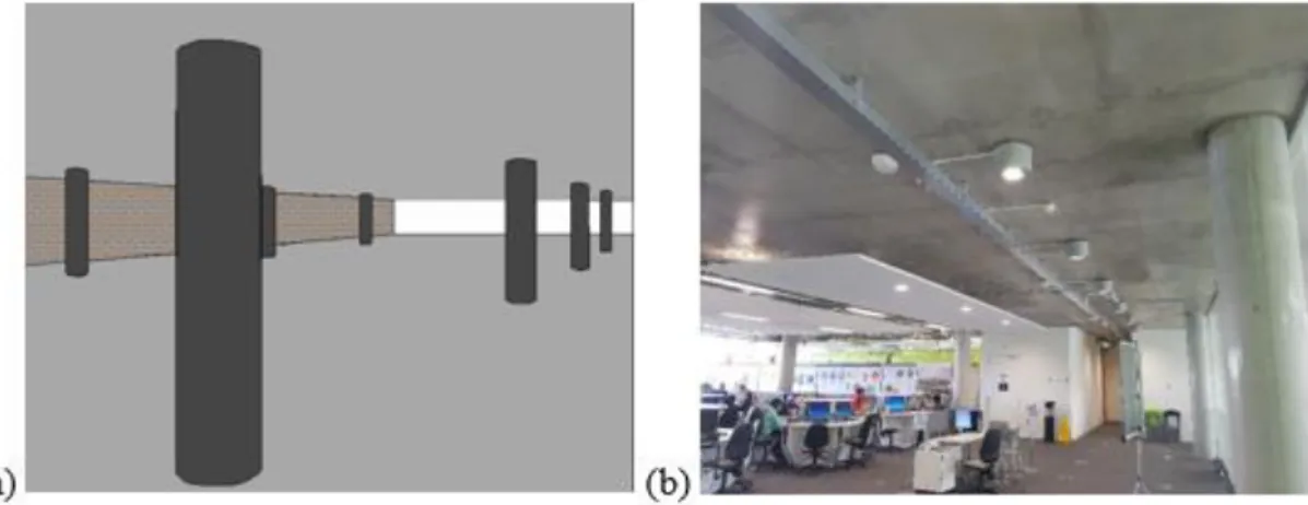
Figure 1.1: Flat slab structures: (a) structural configuration; (b) Innovation for health learning
laboratory, University of Surrey ... 4
Figure 1.2: Collapse of flat slab structures: (a) Pipers Row Car Park, Wolverhampton (Wood, 2001); (b) 2000 Commonwealth Avenue, Boston (King & Delatte, 2004) ... 5
Figure 1.3: Flat slab system and slab-column connection subsystem ... 7
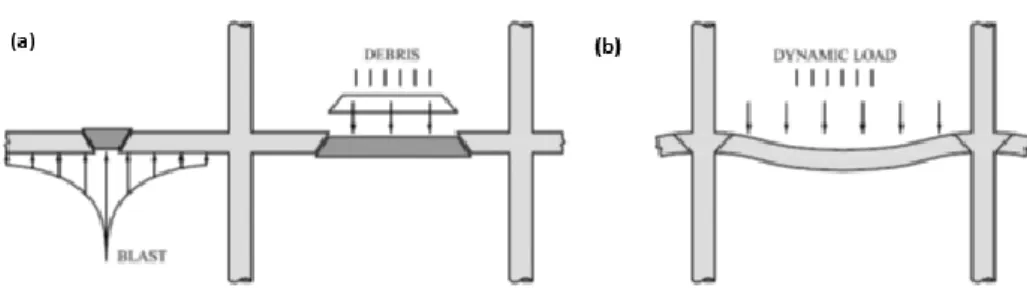
Figure 2.1: Local and global response of flat slabs (a) local impulsive failure due to blast and impact; (b) global response with possible punching shear failure of connections (Sagaseta et al., 2017) ……… ... 17
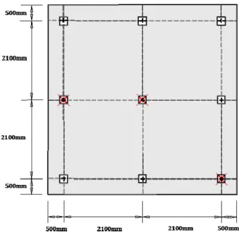
Figure 2.2: Slab specimen details (Yi et al., 2014) ... 18
Figure 2.3: Specimen details (a) corner and penultimate support removal tests (b) middle support removal test (Russell et al., 2015) ... 20
Figure 2.4: Slab specimen details (Xue et al., 2018) ... 22
Figure 2.5: Slab geometry (Keyvani et al., 2014) ... 23
Figure 2.6: Slab geometry (Liu, 2014) ... 25
Figure 2.7: Slab geometry (The Concrete Society, 2007) ... 27
Figure 2.8: Flexural, punching shear and post-punching shear response of slab-column connections ... 29
Figure 2.9: Load-deflection response of interior flat slab panel from CMA to TMA (Adapted from Mitchell and Cook, 1984) ... 29
Figure 2.10: Vierendeel action due to moment capacity in beam/column connections (Adapted from DCLG, 2011) ... 30
Figure 2.11: Classification of existing punching shear models (Koppitz et al., 2013) ... 30
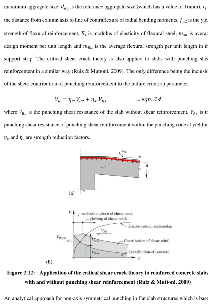
Figure 2.12: Application of the critical shear crack theory to reinforced concrete slabs with and without punching shear reinforcement (Ruiz & Muttoni, 2009) ... 32
Figure 2.13: Influence of material strain rate (a) concrete, (b) steel (fib, 2012b)... 34 Figure 2.14: Two-phase model: (a) Contact phase; (b) Post-contact phase... 35 Figure 2.15: Influence of strain-rate on punching strength according to CSCT (Muttoni, 2008; and Micallef et al., 2014) ... 36 Figure 2.16: Membrane mechanisms after interior column loss (DCLG, 2011) ... 40 Figure 2.17: Calculated membrane forces to resist gravity load; (a) Punching shear capacity (b) Tensile membrane capacity (Sagaseta et al., 2017) ... 43 Figure 2.18: Post-punching shear ... 44 Figure 2.19: Horizontal projection of conical surfaces ... 46 Figure 2.20: Progressive destruction of concrete during post-punching (adapted from Mirzaei, 2010) ……… ... 47 Figure 2.21: Comparison of nonlinear static and pseudo-static (dynamic) response (Izzuddin et al., 2008) ….. ... 57 Figure 3.1: Eight node solid hexahedron element and two node beam element ... 66 Figure 3.2: (a) Finite element meshing for slab specimen PM12 (b) Explicit modelling of reinforcements for slab specimen PM12 ... 67 Figure 3.3: (a) Winfrith concrete material model verification in compression and tension
(Schwer, 2010), (b) Elastic-plastic behaviour with kinematic and isotropic hardening (LSTC, 2014a) …… ... 69 Figure 3.4: Expected coupling points for Lagrangian element in ALE elements. ... 71 Figure 3.5: Bond stress-slip test (a) P0 test characteristics (Malvar, 1992) (b) Mesh
discretization for P0 FE model (c) Bond stress-slip relationships (and bond stress –bar
displacement in the FEA). ... 72 Figure 3.6: A typical isolated slab specimen: simply supported with concentric loading ... 73
Figure 3.7: Comparison of strength parameters with varying values erosion parameter (Test
PM12) ... 77
Figure 3.8: Comparison of strength parameters with varying values of element depth to slab depth ratio (Test PM12) ... 77
Figure 3.9: Comparison of strength parameters with varying values of element length (Test PM4) ... 77
Figure 3.10: Symmetric: Load displacement curve (PS: Punching shear, PPS: Peak post-punching shear and RSS: Residual shear strength after post-punching) ... 79
Figure 3.11: Comparison of damage at displacement of 98mm for the SS specimen: (a) Test specimen (b) F.E simulation ………. ... 81
Figure 3.12: (a) Evolution of slab rotation up until and just after punching shear failure ... (b) Observed kinematics before and after punching from FE models ……… ... 81
Figure 3.13: Slab displacement contour after complete failure of columns 2 and 3 (displacement in metres) ... 84
Figure 3.14: Slab displacement around column 2 ... 84
Figure 3.15: Displacement ratios at load step 11 after complete failure of adjacent connections ... 84
Figure 3.16: Displacement ratios for opposite face at various analysis steps ... 84
Figure 3.17: Derivation of displacement factors from plastic deformations (a) Column 1-2-3 (b) Column 2-4 ……….. ... 85
Figure 3.18: Development of punching shear failure in asymmetric case ... 87
Figure 3.19: Asymmetric and symmetric PM4: Load displacement curve ... 87
Figure 3.20: Asymmetric and symmetric PM12: Load displacement curve ... 87
Figure 3.22: Activation and deactivation of flexural reinforcement. ... 89
Figure 3.23: Basic concrete breakage model parameters ... 92
Figure 3.24: Geometric assumptions in proposed analytical modelling of post-punching shear mechanism … ... 93
Figure 3.25: Slab dilatancy from FE models ... 94
Figure 3.26: Capacity of each deformation mode during progression of post-punching ... 94
Figure 3.27: Basis of analytical modelling of progression of concrete breakage ... 95
Figure 3.28: Responses of embedded rebar (a) flexural (b) membrane ... 99
Figure 3.29: Monotonic stress-strain curve for steel reinforcement bars ... 100
Figure 3.30: Definition of cover parameters ... 101
Figure 3.31: Displacement of reference point at punching shear failure ... 103
Figure 3.32: Flow chart for analytical determination of post-punching load-displacement response; (a) Flexural reinforcement (b) Integrity reinforcement ... 106
Figure 3.33: Verification of analytical post-punching shear model, with (a) to (k) representing individual test specimens analysed as stated in the respective Figures ... 109
Figure 3.34: (a) Comparison of strain in flexural reinforcements obtained through test, analytical and F.E modelling of post-punching shear of test specimen SS (Habibi, 2012); (b) Comparison of axial stress in flexural reinforcements obtained through analytical and F.E modelling of post-punching shear of test specimen SS ... 110
Figure 3.35: (a) Comparison of strain in integrity reinforcements obtained through analytical and F.E modelling of post-punching shear of test specimen SS (Habibi, 2012); .. (b) Comparison of axial stress in integrity reinforcements obtained through analytical and F.E modelling of post-punching shear of test specimen SS ... 110
Figure 3.36: Comparison of post punching shear responses obtained through tests, proposed analytical model, analytical model of Mirzaei (2010) and (Habibi et al., 2014) ... 113
Figure 3.37: Asymmetric PM4: Load displacement curve- Analytical ... 114
Figure 3.38: Asymmetric PM12: Load displacement curve- Analytical ... 114
Figure 4.1: Local vs. global response: (a) punching of the slab during local impulsive behaviour; (b) punching of the column-slab connection at peak dynamic response; and (c) influence of slab rotation and strain-rate on punching strength according to CSCT (Muttoni, 2009; and Micallef et al., 2014) ... 120
Figure 4.2: Slab physical characteristics: (a) Tests (dimensions in mm), (b) Typical FE model of slab specimens (10F-a)………… ... 124
Figure 4.3: Moments on activation of higher deformation mode (Ulaeto & Sagaseta, 2017a) 126 Figure 4.4: Local damage on Slab No.3 (a) top face (Chen & May, 2009), (b) bottom face (Chen & May, 2009), (c) top face (F.E), (d) bottom face (F.E) ... 128
Figure 4.5: Numerical prediction of dynamic punching shear failure: (a) Failure in slab specimen 10F-a, (b) No failure in slab specimen 20F-e ... 128
Figure 4.6: Dynamic equilibrium in slab TH2... 129
Figure 4.7: Comparison of displacement-time response (a) TH2 (b) TH6 (c) TH7 ... 130
Figure 4.8: Slab displaced shapes at peak positive and negative displacement (TH2) ... 131
Figure 4.9: Determination of rso based on points of contra-flexure of moments: (a) TH2 (b) Test No.3 …. ... 132
Figure 4.10: Dynamic punching shear failure assessment: (a) TH2 (Hrynyk and Vecchio, 2014) (b) Test No.3 (Chen & May, 2009) ... 132
Figure 4.11: (a) Quarter Flat slab system model using solid and shell elements (b) Section through connection region……… ... 134
Figure 4.12: Solid-shell interface ... 136 Figure 4.13: Comparison of an isolated slab specimen PM4 (Ruiz et al., 2013) with and
(c) flexural, punching shear and post-punching response (d) damage contour of punching shear
failure from FE model ... 138
Figure 4.14: Model of continuous flat slab system ... 139
Figure 4.15: (a) Steel reinforcement detail for slab; (b) Response of column-slab connection (modelled as isolated slab)…… ... 143
Figure 4.16: Finite element mesh discretization: ... (a) Explicitly modelled connection region using solid elements; (b) Entire flat slab model using solid and shell elements ... 147
Figure 4.17: Progressive collapse of slab system with frequent load combination ... 150
Figure 4.18: Displacement-time curve at point of column removal under different levels of gravity loading (frequent, quasi-permanent and permanent) ... 151
Figure 4.19: Gravity load redistribution over time for frequent load case: (a) all connections (b) connections A2 and B2 ………. ... 152
Figure 4.20: Average x-stresses in solid elements in 1st slab strip (frequent load case) ... 154
Figure 4.21: Top and bottom reinforcement of 1st strip (frequent load case): (a) axial force, (b) axial stress ….. ... 154
Figure 4.22: Location of slab strips ... 154
Figure 4.23: Membrane force contribution of slab strips (frequent load case) ... 156
Figure 4.24: Membrane force developed in slab without integrity reinforcement (frequent load case) ……….. ... 156
Figure 4.25: Progressive collapse arrest as observed with displacement time curves: (a) models with integrity reinforcement but different load cases; (b) models with frequent load case but with and without integrity reinforcement … ... 157
Figure 4.26: Connection vertical reaction at A2 and B2 (frequent load case) ... 158
Figure 4.27: Gravity load redistribution ... 159
Figure 4.29: Membrane force developed in slab with integrity reinforcement (frequent load case) ……….. ... 160 Figure 4.30: Axial force in reinforcements in 1st strip ... 160 Figure 5.1: Geometric response of slab (a) load distribution and redistribution, (b) displacement profile, and (c) Influence of column removal on static reaction in rectangular column layouts (Sagaseta, Ulaeto and Russell, 2017) ………….. ... 166 Figure 5.2: Influence of 𝑟𝑠𝑑 on slab-column load rotation response ... 168 Figure 5.3: Influence of 𝑘𝑒 on punching failure-criterion (CSCT) ... 168 Figure 5.4: Influence of column removal on distribution of shear forces along control perimeter at 0.5d from column face for Ly/Lx= 1.5 according to shear field analysis (Sagaseta, Ulaeto and
Russell, 2017) ... 168 Figure 5.5: Change in connection stiffness after column removal at gravity loading with
induced shear 𝑉0 ... 172 Figure 5.6: Shear demand vs. slab rotation in a column removal case with quasi-static load (Olmati et al., 2017) ... 172 Figure 5.7: Slab rotation at distances from column centre (Tassinari, 2011) ... 173 Figure 5.8: Single degree of freedom approximation ... 174 Figure 5.9: Pseudo-static response based on the DRA approach (B. A. Izzuddin et al., 2007)- (a) linear elastic response; and (b) proposed parabolic-plastic response ... 176 Figure 5.10: Relationship between static and dynamic response after column removal ... 177 Figure 5.11: Proposed approach for punching assessment of sudden column removal based on the CSCT and pseudo-static response from DRA ... 178 Figure 5.12: Flow chart for proposed simplified analytical assessment of punching adjoining column after sudden removal of interior column ... 179
Figure 5.13: Application of proposed DRA approach to connection subsystem (a) 𝑔𝑘
(permanent) (b) 𝑔𝑘 + 𝜓2𝑞𝑘 (quasi-permanent) (c) 𝑔𝑘 + 𝜓1𝑞𝑘 (frequent) ... 182 Figure 5.14: Deformation modes at stages of horizontal failure propagation (Quarter flat slab system model) ……….. ... 184 Figure 5.15: Moments and deformations in a continous slab element at development of a flexural plateau (Jurgen Einpaul, 2016) ... 186 Figure 5.16: Relationship between 𝜍 and 𝜌ℎ𝑜𝑔𝜌𝑠𝑎𝑔 ... 188 Figure 5.17: Relationship between 𝜍 and 𝑓 ... 188 Figure 5.18: Comparison between numerical prediction of displacement at the mid-span and Equation 5.15 ……….. ... 189 Figure 5.19: Comparison between test prediction of displacement at the mid-span and
Equation 5.15 ... 190 Figure 5.20: Post-punching response of continuous flat slab connection ... 191 Figure 5.21: Two-dimensional finite element model of flat slab ... 194 Figure 5.22: Comparison of compressive membrane action (a) due to flexural cracking in slab around columns; (b) due to force mechanism developed at small deflections ... 196 Figure 5.23: Punching shear strength prediction with consideration of CMA ... 197 Figure 5.24: Influence of compressive membrane action on opposite connection response: (a) without integrity reinforcement, (b) with integrity reinforcement (2# 25mm 𝜙 bars in each orthogonal direction) ... 198 Figure 5.25: Estimation of 𝑃 from 𝑉 ... 199 Figure 5.26: Relationship between opposite and adjacent connection responses: (a) without integrity reinforcement, (b) with integrity reinforcement (2# 25mm 𝜙 bars in each orthogonal direction) …… ... 199
Figure 5.27: Flat slab system load-displacement relationship: (a) Without integrity
reinforcement total vertical load; (b) With integrity reinforcement total vertical load ... 200
Figure 5.28: Ratio of vertical reaction in adjacent connection to that in opposite connection obtained from F.E simulation ………. ... 202
Figure 5.29: Vertical reactions at opposite and adjacent connections: (a) Slab system without integrity reinforcement; (b) Slab system with integrity reinforcement ... 202
Figure 5.30: Vertical connection reaction forces for slab without integrity reinforcement .... 203
Figure 5.31: Vertical connection reaction forces for slab with integrity reinforcement ... 203
Figure 5.32: Influence of strain rate on punching shear strength at opposite connection after column removal ……….. ... 206
Figure 5.33: Responses over elastic and plastic phases (Adapted from Izzuddin and Nethercot, 2009)……….. ... 207
Figure 5.34: Gravity load distribution at three phases of response after removal of internal column …….. ... 208
Figure 5.35: Calculation process for flat slab system assessment ... 210
Figure 5.36: System non-linear static and pseudo-static response without integrity reinforcement ... 212
Figure 5.37: System non-linear static and pseudo-static response with integrity reinforcement ……… ... 212
Figure 6.1: Slab geometry (The Concrete Society, 2007) ... 218
Figure 6.2: Response of connection B2 according to the proposed method ... 218
Figure 6.3: Slab geometry (DBBV, 2011) ... 219
Figure 6.4: Response of opposite connection according to the proposed method ... 219
Figure 6.6: Response of opposite connections according to the proposed method (a) C3 (b) B2 ……… ... 222 Figure 6.7: Slab geometry ( Liu, 2014) ... 223 Figure 6.8: Response of opposite connections according to the proposed method ... 223 Figure 6.9: Influence of punching shear reinforcement (12 legs of 10mm bars) on connection response after sudden column removal (a) C3 (Keyvani et al., 2014) (b) B2 (Keyvani et al., 2014) (c) Opposite connection (Liu, 2014)………….. ... 226 Figure 6.10: Symmetric and asymmetric post-punching shear response of the opposite
connection with integrity reinforcement ... 230 Figure 6.11: Breakage of concrete over integrity reinforcement ... 231 Figure 6.12: Flat slab system deformation mode 1 ... 232 Figure 6.13: Static and pseudo-static response of flat slab system with different areas of
integrity reinforcement …. ... 234 Figure 6.14: Maximum axial stress in integrity reinforcement at the critical face of connection after sudden column removal under frequent loading in dynamic finite element analysis
List of tables
Table 2.1: Definitions of Progressive Collapse ... 15 Table 3.1:Characteristics and material properties of isolated slab specimens adopted from Mirzaei (2010), Habibi (2012), Melo and Regan (1998) and Peng (2015). ... 74 Table 3.2: Comparison of proposed post-punching model to existing models ... 90 Table 4.1: Specimen and material details ... 123 Table 4.2: Slab physical characteristics and material properties ... 140 Table 4.3: Design results and slab strength characteristics ... 140 Table 4.4: Area of designed integrity reinforcements ... 145 Table 5.1: Properties of flat slab models ... 174 Table 5.2: Opposite connection response characteristics ... 180 Table 6.1: Gravity loading for nonlinear static residual capacity assessment... 215 Table 6.2: 𝑫𝑹𝟎 of connections assessed... 224 Table 6.3: Prediction of post-punching shear resistance using code formulae ... 228 Table 6.4: Required area of post-punching shear reinforcement ... 229 Table 6.5: Required area of integrity reinforcement for sudden column removal scenario .... 238
List of symbols
Latin upper case letters𝐴5 Steel rebar yield stress at the required strain rate, ε̇
𝐴5.1 Steel rebar ultimate strain at a quasi-static strain rate with value of 5x10⁻⁵ s-1
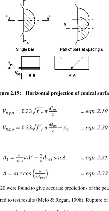
𝐴𝑐ℎ Area of the horizontal projection of the conical surface
𝐴𝑑 Accidental actions
𝐴𝑠 Required area of steel reinforcement
𝐴𝑠.𝑖𝑛𝑡. Required area of integrity reinforcement for symmetric cases
𝐴𝑠.𝑖𝑛𝑡.𝐶.𝑅 Required area of integrity reinforcement for cases of loss of internal column
𝐴𝑠𝑤 Total area of punching shear reinforcement provided
𝐷𝑅 Demand-capacity ratio
𝐷𝑅0 Demand capacity ratio prior to the sudden removal of the internal connection
𝐸𝑠 Modulus of elasticity of flexural steel
𝐸𝑠ℎ Tangential modulus at initial strain hardening
𝐺𝑘 Characteristic permanent loads (KN)
𝐼𝑠 Second moment of area of steel rebar
𝑃 Column reaction force
𝑃𝑑𝑦𝑛 Static equivalent of the dynamic reaction
𝑃𝑙𝑖𝑚 Limit of static gravity load where significant plastic response of the connection does not occur
𝑃𝑙𝑖𝑚.𝑝𝑠 Limit of pseudo-static load where significant plastic response of the connection does not occur
𝑃𝑠𝑡𝑎𝑡 Static reaction force
𝑄𝑘 Characteristic variable loads (KN)
𝑅𝑒 Steel rebar ultimate strain at the required strain rate, ε̇
𝑅𝑒1 Steel rebar yield stress at a quasi-static strain rate with value of 5x10⁻⁵ s-1
𝑅𝑚 Steel rebar tensile strength at the required strain rate, ε̇
𝑅𝑚1 Steel rebar tensile strength at a quasi-static strain rate with value of 5x10⁻⁵ s-1
𝑉𝑐𝑜𝑛.𝑏𝑟𝑒𝑎𝑘 Shear strength developed from breaking of concrete within the punching shear cone
𝑉𝑐𝑜𝑛.𝑠𝑝𝑎𝑙𝑙 Shear strength developed from breakage of concrete outside the punching shear cone
𝑉𝑑𝑦𝑛 Dynamic shear demand
𝑉𝑓𝑙𝑒𝑥 Connection flexural strength
𝑉𝑅 Shear strength
𝑉𝑅𝑐 Punching shear resistance of the slab without shear reinforcement
𝑉𝑅𝑠 Punching shear resistance of punching shear reinforcement within the punching cone at yielding
Latin lower case letters
𝑏0 Shear resisting control perimeter
𝑏𝑓𝑙𝑒𝑥 Width of each side of the punching cone
𝑏𝑠 Width of the support strip
𝑏𝑢 Diameter of the circle with the same area as the region inside the basic control perimeter
𝑐 Column width
𝑐1 Nominal cover
𝑑 Effective depth of the slab
𝑑𝑔 Maximum aggregate size
𝑑𝑔0 Reference aggregate size (which has a value of 16mm)
𝑑𝑟𝑒𝑠 Depth of concrete above steel rebars
𝑒𝑢 Eccentricity of the resultant shear force with respect to the centroid of the basic control perimeter
𝑓 Ratio of the shear load to the flexural capacity of the slab
𝑓𝑐 Compressive strength of concrete
𝑓𝑐𝑘 Characteristic cylinder strength of concrete in compression
𝑓𝑐𝑚 Mean cylinder value of compressive strength
𝑓𝑐𝑡 Tensile strength of concrete
𝑓𝑐𝑡.𝑒𝑓𝑓 Effective tensile strength in concrete
𝑓𝑐𝑡𝑚 Mean value of concrete tensile strength
𝑓𝑠 Stress in steel rebar
𝑓𝑠ℎ Stress at strain hardening
𝑓𝑠𝑡𝑚 Estimated stress developed in rebar due to bond
𝑓𝑦 Yield stress
𝑓𝑦𝑑 Yield strength of flexural reinforcement
𝑓𝑦𝑘 Characteristic yield strength of steel
𝑔𝑘 Characteristic permanent action (KNm-2)
𝑘𝑒 Reduction factor for the control perimeter in the presence of column to slab moments and shear stress field concentrations
𝑙𝑑𝑖𝑙 Dilatancy length of slab
𝑙𝑒𝑓𝑓 Reduced effective span developed at higher deformation modes primarily due to inertia effects
𝑙𝑥 Slab span in the x orthogonal direction
𝑙𝑦 Slab span in the y orthogonal direction
𝑚𝑐𝑟 Cracking moment per unit width of slab
𝑚𝐸𝑑 Average design moment per unit length
𝑚𝑅.ℎ𝑜𝑔 Hogging moment per unit slab width
𝑚𝑅.𝑠𝑎𝑔 Sagging moment per unit slab width
𝑚𝑅𝑑 Average flexural strength per unit length in the support strip
𝑛 Number of bars
𝑛𝑏𝑟𝑒𝑎𝑘 Total number of activated flexural reinforcement contributing to the post-punching resistance
𝑝𝑖 Distance of progression of breakage of punching shear cone towards column
𝑞𝑖 Distance of progression of spalling (or breakage) of concrete in slab away from the column
𝑞𝑘 Characteristic permanent action (KNm-2)
𝑞𝑘 Characteristic variable loads (KNm-2)
𝑟𝑠 Distance from the support to the point of zero radial moment
𝑠 Reinforcement bar spacing
𝑣𝑝𝑒𝑟𝑝,𝑑,𝑚𝑎𝑥 Maximum value of the projection of shear force perpendicular to the basic control
perimeter
𝑤 Displacement
𝑤𝑎𝑑𝑗 Slab displacement close to the column at the side adjacent to that of the removed column
𝑤𝑐𝑟𝑖𝑡 Slab displacement close to the column at the side of the removed column
𝑤𝑐𝑡𝑟 Slab displacement at the point the internal column is removed
𝑤𝑐𝑡𝑟.𝑎𝑑𝑗 Slab displacement at the connection adjacent to that where internal column is removed
𝑤𝑐𝑡𝑟.𝑑𝑦𝑛 Slab displacement at the point the internal column is removed suddenly
𝑤𝑐𝑡𝑟.𝑜𝑝𝑝 Slab displacement at the connection opposite to that where internal column is removed
𝑤𝑓𝑙𝑒𝑥 End-to-end displacement of rebar over the post-punching transfer zone, during flexural phase of post-punching shear response
𝑤𝑜𝑝𝑝 Slab displacement close to the column at the side opposite to that of the removed column
𝑤𝑝.𝑐𝑟𝑖𝑡, Slab displacement close to the column at the side of the removed column at punching
𝑤𝑝𝑝,𝑐𝑟𝑖𝑡, Slab displacement close to the column at the side of the removed column at post-punching
𝑤𝑡ℎ Width of the critical crack
𝑧 Curvature influenced zone for the length of reinforcement embedded in concrete
Greek upper case letters
∆𝑉 Increase demand ratio of static shear force at the adjacent column after sudden column removal
∆𝑆 Slenderness factor
∆𝑀.𝑝𝑝 Factor due to geometric and load asymmetry
∆𝑀 Moment transfer factor
∆𝑉.𝑝𝑝 Peak possible increase in load (during post-punching) after column removal of an internal bay with regular layout and equal spans in both directions
Greek lower case letters
𝛾 Inclination of the concrete breakage cone with the horizontal
𝛾𝑐 Partial factor for concrete for the ultimate limit states
𝛾𝑠 Partial factor for steel for the ultimate limit states
𝛿𝑎𝑑𝑗 Horizontal distance from the opposite column to a point close to the column on the adjacent side
𝛿𝑐𝑟𝑖𝑡 Horizontal distance from the opposite column to a point close to the column on the critical side
𝛿𝑜𝑝𝑝 Horizontal distance from the opposite column to a point close to the column on the opposite side
𝛿𝑤 Increment in slab displacement
𝜀𝑠 Strain in steel rebar
𝜀𝑠.𝑓−𝑚 Maximum strain in rebar during flexural phase of post-punching response
𝜀𝑠ℎ Strain at onset of strain hardening
𝜀𝑠𝑢 Strain at peak stress
𝜀𝑦 Yield strain
𝜀̇ Strain rate
𝜀1̇ Steel rebar quasi-static strain rate with a value of 5x10⁻⁵ s-1
𝜀𝑐̇ Strain rate for concrete in compression
𝜀𝑐𝑡̇ Strain rate for concrete in tension
𝜀𝑐𝑡𝑜̇ Concrete quasi-static strain rate in tension with a value of 1x10⁻⁶ s-1
𝜍 Compatibility constant
𝜂 Uniform gravity area load
𝜂𝑐 Strength reduction factors for concrete in punching
𝜂𝑅 Ratio between sagging and hogging moment capacities
𝜂𝑠 Strength reduction factors for steel reinforcement in punching
𝜃 Angle of inclination of punching shear cone with the horizontal
𝜆𝑑 Dynamic load amplification factor
𝜆𝑑.𝑝𝑝 Dynamic load amplification factor for post-punching
𝜆𝑤 Displacement amplification factor
𝜌𝑠𝑝𝑎𝑛 Flexural reinforcement provided at span
𝜌𝑠𝑢𝑝𝑝𝑜𝑟𝑡 Flexural reinforcement provided at support
𝜙 Diameter of reinforcing steel bar
𝜒𝑟 Radial curvature of slab
𝜓 Slab rotation at a distance close to the column
𝜓1 Reduction factor for frequent values of variable action
𝜓2 Reduction factor for quasi-permanent values of variable action
𝜓𝑓𝑙𝑒𝑥 Maximum rotation of rebar during flexural phase of post-punching shear response
𝜓𝑚𝑒𝑚. Steel rebar rotation at membrane phase of post-punching
𝜓𝑝𝑠 Pseudo-static rotation
𝜓𝑠𝑐 Rotation close to the connection for a self-confined slab
𝜓𝑠−𝑐 Slab rotation at a distance close to the column, with considerations of compressive membrane action
List of publications and conference proceedings
PublicationsUlaeto, N. and Sagaseta, J. (2017). Numerical and analytical modelling of localized impact load in RC panels, FABIG Newsletter, (70), pp. 56–63. (Reviewed and published)
Sagaseta, J., Ulaeto, N. and Russell, J. (2017). Structural robustness of concrete flat slab structures, American Concrete Institute Special Publication (SP), vol. 315, and Federal Internationale du Beton (fib) bulletin, 81, pp. 273-298. (Reviewed and published)
Sagaseta, J. and Ulaeto, N. (2018). Discussions from the March 2018 ACI Structural Journal: Behavior of reinforced concrete slabs under low-velocity impact by Xiao, Y., Li, B. and Fujikake, K., ACI Structural Journal, 115(2), pp. 559–562. (Reviewed and published)
Ulaeto, N. and Sagaseta, J. (2019). A post-punching shear model for column-slab connections for progressive collapse analyses. (In preparation).
Ulaeto, N. and Sagaseta, J. (2019). Punching of internal columns in flat slab structures due to sudden loss of near column. (In preparation).
Ulaeto, N. and Sagaseta, J. (2019). A model for progressive collapse analysis of concrete flat slab structures. (In preparation).
Conference proceedings
Ulaeto, N. and Sagaseta, J. (2017b) ‘Numerical modelling of symmetric and asymmetric punching and post-punching shear responses of RC flat slabs’, Proceeding of the 11th European LS-DYNA Conference. Salzburg. (Reviewed and published).
1.1
Motivation for the study
In buildings and civil engineering structures, initial local failure can result from the use of inappropriate material or system models, error in construction or excessive loading. They also can result from malevolent or accidental actions such as vehicle, ship or airplane impact; explosions resulting from gas leaks, terrorist attack; or impact and explosion from missile attacks. Environmental actions such as flooding, extreme wind or fire may also lead to local damage. A partial or total redistribution of loads in the structure will result after the occurrence of an initial local failure as the structure tries to reach a new state of equilibrium, relative to its new loading and support conditions. Failure of adjoining structural elements and connections will result if their load and deformation capacities are insufficient in this new state. Progression of damage up to a point where a state of equilibrium is satisfied is commonly referred to as progressive collapse (Mirzaei, 2010). If there exists a disproportion between the initial triggering event and the final state of the structure which violates defined performance objectives, a disproportionate collapse is said to have occurred (Starossek, 2009; DCLG, 2011). The insensitivity of building and civil engineering structures to initial local failure is a characteristic commonly referred to as structural robustness. It is a property, designers aim to incorporate into structures so as to minimize secondary structural damages (which can lead to progressive collapse) and other consequential losses which could result from an initial local damage triggering event.
Interest in the avoidance of disproportionate collapse sprung in the UK after a gas explosion in a single kitchen triggered the progressive collapse of the 22-storey Ronan Point tower in 1968. Interest rouse again after the Alfred P. Murrah Building Oklahoma in 1995 and the September 2001 attack on the World Trade Centre. Both cases of collapse after malevolent actions drew global attention to the need for considerations of robustness of new and existing structures. Design codes and building regulations laid more emphasis on improving robustness of important
and high risk structures. Due to this globally renewed interest in structural robustness, researches over the past 20 years have led to breakthroughs in knowledge relating to the design and construction of robust structures.
Mechanisms developed during progressive collapse are dependent on the type of structural system and the initiating event. This is because some failure mechanisms are peculiar to certain type of structures, the structural element which failed initially, and the level of dynamic load imposed on the structure globally and locally. Though significant amount of research has been carried out in the last 20 years in the area of progressive collapse, most of these focus on two-dimensional frame trusses (Yan, Zhao and Lu, 2017; Li, Li, Jiang and Lu, 2018a; and Li, Li, Jiang and Lu, 2018b); space frames structures (Xu, Han, Parke and Liu, 2017); steel and reinforced concrete beam-column framed structures (Vlassis, Izzuddin, Elghazouli and Nethercot, 2008; Szyniszewski and Krauthammer, 2012; and Sasani, Bazan and Sagiroglu, 2007). These studies have covered experimental, numerical and analytical work aimed at understanding and predicting, using simple tools, the behavior of structures after an initial local failure. However, gaps still exist in knowledge on other forms of construction which are widely used in practice such as reinforced concrete flat slab structures (Mirzaei, 2010). This due to the peculiar nature of mechanisms developed at slab-column connections and their sensitivity of dynamic loading.
Figure 1.1: Flat slab structures: (a) structural configuration; (b) Innovation for health learning laboratory, University of Surrey
Flat slabs are reinforced concrete slabs supported directly on columns without beams (Figure 1.1). Advantages obtained from their incorporation into structures include ease of construction, reduced story height and ease of routing of services. Hence, they are commonly applied in the construction of medium-rise office buildings and car parking structures. The behavior of flat slab structures before and after initial local failure is quite different from those of conventional reinforced concrete frame structures. Unlike conventional reinforced concrete framed structures where beams are primarily relied on for transfer of shear forces and moments from slabs to columns, flat slab structures rely on the slab-column connections. Load concentrations can be significant at edge and corner columns as well as around internal columns.
The critical design mode of failure for flat slab structures (ultimate limit state) is generally punching shear at the slab-column connections. This type of failure is brittle, with no warning and very little deflection. To improve the strength of connections as well as ensure a ductile failure, punching shear reinforcement (vertical reinforcement provided over the depth of the slab) is introduced in the slab around the column. Most occurrences of progressive collapse in flat slab structures reported in the past have had punching as an initial local failure (Wood, 2001; Park, 2012; and King and Delatte, 2004). Some of these collapses progressed horizontally through
punching of adjoining connections due to gravity load redistribution, dynamic effects and excessive slab deformation (Wood, 2001; Park, 2012; and King and Delatte, 2004). In many cases, failure also progressed vertically due to impact of falling slabs on lower lying ones. However, in some cases such as the partial collapse of the Pipers Row Car Park at Wolverhampton in 1997 (Figure 1.2.a), punching shear failure at one column led to the punching shear failure of eight adjacent columns (Wood, 2001) with no vertical propagation of failure. Punching shear failure of a connection at the roof slab of a 16- story apartment building (Figure 1.2b) in Boston in 1971, led to the progressive collapse of all floor slabs below it (King & Delatte, 2004). Other cases of progressive collapse of flat slab structures include collapse of the 26 story Skyline Plaza apartment building in Virginia (1973), flat slab building in Bluche Switzerland (1981), 5 story Harbor Cay Condominium in Florida (1981), Gretzenbach under-ground parking garage in Switzerland (2004) and the 5 story Sampoong Departmental Store in Seoul (1995). Of the various cases of progressive collapse involving flat slab structures, Seoul’s Sampoong Departmental Store disaster is the most fatal. It resulted in 502 recorded deaths, 6 missing persons, 937 persons injured and damage to property worth KRW 100billion (Park, 2012). This shows that, though progressive collapse is a relatively rare event, its consequences could range from the multi-million loss worth of property, to very high casualty figures.
Figure 1.2: Collapse of flat slab structures: (a) Pipers Row Car Park, Wolverhampton (Wood, 2001); (b) 2000 Commonwealth Avenue, Boston (King & Delatte, 2004)
1.2
Research problem
Having emphasized that progressive collapse mechanisms are structural system dependent, design procedures specified in codes and building regulations to prevent progressive collapse lack general applicability. Though direct design rules are adaptable to different structural systems due to their thorough approach, prescriptive rules (vertical, horizontal and peripheral ties) available in most codes, such as the BS EN 1992-1-1 (CEN, 2014b), are well suited to beam-column framed systems where catenary action is a required post-initial local failure load transfer mechanism. They are not suitable for application to flat slab structures due to the development of other failure mechanisms, such as punching shear, at small deformations and spalling of flexural reinforcements around the connection during post-punching. Such mechanisms would impede development of tying mechanism required to establish an alternative load path after an initial local failure, having applied prescriptive rules (Sagaseta, Ulaeto, & Russell, 2017). This is because formation of a punching shear cone limits the number of reinforcement which should contribute to tensile membrane mechanism at the connection. Spalling and breakage of concrete around reinforcement connecting the slab to the punching shear cone after punching also limits the ability of the connection to contribute to tensile membrane action.
Over the past few decades numerical and theoretical approaches have been developed which aim at providing approaches for the assessment of progressive collapse of flat slab structures. However, there exists no numerical or theoretical approach for the assessment of response of flat slab structures which adequately incorporates the various mechanisms initiated after a local failure. Possible mechanisms initiated include flexure, punching shear, post-punching shear, vierendeel, compressive and tensile membrane actions. Transition of connection response from flexure with compressive membrane action (CMA) to punching shear and then post-punching with tensile membrane action (TMA) occurs over very small time intervals. This makes progressive collapse of flat slabs a problem involving dynamic effects, which could arise due to
the accidental event or after the initial local failure. Assessments of progressive collapse are also carried out at the post-initial local failure stage, when the structure must have under gone large deformations. Hence, they involve both material and geometric non-linearities. Existing approaches fail to adequately take into consideration post-punching mechanism, dynamic loading and its effects on the structure.
Experimental, numerical and analytical studies have been carried out which assess individual mechanisms (Sacramento, Ferreira, Oliveira and Melo, 2012; Muttoni, 2009; Lips, Ruiz and Muttoni, 2012; and Polak, 2005), providing further understanding on their response, factors influencing their response as well as providing numerical and analytical methods capable of predicting them. These studies have been based on isolated slab specimens (slab-column connection sub-system) which are representations of the area of slab around the supporting column (Figure 1.3). The isolated slab specimen considers a slab area taken from the elastic line of contraflexion (which has been established to be at a distance of 0.22𝑙 from the column centre) to the column (Muttoni, 2008).
For a system level response, it is important to understand interactions between these mechanisms. Models without one or more of these mechanisms may either give overly conservative or unsafe predictions of response of the subsystem or system response of the structure assessed. Some experimental studies have been conducted to assess response of scaled flat slab systems after column removal (Yi, Zhang and Kunnath, 2014; and Russell, Owen and Hajirasouliha, 2015). These tests aim to depict the response of flat slab structures after an initial local failure. However, limitations on specimen sizes, connection modelling as well as instrumentation, make it difficult to assess and measure mechanisms applicable to real structures. Details on these experimental studies and their contributions are elaborated in Section 2.24 of this thesis.
Application of finite element analysis (FEA) in studies on response of flat slab systems (Liu, 2014; and Olmati, Sagaseta, Cormie and Jones, 2017) have provided adequate prediction of responses up to the punching shear failure of a connection. In these studies, column removal scenario was adopted to simulate an initial local damage. The flat slab systems were modeled using shell finite elements, with punching shear failure determined at the connections using the failure criterion of the critical shear crack theory (CSCT) (Muttoni, 2008). Use of two dimensional FEA fails to adequately predict the contributions of post-punching shear and tensile membrane action beyond the punching shear failure of the first connections after column removal. These mechanisms are important in robustness considerations of flat slab structures. Hence, there is a need for numerical and analytical methods capable of predicting responses of flat slab structures at various levels of structural idealization. Simple formulae developed could be applied in design codes for guidance towards structural robustness of flat slab structures.
1.3
Aim and objectives
This research is aimed at developing novel analytical and numerical methods for progressive collapse analysis of reinforced concrete flat slab structures with a view to improving structural
robustness and the overall safety of such structures against loads experienced due to malevolent and accidental events.
For realization of the stated aim, the following objectives will be achieved:
i. Identify failure and post-failure mechanisms in flat slab structures, assess suitability of analytical and numerical methods available for their accurate prediction and their contributions to structural robustness in flat slab structures.
ii. Develop and validate numerical quasi-static assessment approaches for the determination of slab-column connection response; taking into consideration flexural, punching shear, post-punching shear and membrane responses in both isolated slab specimens and continuous flat slab systems. The methods to be developed would contribute to;
• understanding and prediction of slab-column connection responses under both symmetric and asymmetric loading and support conditions,
• and understanding of the interaction among the various mechanisms under both symmetric and asymmetric loading at a connection sub-system level. iii. Develop and verify a numerical model for dynamic assessment of progressive
collapse of flat slab structures at a system level. This would contribute to;
• understanding of behavior of flat slab systems after an initial local failure, considering dynamic loading and its influence on the various mechanisms developed and their interactions,
• the verification of proposed simplified theoretical models for the progressive collapse assessment of flat slabs at various levels of structural idealization. iv. Develop simple theoretical models for nonlinear static and dynamic analysis of
potential progressive collapse of flat slab structures at a subsystem and flat slab system levels, to assess whether progressive collapse is arrested.
v. Apply developed models to real cases of flat slab design, towards discussing structural robustness of flat slab structures and the influence of some detailing considerations (such as the use of integrity reinforcement at the slab-column connection).
1.4
Overview of thesis
Chapter one of this thesis highlights the need and significance of this research. It presents the stated aims and objectives as well as the contributions of this study. Overview of succeeding chapters and their contributions are as stated below.
Chapter two presents a review of the related literature used to develop the proposed methods for progressive collapse analysis. It presents a concise introduction to the concept of robustness and progressive collapse, as well as a detailed review of general recommendations on structural robustness available in design codes and guidelines. Recommendations specific to flat slab structures and implications of such recommendations are highlighted. Possible mechanisms activated in the response of flat slab structures after an initial local failure are identified and available formulae, numerical and analytical models available for their predictions are highlighted and discussed.
In Chapter three, numerical and novel analytical strength prediction models based on the mechanisms activated after punching shear failure were developed for symmetrically loaded isolated slab test specimens available in the literature. These models were further enhanced for the application to asymmetric cases which tend to develop after loss of an internal column. Validation of analytical and numerical models were carried out through comparisons with experimental results obtained from the literature. The numerical model contributed to the understanding of post-punching response especially for asymmetric cases where experimental
cases do not exist and for the verification of analytical models for both symmetric and asymmetric cases.
Chapter four deals with the numerical modelling of the dynamic response of slabs after the sudden loss of an internal column. Firstly, numerical dynamic responses of slab-column connections were validated using high mass- low velocity drop weight impact tests available in the literature. A analytical-numerical approach was introduced for the numerical prediction of the response of slabs subjected to drop weight impact. The validated numerical model was applied to the dynamic numerical assessment of a flat slab system with varying levels of gravity loading. The numerical flat slab system model provided insight on the dynamic response of flat slab systems taking into considerations load redistribution, mechanisms developed and failure propagation. The numerical modelling of the flat slab system provided a basis for the validation of the proposed flat slab system model.
Chapter five covers the analytical modelling of progressive collapse after sudden column removal. Parameters influencing the response of flat slab connections after loss of an internal column were identified and assessed. A simple novel technique to assess the static and dynamic nonlinear response of adjoining connections after the sudden loss of an internal column was proposed based on the Critical Shear Crack Theory (CSCT) (Muttoni, 2008) and Ductility-Centred Robustness Assessment (DRA) framework (Izzuddin, Vlassis, Elghazouli, & Nethercot, 2008). To assess the influence of load redistribution and horizontal failure propagation, under the influence of punching shear, post-punching shear and membrane actions, a more detailed analytical approach was proposed in this chapter. The results from the proposed analytical methods were verified with those from the numerical approaches validated in Chapter 4.
Chapter six highlights the implications of recommendations of design codes, guidelines and regulations towards achieving structural robustness of flat slab structures, using the models
areas are assessed in this chapter. The likelihood of punching shear failure is discussed based on different case studies, and the progressive collapse in structures designed using code recommended guidelines is analysed.
Finally, Chapter seven draws conclusion on the present study. It highlights the main results, conclusions and recommended future research.
2.1
Introduction
Reinforced concrete slab-column connections are generally more susceptible to failure at low deformations and at dynamic loads resulting from accidental events than other forms of structures. Susceptibility of flat slab structures to punching shear failure at small deformations make them prone to progressive collapse and limits the effectiveness of code recommendations on vertical and horizontal ties, when applied to flat slab structures (DCLG, 2011). Progressive collapse of flat slab structures is discussed in this chapter including the mechanisms influencing the response of flat slab structures at small and large deformations; influence of dynamic loading and experimental tests. Numerical and analytical models available in literature for prediction of flat slab system response are also discussed. Finally, code recommendations on robustness of flat slab structures are assessed.
2.2
Progressive collapse of flat slab structures
2.2.1 Relevant definitions
Progressive collapse is a term used to describe a process where the failure of a structural component progresses over adjoining components. However, if an abnormal event leads to the partial or total collapse of a structure and the extent of this collapse is in disproportion to the abnormal event based on stated design objective, such a collapse is termed a disproportionate collapse (Starossek, 2009; and Starossek et al., 2011). Table 2.1 presents some definition of progressive and disproportionate collapse provided in literature. Table 2.1 shows that the terms progressive and disproportionate collapse are most often used inter-changeably.
Table 2.1: Definitions of Progressive Collapse
Source Definition ASCE SEI 7
(ASCE, 2010)
“Progressive collapse is defined as the spread of an initial local failure from element to element, resulting eventually in the collapse of an entire structure or a disproportionally large part of it.”
GSA (2016) “Progressive collapse is defined as an extent of damage or collapse that is disproportionate to the magnitude of the initiating event.”
HMG (2013) Disproportionate collapse: “The building shall be constructed so that in the event of an accident the building will not suffer collapse to an extent disproportionate to the cause.”
DCLG (2011) “A progressive collapse is one which develops in a progressive manner akin to the collapse of a row of dominos.”
“A disproportionate collapse is one which is judged (by some measure defined by the observer) to be disproportionate to the initial cause.”
2.2.2 Types of progressive collapse
Different types of progressive collapse exist. They are basically classified based on the direction of failure propagation relative to the direction of principal force acting in the elements failing. They include pancake-type, zipper type, domino-type, section-type, instability-type and mixed-type progressive collapse (Starossek, 2009). Pancake-mixed-type and the zipper-mixed-type are quite common in flat slab structures. Pancake-type would involve a structural element falling on lower lying ones, triggering its failure with the sequence repeating with other lower lying elements. Failure propagation is in the vertical direction. The Sampoong Departmental Store disaster and the 2000 Commonwealth Avenue flat slab buildings experienced the pancake-type progressive collapse.
Unlike the pancake-type failure where direction of failure propagation and direction of principal force in failing elements are the same (most often in direction of gravity), the zipper-type collapse has both directions acting perpendicularly to themselves. Failure propagation tends to be in the horizontal direction. Punching of adjacent slab-column connections after an initial punching as observed in the Pipers Row Car Park partial collapse is an example of a zipper-type progressive collapse.
2.2.3 Local and global response of flat slab system
The occurrence of accidental and malevolent events, such as explosions and impact of moving objects on structures, could have a pronounce impact on structures. They could lead to local failure of structural elements in contact or in close proximity to the events (Figure 2.1a). Pressure wave loading due to explosion in office, commercial or residential buildings could impose abnormal loads on the building which were not considered during design. The same could be said of impact of falling objects during construction or objects propelled by explosions. Cases of localised failure of reinforced concrete slabs after explosions and impact have been assessed experimentally (Delhomme et al., 2005; Silva and Lu, 2009; Chen and May, 2009; Giovino et al., 2014; and Xiao, Li and Fujikake, 2017), analytically (Micallef et al., 2014; and Olmati et al., 2017) and numerically (Delhomme et al., 2007; Xu and Yong, 2016; and Ulaeto and Sagaseta, 2017).
Global response of flat slab structures after the occurrence of accidental or malevolent events results due to the transfer of dynamic impulse through the structure or instability caused by the damage of a structural element, which may trigger further collapse to a scale larger than the initial accidental event. Dynamic amplification of gravity loads applied on the structure (dead
phenomenon increases the demand on slab-column connections and their susceptibility to punching shear failure.
Figure 2.1: Local and global response of flat slabs (a) local impulsive failure due to blast and impact; (b) global response with possible punching shear failure of connections
(Sagaseta et al., 2017)
Knowledge of the general characteristics of accidental events is necessary in robustness design of structures (Ellingwood, 2006). However, due to the inability of designers to foresee and design for the various forms of accidental load a structure may experience during its use, scenario independent approaches such as the sudden removal of vertical load bearing members, are adopted in the assessment of robustness of structures (Starossek & Wolff, 2005). Scenario independent approaches neglect the actual accidental event but focuses on the response of the structure after possible damage to critical structural elements. Hence, allowing to quantify alternative load paths to demonstrate robustness in the structure.
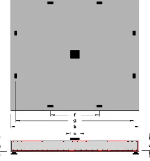
2.2.4 Tests on progressive collapse response of flat slab systems Yi et al. (2014)
Yi et al. (2014) presented half scaled tests of two flat slab systems to assess their static collapse response. Each system comprised of two bays spanning 2.564 m in both orthogonal directions (Figure 2.2). The flat slab specimens were 90 mm thick and supported on 213mm square columns. The first test assessed flat slab system response after the static removal of an internal