LabVIEW
Development Guidelines
Worldwide Technical Support and Product Information ni.com
National Instruments Corporate Headquarters
11500 North Mopac Expressway Austin, Texas 78759-3504 USA Tel: 512 683 0100
Worldwide Offices
Australia 61 2 9672 8846, Austria 43 0 662 45 79 90 0, Belgium 32 0 2 757 00 20, Brazil 55 11 3262 3599, Canada (Calgary) 403 274 9391, Canada (Montreal) 514 288 5722, Canada (Ottawa) 613 233 5949, Canada (Québec) 514 694 8521, Canada (Toronto) 905 785 0085, Canada (Vancouver) 514 685 7530, China 86 21 6555 7838, Czech Republic 42 02 2423 5774, Denmark 45 45 76 26 00,
Finland 385 0 9 725 725 11, France 33 0 1 48 14 24 24, Germany 49 0 89 741 31 30, Greece 30 2 10 42 96 427, Hong Kong 2645 3186, India 91 80 4190000, Israel 972 0 3 6393737, Italy 39 02 413091,
Japan 81 3 5472 2970, Korea 82 02 3451 3400, Malaysia 603 9059 6711, Mexico 001 800 010 0793, Netherlands 31 0 348 433 466, New Zealand 64 09 914 0488, Norway 47 0 32 27 73 00,
Poland 48 0 22 3390 150, Portugal 351 210 311 210, Russia 7 095 238 7139, Singapore 65 6 226 5886, Slovenia 386 3 425 4200, South Africa 27 0 11 805 8197, Spain 34 91 640 0085, Sweden 46 0 8 587 895 00, Switzerland 41 56 200 51 51, Taiwan 886 2 2528 7227, United Kingdom 44 0 1635 523545
For further support information, refer to theTechnical Support and Professional Servicesappendix. To comment on the documentation, send email [email protected].
Important Information
Warranty
The media on which you receive National Instruments software are warranted not to fail to execute programming instructions, due to defects in materials and workmanship, for a period of 90 days from date of shipment, as evidenced by receipts or other documentation. National Instruments will, at its option, repair or replace software media that do not execute programming instructions if National Instruments receives notice of such defects during the warranty period. National Instruments does not warrant that the operation of the software shall be uninterrupted or error free.
A Return Material Authorization (RMA) number must be obtained from the factory and clearly marked on the outside of the package before any equipment will be accepted for warranty work. National Instruments will pay the shipping costs of returning to the owner parts which are covered by warranty.
National Instruments believes that the information in this document is accurate. The document has been carefully reviewed for technical accuracy. In the event that technical or typographical errors exist, National Instruments reserves the right to make changes to subsequent editions of this document without prior notice to holders of this edition. The reader should consult National Instruments if errors are suspected. In no event shall National Instruments be liable for any damages arising out of or related to this document or the information contained in it. EXCEPT AS SPECIFIED HEREIN, NATIONALINSTRUMENTS MAKES NO WARRANTIES,EXPRESS OR IMPLIED,AND SPECIFICALLY DISCLAIMS ANY WARRANTY OF MERCHANTABILITY OR FITNESS FOR A PARTICULAR PURPOSE. CUSTOMER’S RIGHT TO RECOVER DAMAGES CAUSED BY FAULT OR NEGLIGENCE ON THE PART OF NATIONALINSTRUMENTS SHALL BE LIMITED TO THE AMOUNT THERETOFORE PAID BY THE CUSTOMER. NATIONALINSTRUMENTS WILL NOT BE LIABLE FOR DAMAGES RESULTING FROM LOSS OF DATA,PROFITS,USE OF PRODUCTS,OR INCIDENTAL OR CONSEQUENTIAL DAMAGES,EVEN IF ADVISED OF THE POSSIBILITY THEREOF. This limitation of the liability of National Instruments will apply regardless of the form of action, whether in contract or tort, including negligence. Any action against National Instruments must be brought within one year after the cause of action accrues. National Instruments shall not be liable for any delay in performance due to causes beyond its reasonable control. The warranty provided herein does not cover damages, defects, malfunctions, or service failures caused by owner’s failure to follow the National Instruments installation, operation, or maintenance instructions; owner’s modification of the product; owner’s abuse, misuse, or negligent acts; and power failure or surges, fire, flood, accident, actions of third parties, or other events outside reasonable control.
Copyright
Under the copyright laws, this publication may not be reproduced or transmitted in any form, electronic or mechanical, including photocopying, recording, storing in an information retrieval system, or translating, in whole or in part, without the prior written consent of National Instruments Corporation.
Trademarks
LabVIEW™, National Instruments™, NI™, and ni.com™are trademarks of National Instruments Corporation.
Tektronix®and Tek are registered trademarks of Tektronix, Inc. Other product and company names mentioned herein are trademarks or trade names of their respective companies.
Patents
For patents covering National Instruments products, refer to the appropriate location:Help»Patentsin your software, thepatents.txtfile on your CD, orni.com/patents.
WARNING REGARDING USE OF NATIONAL INSTRUMENTS PRODUCTS
(1) NATIONAL INSTRUMENTS PRODUCTS ARE NOT DESIGNED WITH COMPONENTS AND TESTING FOR A LEVEL OF RELIABILITY SUITABLE FOR USE IN OR IN CONNECTION WITH SURGICAL IMPLANTS OR AS CRITICAL COMPONENTS IN ANY LIFE SUPPORT SYSTEMS WHOSE FAILURE TO PERFORM CAN REASONABLY BE EXPECTED TO CAUSE SIGNIFICANT INJURY TO A HUMAN.
(2) IN ANY APPLICATION, INCLUDING THE ABOVE, RELIABILITY OF OPERATION OF THE SOFTWARE PRODUCTS CAN BE IMPAIRED BY ADVERSE FACTORS, INCLUDING BUT NOT LIMITED TO FLUCTUATIONS IN ELECTRICAL POWER SUPPLY, COMPUTER HARDWARE MALFUNCTIONS, COMPUTER OPERATING SYSTEM SOFTWARE FITNESS, FITNESS OF COMPILERS AND DEVELOPMENT SOFTWARE USED TO DEVELOP AN APPLICATION, INSTALLATION ERRORS, SOFTWARE AND HARDWARE COMPATIBILITY PROBLEMS, MALFUNCTIONS OR FAILURES OF ELECTRONIC MONITORING OR CONTROL DEVICES, TRANSIENT FAILURES OF ELECTRONIC SYSTEMS (HARDWARE AND/OR SOFTWARE), UNANTICIPATED USES OR MISUSES, OR ERRORS ON THE PART OF THE USER OR APPLICATIONS DESIGNER (ADVERSE FACTORS SUCH AS THESE ARE HEREAFTER COLLECTIVELY TERMED “SYSTEM FAILURES”). ANY APPLICATION WHERE A SYSTEM FAILURE WOULD CREATE A RISK OF HARM TO PROPERTY OR PERSONS (INCLUDING THE RISK OF BODILY INJURY AND DEATH) SHOULD NOT BE RELIANT SOLELY UPON ONE FORM OF ELECTRONIC SYSTEM DUE TO THE RISK OF SYSTEM FAILURE. TO AVOID DAMAGE, INJURY, OR DEATH, THE USER OR APPLICATION DESIGNER MUST TAKE REASONABLY PRUDENT STEPS TO PROTECT AGAINST SYSTEM FAILURES, INCLUDING BUT NOT LIMITED TO BACK-UP OR SHUT DOWN MECHANISMS. BECAUSE EACH END-USER SYSTEM IS CUSTOMIZED AND DIFFERS FROM NATIONAL INSTRUMENTS' TESTING PLATFORMS AND BECAUSE A USER OR APPLICATION DESIGNER MAY USE NATIONAL INSTRUMENTS PRODUCTS IN COMBINATION WITH OTHER PRODUCTS IN A MANNER NOT EVALUATED OR CONTEMPLATED BY NATIONAL
INSTRUMENTS, THE USER OR APPLICATION DESIGNER IS ULTIMATELY RESPONSIBLE FOR VERIFYING AND VALIDATING THE SUITABILITY OF NATIONAL INSTRUMENTS PRODUCTS WHENEVER NATIONAL INSTRUMENTS PRODUCTS ARE INCORPORATED IN A SYSTEM OR APPLICATION, INCLUDING, WITHOUT LIMITATION, THE APPROPRIATE DESIGN, PROCESS AND SAFETY LEVEL OF SUCH SYSTEM OR APPLICATION.
Contents
About This Manual
Conventions ...ix Related Documentation...x
Chapter 1
Development Models
Common Development Pitfalls...1-1 Lifecycle Models ...1-4 Code and Fix Model ...1-4 Waterfall Model...1-5 Modified Waterfall Model...1-7 Prototyping ...1-7 LabVIEW Prototyping Methods ...1-8 Spiral Model ...1-8 Summary ...1-11
Chapter 2
Incorporating Quality into the Development Process
Quality Requirements ...2-1 Configuration Management ...2-2 Source Code Control ...2-2 Managing Project-Related Files ...2-3 Retrieving Old Versions of Files...2-3 Tracking Changes...2-4 Change Control...2-4 Testing Guidelines ...2-5 Black Box and White Box Testing...2-6 Unit, Integration, and System Testing...2-6 Unit Testing...2-6 Integration Testing ...2-8 System Testing ...2-9 Formal Methods of Verification ...2-9 Style Guidelines ...2-10 Design Reviews ...2-11 Code Reviews ...2-11 Post-Project Analysis ...2-12
Software Quality Standards ... 2-12 International Organization for Standardization ISO 9000 ... 2-13 U.S. Food and Drug Administration Standards ... 2-14 Capability Maturity Model (CMM) ... 2-14 Institute of Electrical and Electronic Engineers (IEEE) Standards... 2-15
Chapter 3
Prototyping and Design Techniques
Defining the Requirements of the Application... 3-1 Top-Down Design ... 3-2 Data Acquisition System Example ... 3-3 Bottom-Up Design... 3-6 Instrument Driver Example... 3-7 Designing for Multiple Developers ... 3-8 Front Panel Prototyping... 3-9 Performance Benchmarking ... 3-10 Identifying Common Operations ... 3-11
Chapter 4
Scheduling and Project Tracking
Estimation... 4-1 Source Lines of Code/Number of Nodes Estimation... 4-2 Problems with Source Lines of Code and Number of Nodes... 4-3 Effort Estimation... 4-4 Wideband Delphi Estimation ... 4-4 Other Estimation Techniques... 4-5 Mapping Estimates to Schedules... 4-6 Tracking Schedules Using Milestones ... 4-7 Responding to Missed Milestones ... 4-7
Chapter 5
Creating Documentation
Designing and Developing Documentation... 5-1 Developing User Documentation ... 5-2 Systematically Organizing Documentation ... 5-2 Documenting a Library of VIs ... 5-3 Documenting an Application ... 5-3 Creating Help Files... 5-4
Describing VIs, Controls, and Indicators...5-4 Creating VI Descriptions ...5-4 Documenting Front Panels ...5-5 Creating Control and Indicator Descriptions...5-5
Chapter 6
LabVIEW Style Guide
Organizing VIs in Directories...6-1 Front Panel Style...6-2 Fonts and Text Characteristics ...6-3 Colors ...6-3 Graphics and Custom Controls...6-4 Layout...6-5 Sizing and Positioning...6-6 Labels ...6-6 Paths versus Strings...6-7 Enumerated Type Controls versus Ring Controls ...6-7 Default Values and Ranges ...6-8 Property Nodes ...6-8 Key Navigation...6-9 Dialog Boxes ...6-9 Block Diagram Style...6-10
Wiring Techniques ...6-10 Memory and Speed Optimization...6-10 Sizing and Positioning...6-13 Left-to-Right Layouts ...6-13 Block Diagram Comments ...6-13 Call Library Function Nodes and Code Interface Nodes ...6-14 Type Definitions...6-14 Sequence Structures...6-14 Icon and Connector Pane Style ...6-15 Icons ...6-15 Example of Intuitive Icons ...6-16 Connector Panes ...6-17 Style Checklist ...6-18 VI Checklist...6-18 Front Panel Checklist ...6-19 Block Diagram Checklist ...6-21
Appendix A
References
Appendix B
Technical Support and Professional Services
Glossary
Index
Figures
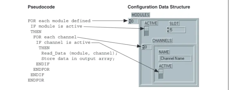
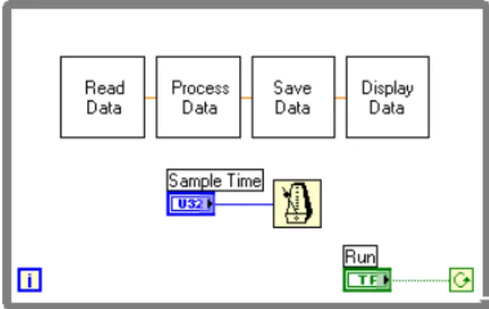
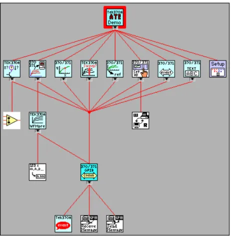
Figure 1-1. Waterfall Lifecycle Model ... 1-5 Figure 1-2. Spiral Lifecycle Model ... 1-9 Figure 2-1. Capability Maturity Model ... 2-15 Figure 3-1. Flowchart of a Data Acquisition System ... 3-4 Figure 3-2. Mapping Pseudocode into a LabVIEW Data Structure ... 3-5 Figure 3-3. Mapping Pseudocode into Actual LabVIEW Code ... 3-5 Figure 3-4. Data Flow for a Generic Data Acquisition Program... 3-6 Figure 3-5. VI Hierarchy for the Tektronix 370A ... 3-8 Figure 3-6. Operations Run Independently ... 3-11 Figure 3-7. Loop Performs Operation Three Times ... 3-11 Figure 6-1. Directory Hierarchy ... 6-2 Figure 6-2. Example of Imported Graphics Used in a Pict Ring... 6-4 Figure 6-3. Using Decorations to Visually Group Objects Together ... 6-5 Figure 6-4. Free Labels on a Boolean Control ... 6-7 Figure 6-5. While Loop with 50 Millisecond Delay... 6-11 Figure 6-6. Report Generation VIs ... 6-16
Table
About This Manual
The LabVIEW Development Guidelines describe many of the issues that arise when developing large applications. The guidelines are based on the advice of LabVIEW developers and provide a basic survey of software engineering techniques you might find useful when developing your own projects.
This manual also includes a discussion of style for creating VIs. Developers who have used LabVIEW and are comfortable in the LabVIEW
environment can use the LabVIEW Development Guidelines to maintain a consistent style in their projects.
Conventions
The following conventions appear in this manual:
» The»symbol leads you through nested menu items and dialog box options to a final action. The sequenceFile»Page Setup»Optionsdirects you to pull down theFilemenu, select thePage Setupitem, and selectOptions
from the last dialog box.
This icon denotes a tip, which alerts you to advisory information.
bold Bold text denotes items that you must select or click in the software, such as menu items and dialog box options. Bold text also denotes parameter names.
italic Italic text denotes variables, emphasis, a cross reference, or an introduction to a key concept. This font also denotes text that is a placeholder for a word or value that you must supply.
monospace Text in this font denotes text or characters that you should enter from the keyboard, sections of code, programming examples, and syntax examples. This font is also used for the proper names of disk drives, paths, directories, programs, subprograms, subroutines, device names, functions, operations, variables, filenames and extensions, and code excerpts.
Related Documentation
The following documents contain information that you might find helpful as you read this manual:
• LabVIEW Help, available by selectingHelp»VI, Function, & How-To Help
• LabVIEW User Manual
• LabVIEW Custom Controls, Indicators, and Type Definitions
Application Note
• LabVIEW Performance and Memory Management Application Note • LabVIEW Unit Validation Test Procedure Application Note • Porting and Localizing LabVIEW VIs Application Note • Using LabVIEW to Create Multithreaded VIs for Maximum
1
Development Models
This chapter provides examples of common development problems and describes different software engineering lifecycle models.
LabVIEW makes it easy to assemble components of data acquisition, test, and control systems. Because creating applications in LabVIEW is so easy, many people begin to develop VIs immediately with relatively little planning. For simple applications, such as quick lab tests or monitoring applications, this approach can be appropriate. However, for larger development projects, good project planning is vital.
Common Development Pitfalls
If you have developed large applications before, some of the following statements probably sound familiar. Most of these approaches start out with good intentions and are quite reasonable. However, these approaches are often unrealistic and can lead to delays, quality problems, and poor morale among team members.
• “I have not really thought it through, but I think that we can complete the project in….”
• Estimates made without planning rarely are accurate because they usually are based on an incomplete understanding of the problem. When developing for someone else, often you each have different ideas about the project requirements. To make accurate estimates, you both must understand the requirements and work through a preliminary high-level design to understand the components you need to develop. • “I think I understand the problem the customer wants to solve, so I can
begin development immediately.”
There are two problems with this statement. The first problem is that a lack of consensus on project goals results in schedule delays. Your idea of what a customer wants might be based on inadequate
communication. Refer to theLifecycle Modelssection of this chapter for more information about developing a list of requirements and prototyping a system. Requirement lists and prototypes are two useful tools for clarifying project goals.
A second problem with this statement is that immediately beginning development frequently means writing code without a detailed design. Just as builders do not construct a building without architectural plans, developers do not begin building an application without a detailed design. Refer to theCode and Fix Modelsection of this chapter for more information about different development models you can follow. • “We do not have time to write detailed plans. We have a strict schedule,
so we need to begin developing immediately.”
This situation is similar to the previous example but is such a common mistake that it is worth emphasizing. Software developers frequently skip important planning steps because planning does not seem as productive as developing code. As a result, developers create VIs without a clear idea of how the VIs all work together. Consequently, you have to rework code as you discover mistakes. Taking the time to develop a plan can prevent costly rework at the development stage. Refer to theLifecycle Modelssection of this chapter and Chapter 3,
Prototyping and Design Techniques, for more information about better approaches to developing software.
• “We can incorporate all the features in the first release. If the application does not include every feature, it is useless.” In some cases, this statement is correct. However, for most applications, developing in stages is a better approach. When you analyze the requirements for a project, prioritize the features. You can develop an initial VI that provides useful functionality in a shorter time at a lower cost. Then you can add features incrementally. The more you try to accomplish in a single stage, the greater the risk of falling behind schedule. Releasing software incrementally reduces schedule pressures and ensures a timely software release. Refer to theLifecycle Modelssection of this chapter for more information about using development models.
• “If I can just get all the features in within the next month, I can fix any problems before the software releases.”
To release high-quality products on time, you must maintain quality standards throughout development. Do not build new features on an unstable foundation and rely on correcting problems later. This development technique exacerbates problems and increases cost. Even if you complete all the features on time, the time required to correct the problems in the existing code and the new code can delay the release of the product. Prioritize features and implement the most important ones first. Once the most important features are tested thoroughly, you can choose to work on lower priority features or defer them to a future release. Refer to Chapter 2,Incorporating Quality into the
Development Process, for more information about techniques for producing high-quality software.
• “We are behind in the project schedule. We need to increase the number of developers working on the project.”
In many cases, increasing the number of developers actually delays the project. Adding developers to a project requires time for training, which takes away time originally scheduled for development. Add resources earlier in the project rather than later. There also is a limit to the number of people who can work on a project effectively. With fewer people, there is less overlap. You can partition the project so each person works on a particular section. The more developers you add, the more difficult it becomes to avoid overlap. Refer to Chapter 2,
Incorporating Quality into the Development Process, for more information about configuration management techniques that can help minimize overlap. Refer to Chapter 3,Prototyping and Design Techniques, for more information about methods for partitioning software for multiple developers.
• “We are behind in the project, but we still think we can get all the features in by the specified date.”
When you are behind in a project, it is important to recognize that fact and adjust your schedule. Assuming you can make up lost time can postpone choices until it becomes too costly to deal with them. For example, if you realize in the first month of a six-month project that you are behind, you can sacrifice a planned feature or add time to the overall schedule. If you do not realize you are behind schedule until the fifth month, you can affect decisions that other developers on your team made. Changing these decisions can be costly.
When you realize you are behind, adjust the schedule or consider features you can drop or postpone to subsequent releases. Do not ignore the delay or sacrifice testing scheduled for later in the process. Numerous other problems can arise when developing software. The following list includes some of the fundamental elements of developing quality software on time.
• Spend sufficient time planning.
• Make sure the whole team thoroughly understands the problems that they must solve.
• Have a flexible development strategy that minimizes risk and accommodates change.
Lifecycle Models
Software development projects are complex. To deal with these complexities, many developers adhere to a core set of development principles. These principles define the field of software engineering. A major component of this field is the lifecycle model. The lifecycle model describes steps to follow when developing software—from the initial concept stage to the release, maintenance, and subsequent upgrading of the software.
Many different lifecycle models currently exist. Each has advantages and disadvantages in terms of time-to-release, quality, and risk management. This section describes some of the most common models used in software engineering. Many hybrids of these models exist, so you can customize these models to fit the requirements of a project.
Although this section is theoretical in its discussion, in practice consider all the steps these models encompass. Consider how you decide what requirements and specifications the project must meet and how you deal with changes to them. Also consider when you need to meet these requirements and what happens if you do not meet a deadline.
The lifecycle model is a foundation for the entire development process. Good decisions can improve the quality of the software you develop and decrease the time it takes to develop it.
Code and Fix Model
The code and fix model probably is the most frequently used development methodology in software engineering. It starts with little or no initial planning. You immediately start developing, fixing problems as they occur, until the project is complete.
Code and fix is a tempting choice when you are faced with a tight development schedule because you begin developing code right away and see immediate results.
Unfortunately, if you find major architectural problems late in the process, you usually have to rewrite large parts of the application. Alternative development models can help you catch these problems in the early concept stages, when making changes is easier and less expensive.
The code and fix model is appropriate only for small projects that are not intended to serve as the basis for future development.
Waterfall Model
The waterfall model is the classic model of software engineering. This model is one of the oldest models and is widely used in government projects and in many major companies. Because the model emphasizes planning in the early stages, it catches design flaws before they develop. Also, because the model is document and planning intensive, it works well for projects in which quality control is a major concern.
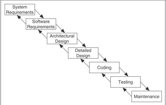
The pure waterfall lifecycle consists of several non-overlapping stages, as shown in Figure 1-1. The model begins with establishing system requirements and software requirements and continues with architectural design, detailed design, coding, testing, and maintenance. The waterfall model serves as a baseline for many other lifecycle models.
Figure 1-1. Waterfall Lifecycle Model
• System requirements—Establishes the components for building the system, including the hardware requirements, software tools, and other necessary components. Examples include decisions on hardware, such as plug-in boards (number of channels, acquisition speed, and so on), and decisions on external pieces of software, such as databases or libraries.
• Software requirements—Establishes the expectations for software functionality and identifies which system requirements the software affects. Requirements analysis includes determining interaction needed with other applications and databases, performance requirements, user interface requirements, and so on.
System Requirements Software Requirements Architectural Design Detailed Design Coding Testing Maintenance
• Architectural design—Determines the software framework of a system to meet the specified requirements. The design defines the major components and the interaction of those components, but the design does not define the structure of each component. You also determine the external interfaces and tools to use in the project.
• Detailed design—Examines the software components defined in the architectural design stage. Produces a specification for how each component is implemented.
• Coding—Implements the detailed design specification. • Testing—Determines whether the software meets the specified
requirements and finds any errors present in the code.
• Maintenance—Addresses problems and enhancement requests after the software releases.
In some organizations, a change control board maintains the quality of the product by reviewing each change made in the maintenance stage. Consider applying the full waterfall development cycle model when correcting problems or implementing these enhancement requests. In each stage, you create documents that explain the objectives and describe the requirements for that phase. At the end of each stage, you hold a review to determine whether the project can proceed to the next stage. You also can incorporate prototyping into any stage from the architectural design and after. Refer to thePrototypingsection of this chapter for more information about using prototyping in projects.
Many people believe you cannot apply this model to all situations. For example, with the pure waterfall model, you must state the requirements before you begin the design, and you must state the complete design before you begin coding. There is no overlap between stages. In real-world development, however, you can discover issues during the design or coding stages that point out errors or gaps in the requirements.
The waterfall method does not prohibit returning to an earlier phase, for example, from the design phase to the requirements phase. However, this involves costly rework. Each completed phase requires formal review and extensive documentation development. Thus, oversights made in the requirements phase are expensive to correct later.
Because the actual development comes late in the process, you do not see results for a long time. This delay can be disconcerting to management and to customers. Many people also think the amount of documentation is excessive and inflexible.
Although the waterfall model has its weaknesses, it is instructive because it emphasizes important stages of project development. Even if you do not apply this model, consider each of these stages and its relationship to your own project.
Modified Waterfall Model
Many engineers recommend modified versions of the waterfall lifecycle. These modifications tend to focus on allowing some of the stages to overlap, thus reducing the documentation requirements and the cost of returning to earlier stages to revise them. Another common modification is to incorporate prototyping into the requirements phases. Refer to the
Prototyping section of this chapter for more information about prototyping. Overlapping stages, such as the requirements stage and the design stage, make it possible to integrate feedback from the design phase into the requirements. However, overlapping stages can make it difficult to know when you are finished with a given stage. Consequently, progress is more difficult to track. Without distinct stages, problems can cause you to defer important decisions until later in the process when they are more expensive to correct.
Prototyping
One of the main problems with the waterfall model is that the requirements often are not completely understood in the early development stages. When you reach the design or coding stages, you begin to see how everything works together, and you can discover that you need to adjust the requirements.
Prototyping is an effective tool for demonstrating how a design meets a set of requirements. You can build a prototype, adjust the requirements, and revise the prototype several times until you have a clear picture of the overall objectives. In addition to clarifying the requirements, a prototype also defines many areas of the design simultaneously.
The pure waterfall model allows for prototyping in the later architectural design stage and subsequent stages but not in the early requirements stages. However, prototyping has its drawbacks. Because it appears that you have a working system, customers may expect a complete system sooner than is possible. In most cases, prototypes are built on compromises that allow it to come together quickly but prevent the prototype from being an effective basis for future development. You need to decide early if you want to use
the prototype as a basis for future development. All parties need to agree with this decision before development begins.
Be careful that prototyping does not become a disguise for a code and fix development cycle. Before you begin prototyping, gather clear
requirements and create a design plan. Limit the amount of time you spend prototyping before you begin. Time limits help to avoid overdoing the prototyping phase. As you incorporate changes, update the requirements and the current design. After you finish prototyping, consider returning to one of the other development models. For example, consider prototyping as part of the requirements or design phases of the waterfall model.
LabVIEW Prototyping Methods
There are a number of ways to prototype a system in LabVIEW. In systems with I/O requirements that are difficult to satisfy, you can develop a prototype to test the control and acquisition loops and rates. In I/O prototypes, random data can simulate data acquired in the real system. Systems with many user interface requirements are perfect for prototyping. Determining the method you use to display data or prompt the user for settings is difficult on paper. Instead, consider designing VI front panels with the controls and indicators you need. Leave the block diagram empty and figure out how the controls work and how various actions require other front panels. For more extensive prototypes, tie the front panels together. However, do not get carried away with this process.
If you are bidding on a project for a client, using front panel prototypes is an extremely effective way to discuss with the client how you can satisfy his or her requirements. Because you can add and remove controls quickly, especially if the block diagrams are empty, you help customers clarify requirements.
Spiral Model
The spiral model is a popular alternative to the waterfall model. It emphasizes risk management so you find major problems earlier in the development cycle. In the waterfall model, you have to complete the design before you begin coding. With the spiral model, you break up the project into a set of risks that need to be dealt with. You then begin a series of iterations in which you analyze the most important risk, evaluate options for resolving the risk, deal with the risk, assess the results, and plan for the next iteration. Figure 1-2 illustrates the spiral lifecycle model.
Figure 1-2. Spiral Lifecycle Model
Risks are any issues that are not clearly defined or have the potential to affect the project adversely. For each risk, consider the following two things:
• The likelihood of the risk occurring (probability) • The severity of the effect of the risk on the project (loss)
You can use a scale of 1 to 10 for each of these items, with 1 representing the lowest probability or loss and 10 representing the highest. Risk exposure is the product of these two rankings.
Cumulative Cost Evaluate Alternatives and Risks Determine Objectives,
Alternatives, and Constraints
Develop and Test Prototype
Plan Next Phase Commit to Next Cycle
Risk Analysis
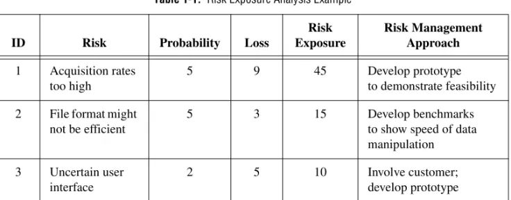
Use a table such as the one in Table 1-1 to keep track of the top risk items of the project.
In general, deal with the risks with the highest risk exposure first. In this example, the first spiral deals with the potential of the data acquisition rates being too high. If after the first spiral, you demonstrate that the rates are high, you can change to a different hardware configuration to meet the acquisition requirements. Each iteration can identify new risks. In this example, using more powerful hardware can introduce higher costs as a new risk.
For example, assume you are designing a data acquisition system with a plug-in data acquisition card. In this case, the risk is whether the system can acquire, analyze, and display data quickly enough. Some of the constraints in this case are system cost and requirements for a specific sampling rate and precision.
After determining the options and constraints, you evaluate the risks. In this example, create a prototype or benchmark to test acquisition rates. After you see the results, you can evaluate whether to continue with the approach or choose a different option. You do this by reassessing the risks based on the new knowledge you gained from building the prototype.
In the final phase, you evaluate the results with the customer. Based on customer input, you can reassess the situation, decide on the next highest risk, and start the cycle over. This process continues until the software is finished or you decide the risks are too great and terminate development. It is possible that none of the options are viable because the options are too expensive, time-consuming, or do not meet the requirements.
Table 1-1. Risk Exposure Analysis Example
ID Risk Probability Loss
Risk Exposure Risk Management Approach 1 Acquisition rates too high 5 9 45 Develop prototype to demonstrate feasibility 2 File format might
not be efficient
5 3 15 Develop benchmarks
to show speed of data manipulation 3 Uncertain user
interface
2 5 10 Involve customer;
The advantage of the spiral model over the waterfall model is that you can evaluate which risks to handle with each cycle. Because you can evaluate risks with prototypes much earlier than in the waterfall process, you can deal with major obstacles and select alternatives in the earlier stages, which is less expensive. With a standard waterfall model, assumptions about the risky components can spread throughout the design, and when you discover the problems, the rework involved can be very expensive.
Summary
Lifecycle models are described as distinct choices from which you must select. In practice, however, you can apply more than one model to a single project. You can start a project with a spiral model to help refine the requirements and specifications over several iterations using prototyping. Once you have reduced the risk of a poorly stated set of requirements, you can apply a waterfall lifecycle model to the design, coding, testing, and maintenance stages.
Other lifecycle models exist. Refer to Appendix A,References, for a list of resources that contain information about other development
2
Incorporating Quality into the
Development Process
This chapter describes strategies for producing quality software.
Many developers who follow the code and fix programming style described in Chapter 1,Development Models, mistakenly believe quality is not an issue until the testing phase. Developers must design quality into a product from the start. Developing quality software begins by selecting a
development model that helps you avoid problems from the beginning. Consider quality during all stages of development—requirements and specifications, design, coding, testing, release, and maintenance. Do not regard quality controls as tedious requirements that impede development. Most quality controls streamline development so you discover the problems before they are in the software, when it is inexpensive to fix them.
Quality Requirements
Set the quality standards for a product during the requirements stage. Treat the desired quality level as a requirement. Weigh the merits and costs of various options you have for applying quality measures to the project. Some of the trade-offs to consider include ease of use versus power and complexity, and speed versus robustness.
For short projects, used only in-house as tools or quick prototypes, you do not need to emphasize robustness. For example, if you decide to develop a VI to benchmark I/O and graphing speeds, error checking is not as crucial. However, with more complicated projects that must be reliable, such as applications for monitoring and controlling a factory process, the software must be capable of handling invalid inputs. For example, if an operator mistakenly selects invalid voltage or current settings, the application must handle them appropriately. Institute as many safeguards as possible to prevent problems. Select a lifecycle development model that helps you find
problems as early as possible and allows time for formal reviews and thorough testing.
Configuration Management
Configuration management is the process of controlling changes and ensuring they are reviewed before they are made. Chapter 1,Development Models, outlines development models, such as the waterfall model. A central focus of these models is to convert software development from a chaotic, unplanned activity to a controlled process. These models improve software development by establishing specific, measurable goals at each stage of development.
Regardless of how well development proceeds, changes that occur later in the process need to be implemented. For example, customers often introduce new requirements in the design stage, or performance problems discovered during development prompt a reevaluation of the design. You also may need to rewrite a section of code to correct a problem found in testing. Changes can affect any component of the project from the requirements and specification to the design, code, and tests. If these changes are not made carefully, you can introduce new problems that can delay development or degrade quality.
Source Code Control
After setting the project quality requirements, develop a process to deal with changes. This process is important for projects with multiple developers. As the developers work on VIs, they need a method for collecting and sharing work. A simple method to deal with this is to establish a central source repository. If all the computers of developers are on the network, you can create a shared location that serves as a central source for development. When developers need to modify files, they can retrieve them from this location. When they are finished with the changes and the system is working, they can return the files to this location. Common files and areas of overlap introduce the potential for accidental loss of work. If two developers decide to work on the same VI at the same time, only one developer can easily merge changes into the project. The other developer must use the Compare VIs tool, available in the LabVIEW Professional Development System, to determine the differences and merge the changes into a new version. Avoid this situation by ensuring good communication among the developers. If each developer notifies the others when he needs to work on a specific VI, the others know not to work
on that VI. However, remain flexible because inevitably, mistakes occur and work is lost.
Source code control tools are a solution to the problem of sharing VIs and controlling access to avoid accidental loss of data. Source code control tools make it easy to set up shared projects and to retrieve the latest files from the server. Once you create a project, you can check out a file for development. Checking out a file marks it with your name so no other developer can modify the file. However, other developers can retrieve the current version of the file from the server. To modify a file, check out the file, make changes, test the changes, and check the file back into the source code control system. After checking in the file, the latest version of the file is available to the whole development team again. Another developer can then check out the file to make further modifications.
Managing Project-Related Files
Source code control tools can manage more than just VIs. Use these tools to manage all aspects of a project—requirements, specifications,
illustrations, reviews, and other documents related to the project. This method ensures that you control access to these documents and share them as needed. Also use these tools to track changes to files and access older versions of files.
Chapter 3,Prototyping and Design Techniques, describes how source management of all project-related files is extremely important for developing quality software. Source management is a requirement for certification under existing quality standards, such as ISO 9000.
Retrieving Old Versions of Files
There are times when you need to retrieve an old version of a file or project. For example, you might change a file, check it in, and then you realize you made a mistake. Another reason for retrieving an old version of a file or project is to send a beta version of the software to a customer and continue development. If the customer reports a problem, you can access a copy of the beta version of the software.
One way to access an old version of a file or project is to back up files periodically. However, unless you back up the VI after every change, you do not have access to every version.
Source code control tools provide a way to check in new versions of a file and make a backup copy of the old version. Depending on how you
configure the system, the tools can maintain multiple backup copies of a file.
You can use source code control tools to label versions of files with descriptive names likebeta,v1.0. You can label any number of files and later retrieve all versions of a file with a specific label. When you release a version of the software, label the files specifically for that version.
Tracking Changes
If you are managing a software project, it is important to monitor changes and track progress toward specific milestone objectives. You also can use this information to determine problem areas of a project by identifying which components required many changes.
Source code control tools maintain a log of all changes made to files and projects. When checking in a file, the tools prompt the developer to write a summary of the changes made. The tool adds this summary information to the log for that file.
You can view the history information for a file or for the system and generate reports that contain the summary information.
In addition, if you back up the project at specific checkpoints, you can use the Compare VIs tool to compare the latest version of a project with another version to verify the changes in the project.
Change Control
Large projects can require a formal process for evaluation and approval of each change request. A formal evaluation system like this can be too restrictive, so be selective when choosing the control mechanisms you introduce into the system.
Cautiously deal with changes to specific components, such as documents related to user requirements, because they generally are worked out through several iterations with the customer. In this case, the word “customer” is used in a general sense. You can be the customer, other departments in your company can be the customer, or you can develop the software under contract for a third party. When you are the customer, adjusting
requirements as you move through the specification and even the design stage is much easier. If you are developing for someone else, changing requirements is more difficult.
Source code control tools give you a degree of control when making changes. You can track all changes, and you can configure the system to maintain previous versions so you can back out of changes if necessary. Some source code control systems give you more options for controlling software change. For example, with Microsoft Visual SourceSafe, Rational Software ClearCase, or Perforce, you can control access to files so some users have access to specific files but others do not. You also can specify that anyone can retrieve files but only certain users can make modifications. With this kind of access control, consider limiting change privileges for requirement documents to specific team members. You also can control access so a user has privileges to modify a file only with the approval of the change request.
The amount of control you apply varies throughout the development process. In the early stages of the project, before formal evaluation of the requirements, you do not need to strictly restrict change access to files nor do you need to follow formal change request processes. Once the
requirements are approved, however, you can institute stronger controls. Apply the same concept of varying the level of control to specifications, test plans, and code before and after completing a project phase.
Testing Guidelines
Decide up front what level of testing the project requires. Engineers under deadline pressure frequently give less attention to testing, devoting more time to other development. With a certain level of testing, you are guaranteed to save time.
Developers must clearly understand the degree to which you expect testing. Also, testing methodologies must be standardized, and results of tests must be tracked. As you develop the requirements and design specifications, also develop a test plan to help you verify that the system and all its components work. Testing reflects the quality goals you want to achieve. For example, if performance is more critical than robustness, develop more tests for performance and fewer that attempt incorrect input or low-memory situations.
Testing is not an afterthought. Consider testing as part of the initial design phases and test throughout development to find and fix problems as soon as possible.
There are a variety of testing methodologies you can use to help increase the quality of VI projects. The following sections describe some testing methodologies.
Black Box and White Box Testing
The method of black box testing is based on the expected functionality of software, without knowledge of how it works. It is called black box testing because you cannot see the internal workings. You can perform black box testing based largely on knowledge of the requirements and the interface of a module. For a subVI, you can perform black box tests on the interface of a subVI to evaluate results for various input values. If robustness is a quality goal, include erroneous input data to see if the subVI successfully deals with it. For example, for numeric inputs, see how the subVI deals with Infinity,<Not A Number>, and other out-of-range values. Refer to the Unit Testing section of this chapter for more examples.
The method of white box testing is designed with knowledge of the internal workings of the software. Use white box testing to check that all the major paths of execution work. By examining a block diagram and looking at the conditions of Case structures and the values controlling loops, you can design tests that check those paths. White box testing on a large scale is impractical because testing all possible paths is difficult.
Although white box testing is difficult to fully implement for large programs, you can choose to test the most important or complex paths. You can combine white box testing with black box testing for more thorough software testing.
Unit, Integration, and System Testing
Use black box and white box testing to test any component of software, regardless of whether it is an individual VI or the complete application. Unit, integration, and system testing are phases of the project at which you can apply black box and white box tests.
Unit Testing
You can use unit testing to concentrate on testing individual software components. For example, you can test an individual VI to see that it works correctly, deals with out-of-range data, has acceptable performance, and that all major execution paths on the block diagram are executed and performed correctly. Individual developers can perform unit tests as they work on the modules.
Some examples of common problems unit tests might account for include the following:
• Boundary conditions for each input, such as empty arrays and empty strings, or0for a size input. Be sure floating point parameters deal with Infinity and<Not A Number>.
• Invalid values for each input, such as-3for a size input. • Strange combinations of inputs.
• Missing files and bad path names.
• What happens when the user clicks theCancelbutton in a file dialog box?
• What happens if the user aborts the VI?
Define various sets of inputs that thoroughly test the VI, write a test VI that calls the VI with each combination of inputs, and checks the results. Use interactive datalogging to create input sets, or test vectors, and retrieve them interactively to re-test the VI. You also can automatically retrieve data from a test VI that performs datalogging programmatically. Refer to the
LabVIEW Unit Validation Test Procedure Application Note for more information about testing VIs.
To perform unit testing, you may need to create a stub of some components that you have not implemented yet or that you are developing still. For example, if you are developing a VI that communicates with an instrument and writes information to a file, another developer can work on a file I/O driver that writes the information in a specific format. To test the
components early, you can create a stub of the file I/O driver by creating a VI with the same interface. This stub VI can write the data in a format that is easy for you to check. You can test the driver with the real file I/O driver later during the integration phase. Refer to theIntegration Testingsection for more information about testing during the integration phase.
Regardless of how you test VIs, record exactly how, when, and what you tested and keep any test VIs you created. This test documentation is especially important if you create VIs for paying customers and for internal use. When you revise the VIs, run the existing tests to ensure you have not broken anything. Also update the tests for any new functionality you added. Refer to the LabVIEW Unit Validation Test Procedure Application Note for more information about unit testing.
Integration Testing
You perform integration testing on a combination of units. Unit testing usually finds most bugs, but integration testing can reveal unanticipated problems. Modules might not work together as expected. They can interact in unexpected ways because of the way they manipulate shared data. Refer to the LabVIEW Performance and Memory Management Application Note for more information about possible problems that are discovered during testing.
You also can perform integration testing in earlier stages before you put the whole system together. For example, if a developer creates a set of VIs that communicates with an instrument, he can develop unit tests to verify that each subVI correctly sends the appropriate commands. He also can develop integration tests that use several of the subVIs in conjunction with each other to verify that there are no unexpected interactions.
Do not perform integration testing as a comprehensive test in which you combine all the components and try to test the top-level program. This method can be expensive because it is difficult to determine the specific source of problems within a large set of VIs. Instead, consider testing incrementally with a top-down or bottom-up testing approach.
With a top-down approach, you gradually integrate major components, testing the system with the lower level components of the system implemented as stubs, as described in theUnit Testingsection of this chapter. Once you verify that the existing components work together within the existing framework, you can enable additional components.
With a bottom-up approach, you test low-level modules first and gradually work up toward the high-level modules. Begin by testing a small number of components combined into a simple system, such as the driver test described in theUnit Testingsection of this chapter. After you combine a set of modules and verify that they work together, add components and test them with the already-debugged subsystem.
The bottom-up approach consists of tests that gradually increase in scope, while the top-down approach consists of tests that are gradually refined as new components are added.
Regardless of the approach you take, you must perform regression testing at each step to verify that the previously tested features still work. Regression testing consists of repeating some or all previous tests. If you need to perform the same tests numerous times, consider developing representative subsets of tests to use for frequent regression tests. You can
run these subsets of tests at each stage. You can run the more detailed tests to test an individual set of modules if problems arise or as part of a more detailed regression test that periodically occurs during development.
System Testing
System testing happens after integration to determine if the product meets customer expectations and to make sure the software works as expected within the hardware system. You can test the system using a set of black box tests to verify that you have met the requirements. With system testing, you test the software to make sure it fits into the overall system as expected. Most LabVIEW applications perform some kind of I/O and also
communicate with other applications. Make sure you test how the application communicates with other applications.
When testing the system, consider the following questions: • Are performance requirements met?
• If my application communicates with another application, does it deal with an unexpected failure of that application well?
You can complete this testing with alpha and beta testing. Alpha and beta testing serve to catch test cases that developers did not consider or complete. With alpha testing, test a functionally complete product in-house to see if any problems arise. With beta testing, when alpha testing is complete, the customers in the field test the product.
Alpha and beta testing are the only testing mechanisms for some companies. Unfortunately, alpha and beta testing actually can be inexact and are not a substitute for other forms of testing that rigorously test each component to verify that the component meets stated objectives. When this type of testing is done late in the development process, it is difficult and costly to incorporate changes suggested as a result.
Formal Methods of Verification
Some testing methodologies attempt to find problems by exploration. But many software engineers are proponents of formal verification of software. Formal methods of verification attempt to prove the correctness of software mathematically.
The principal idea is to analyze each function of a program to determine if it does what you expect. You mathematically state the list of preconditions before the function and the postconditions that are present as a result of the function. You can perform this process either by starting at the beginning
of the program and adding conditions as you work through each function or by starting at the end and working backward, developing a set of weakest preconditions for each function. Refer to Appendix A,References, for information about documents that include more information about the verification process.
This type of testing becomes more complex as more possible paths of execution are added to a program through the use of loops and conditions. Many people believe that formal testing presents interesting ideas for looking at software that can help in small cases, but that verification testing is impractical for most programs.
Style Guidelines
Inconsistent approaches to development and to user interfaces can be a problem when multiple developers work on a project. Each developer has his own style of development, color preferences, display techniques, documentation practices, and block diagram methodologies. One developer may use global variables and sequence structures extensively, while another may prefer to use data flow.
Inconsistent style techniques create software that looks bad. If VIs have different behaviors for the same button, users can become confused and find the user interface of the VIs difficult to use. For example, if one VI requires a user to click a button when he completes a task and another VI requires the user to use a keyboard function key to signal completion of the task, the user can become confused as to what he needs to do.
Inconsistent style also makes software difficult to maintain. For example, if one developer does not like to use subVIs and decides to develop all features within a single large VI, that VI is difficult to modify.
Establish an initial set of guidelines for your VI development team and add additional rules as the project progresses. You can use these style guidelines in future projects.
Chapter 6,LabVIEW Style Guide, provides some style recommendations and checklists to use when working on LabVIEW projects. Use these recommendations and checklists as a basis for developing your own style guidelines. To create a style guide customized to fit the specifications of your project, add, remove, or modify the guidelines provided.
Creating a single standard for development style in any programming language is very difficult because each developer has his own development
style. Select a set of guidelines that works for you and your development team and make sure everyone follows those guidelines.
Design Reviews
Design reviews are a great way to identify and fix problems during development. When you complete the design of a feature, set up a design review with at least one other developer. Discuss quality goals and consider the following questions:
• Does the design incorporate testing? • Is error handling built-in?
• Are there any assumptions in the system that might be invalid? Also look at the design for features that are essential as opposed to features that are extras. Extra features are okay, but if quality and schedule are important, schedule these extra features for later in the development process. This way you can drop or move the list of extra features to subsequent releases if time becomes a constraining factor. Document the results of the design review and any recommended changes.
Code Reviews
A code review is similar to a design review except that it analyzes the code instead of the design. To perform a code review, give one or more developers printouts of the VIs to review. You also can perform the review online because VIs are easier to read and navigate online. Talk through the design and compare the description to the actual implementation. Consider many of the same issues included in a design review. During a code review, ask and answer some of the following questions:
• What happens if a specific VI or function returns an error? Are errors dealt with and/or reported correctly?
• Are there any race conditions? An example of a race condition is a block diagram that reads from and writes to a global variable. There is the potential that a parallel block diagram simultaneously attempts to manipulate the same global variable, resulting in loss of data. • Is the block diagram implemented well? Are the algorithms efficient in
terms of speed and/or memory usage? Refer to the LabVIEW Performance and Memory Management Application Note for more information about creating effective code.
• Is the block diagram easy to maintain? Does the developer make good use of hierarchy, or is he placing too much functionality in a single VI? Does the developer adhere to established guidelines?
There are a number of other features you can look for in a code review. Take notes on the problems you encounter and add them to a list you can use as a guideline for other walk-throughs.
Focus on technical issues when doing a code review. Remember to review only the code, not the developer who produced it. Do not focus only on the negative; be sure to raise positive points as well.
Refer to Appendix A,References, for a list of resources that contain more information about walk-through techniques.
Post-Project Analysis
At the end of each stage in the development process, consider having a post-project analysis meeting to discuss what went well and what did not. Each developer must evaluate the project honestly and discuss obstacles that reduced the quality level of the project. Consider the following questions during a post-project analysis meeting:
• What are we doing right? What works well? • What are we doing wrong? What can we improve?
• Are there specific areas of the design or code that need work? Is a design review or code review of that section necessary?
• Are the quality systems working? Can we catch more problems if we changed the quality requirements? Are there better ways to get the same results?
Post-project analysis meetings at major milestones can help to correct problems mid-schedule instead of waiting until the end of the release cycle.
Software Quality Standards
As software becomes a more critical component in systems, concerns about software quality are increasing. Consequently, a number of organizations have developed quality standards that are specific to software or that can be applied to software. When developing software for some large
organizations, especially government organizations, consider following one of these standards.
The following sections include a brief overview of the most recognized standards. Refer to Appendix A,References, for a list of resources that contain more information about these standards.
International Organization for Standardization ISO 9000
The International Organization for Standardization (ISO) developed the ISO 9000 family of standards for quality management and assurance. Many countries adopted these standards. In some cases, government agencies require compliance with this ISO standard. A third-party auditor generally certifies compliance. The ISO 9000 family of standards is used widely within Europe and Asia. It has not been widely adopted within the United States, although many companies and some government agencies are beginning to use it.
Each country refers to the ISO 9000 family of standards by slightly different names. For example, the United States adopted the ISO 9000 as the ANSI/American Society for Quality Control (ASQC) Q90 Series. In Europe, the European Committee for Standardization (CEN) and the European Committee for Electrotechnical Standardization (CENELEC) adopted the ISO 9000 as the European Norm (EN) 29000 Series. In Canada, the Canadian Standards Association (CSA) adopted the ISO 9000 as the Q 9000 series. However, it is most commonly referred to as ISO 9000 in all countries.
ISO 9000 is an introduction to the ISO family of standards. ISO 9001 is a model for quality assurance in design, development, production, installation, and servicing. Its focus on design and development makes it the most appropriate standard for software products.
Because the ISO 9000 family is designed to apply to any industry, it is somewhat difficult to apply to software development. ISO 9000.3 is a set of guidelines designed to explain how to apply ISO 9001 specifically to software development.
ISO 9001 does not dictate software development procedures. Instead, it requires documentation of development procedures and adherence to the standards you set. Conformance with ISO 9001 does not guarantee quality. Instead, the idea behind ISO 9001 is that companies that emphasize quality and follow documented practices produce higher quality products than companies that do not.
U.S. Food and Drug Administration Standards
The U.S. Food and Drug Administration (FDA) requires all software used in medical applications to meet its Current Good Manufacturing Practices (CGMP). One of the goals of the standard is to make it as consistent as possible with ISO 9001 and a supplement to ISO 9001, ISO/CD 13485. These FDA standards are largely consistent with ISO 9001, but there are some differences. Specifically, the FDA did not think ISO 9001 was specific enough about certain requirements, so the FDA clearly outlined them in its rules.
Refer to the FDA Web site atwww.fda.govfor more information about the CGMP rules and how they compare to ISO 9001.
Capability Maturity Model (CMM)
In 1984, the United States Department of Defense created the Software Engineering Institute (SEI) to establish standards for software quality. The SEI developed a model for software quality called the Capability Maturity Model (CMM). The CMM focuses on improving the maturity of the processes of an organization.
Whereas ISO establishes only two levels of conformance, pass or fail, the CMM ranks an organization into one of five categories.
Level 1. Initial—The organization has few defined processes; quality and schedules are unpredictable.
Level 2. Repeatable—The organization establishes policies based on software engineering techniques and previous projects that were successful. Groups use configuration management tools to manage projects. They also track software costs, features, and schedules. Project standards are defined and followed. Although the groups can deal with similar projects based on this experience, their processes are not usually mature enough to deal with significantly different types of projects.
Level 3. Defined—The organization establishes a baseline set of policies for all projects. Groups are well trained and know how to customize this set of policies for specific projects. Each project has well-defined characteristics that make it possible to accurately measure progress.
Figure 2-1 illustrates the five levels of the CMM and the processes necessary for advancement to the next level.
Figure 2-1. Capability Maturity Model
Most companies are at Level 1 or 2. The U.S. Department of Defense prefers a Level 3 or higher CMM assessment in bids on new government software development. Some commercial companies, mainly in the United States, also use the CMM.
The CMM differs from ISO 9001 in that it is software specific. The ISO specifications are fairly high-level documents, consisting of only a few pages. The CMM is a very detailed document, consisting of more than 500 pages.
Institute of Electrical and Electronic Engineers (IEEE) Standards
IEEE defined a number of standards for software engineering. IEEE Standard 730, first published in 1980, is a standard for software quality assurance plans. This standard serves as a foundation for several Level 4. Managed—The organization sets quality goals for projects and
processes and measures progress toward those goals. Level 5. Optimizing—The organization emphasizes continuous
process improvement across all projects. The organization evaluates the software engineering techniques it uses in different groups and applies them throughout the organization.
Level 5 Optimizing Level 4 Managed Level 3 Defined
Tune Processes Based on Measurements Measure Success of Processes Defined Process for Organization Stable Process for Projects Level 2 Repeatable Level 1 Initial
other IEEE standards and gives a brief description of the minimum requirements for a quality plan in the following areas:
• Purpose
• Reference documents • Management
• Documentation
• Standards, practices, conventions, and metrics • Reviews and audits
• Test
• Problem reporting and corrective action • Tools, techniques, and methodologies • Code control
• Media control • Supplier control
• Records collection, maintenance, and retention • Training
• Risk management
As with the ISO standards, IEEE 730 is fairly short. It does not dictate how to meet the requirements but requires documentation for these practices to a specified minimum level of detail.
In addition to IEEE 730, several other IEEE standards related to software engineering exist, including the following:
• IEEE 610—Defines standard software engineering terminology. • IEEE 829—Establishes standards for software test documentation. • IEEE 830—Explains the content of good software requirements
specifications.
• IEEE 1074—Describes the activities performed as part of a software lifecycle without requiring a specific lifecycle model.
• IEEE 1298—Details the components of a software quality management system; similar to ISO 9001.
Your projects may be required to meet some or all these standards. Even if you are not required to develop to any of these specifications, they can be helpful in developing your own requirements, specifications, and quality plans.
3
Prototyping and Design
Techniques
This chapter provides pointers for project design, including programming approaches, prototyping, and benchmarking.
When you first begin a programming project, deciding how to start can be intimidating. Many LabVIEW developers start immediately with a code and fix development process, building some of the VIs they think are needed. Then they realize they actually need something different from what they have built already. Consequently, people unnecessarily develop, rework, or discard code.
Defining the Requirements of the Application
Before you develop a detailed design of a system, define the goals clearly. Begin by making a list of requirements. Some requirements are specific, such as the types of I/O, sampling rates, or the need for real-time analysis. Do some research at this early stage to be sure you can meet the
specifications. Other requirements depend on user preferences, such as file formats or graph styles.
Try to distinguish between absolute requirements and desires. While you can try to satisfy all requests, it is best to have an idea about which features you can sacrifice if you run out of time.
Be careful that the requirements are not so detailed that they constrain the design. For example, when you design an I/O system, the customer probably has certain sampling rate and precision requirements. However, cost also is a constraint. Include all these issues in the requirements. If you can avoid specifying the hardware, you can adjust the design after you begin prototyping and benchmarking various components. As long as the costs are within the specified budget and the timing and precision issues are met, the customer may not care whether the system uses a particular type of plug-in card or other hardware.