products still remains a challenge. This article focuses on the version models underlying both commercial systems and research prototypes. It provides an overview and classification of different versioning paradigms and defines and relates fundamental concepts such as revisions, variants, configurations, and changes. In particular, we focus on intensional versioning, that is, construction of versions based on configuration rules. Finally, we provide an overview of systems that have had significant impact on the development of the SCM discipline and classify them according to a detailed taxonomy.
Categories and Subject Descriptors: D.2.2 [Software Engineering]: Tools and Techniques—computer-aided software engineering;D.2.6 [Software Engineering]: Programming Environments; D.2.9 [Software Engineering]:
Management—software configuration management;H.2.3 [Database
Management]: Languages—database(persistent) programming languages;H.2.8 [Database Management]: Database Applications; I.2.3 [Artificial Intelligence]: Deduction and Theorem Proving—deduction, logic programming
General Terms: Languages, Management
Additional Key Words and Phrases: Changes, configuration rules, configurations, revisions, variants, versions
1. INTRODUCTION
Software configuration management (SCM) is the discipline of managing the evolution of large and complex software systems [Tichy 1988]. The importance of SCM has been widely recognized, as reflected in particular in the Capability
Maturity Model (CMM) developed by the Software Engineering Institute (SEI) [Humphrey 1989; Paulk et al. 1997]. CMM defines levels of maturity in order to assess software development processes in organizations. Here SCM is seen as one of the key elements for
This work was partially performed during a sabbatical in which the second author spent August through October 1995 in Trondheim. Support from NTNU is gratefully acknowledged.
Authors’ addresses: R. Conradi, Department of Computer and Information Science, Norwegian Univer-sity of Science and Technology (NTNU), N-7034 Trondheim, Norway; B. Westfechtel, Department of Computer Science III, Aachen University of Technology, D-52056 Aachen, Germany.
Permission to make digital / hard copy of part or all of this work for personal or classroom use is granted without fee provided that the copies are not made or distributed for profit or commercial advantage, the copyright notice, the title of the publication, and its date appear, and notice is given that copying is by permission of the ACM, Inc. To copy otherwise, to republish, to post on servers, or to redistribute to lists, requires prior specific permission and / or a fee.
moving from “initial” (undefined pro-cess) to “repeatable” (project manage-ment, SCM, and quality assurance have come into operation). Furthermore, SCM plays an important role in achiev-ing ISO 9000 conformance.
SCM serves different needs [Feiler 1991a].
—As a management support discipline, SCM is concerned with controlling changes to software products. It is this view of SCM that is addressed in the classical textbook by Bersoff et al. [1980] and the IEEE standard [IEEE 1983; IEEE 1988]. According to the latter, SCM covers functionalities such as identification of product com-ponents and their versions, change
control (by establishing strict proce-dures to be followed when performing a change), status accounting (record-ing and report(record-ing the status of compo-nents and change requests), and audit and review (quality assurance func-tions to preserve product consistency). Thus SCM is seen as a support disci-pline for project managers.
—As a development support discipline, SCM provides functions that assist developers in performing coordinated changes to software products. This view of SCM is described, for exam-ple, in the textbook by Babich [1986]. To support developers, SCM is in charge of accurately recording the composition of versioned software products evolving into many revisions and variants, maintaining consis-tency between interdependent compo-nents, reconstructing previously
re-corded software configurations,
building derived objects (compiled code and executables) from their sources (program text), and construct-ing new configurations based on de-scriptions of their properties.
In this article, SCM is primarily con-sidered a development support disci-pline. We provide an overview ofversion modelsimplemented both in commercial systems and research prototypes. A sion model defines the objects to be ver-sioned, version identification and orga-nization, as well as operations for retrieving existing versions and con-structing new versions. Software objects and their relationships constitute the product space, their versions are orga-nized in the version space. A versioned object base combines product and ver-sion space. A specific verver-sion model is characterized by the way the version space is structured, by the decision of which objects are versioned both exter-nally (from the user’s point of view) and internally (within the versioned object base), by the relationships among ver-sion spaces of different objects, and by the way reconstruction of old and con-struction of new versions are supported. CONTENTS
1. INTRODUCTION 2. PRODUCT SPACE
2.1 Software Objects 2.2 Relationships
2.3 Representations of the Product Space 3. VERSION SPACE
3.1 Versions, Versioned Items, and Deltas 3.2 Extensional and Intensional Versioning 3.3 Intents of Evolution: Revisions, Variants, and
Cooperation
3.4 Representations of the Version Space: Version Graphs and Grids
3.5 State-Based and Change-Based Versioning 4. INTERPLAY OF PRODUCT SPACE AND VERSION
SPACE
4.1 AND/OR Graphs 4.2 Granularity of Versioning 4.3 Deltas
4.4 Relations Between Version Model and Data Model
5. INTENSIONAL VERSIONING
5.1 Problem: Combinability Versus Consistency Control and Manageability
5.2 Conceptual Framework for Intensional Version-ing
5.3 Configuration Rules
5.4 Configurators: Tools for Evaluating Configura-tion Rules
5.5 Merge Tools
6. VERSION MODELS IN SCM SYSTEMS 6.1 Overview
6.2 Taxonomy-Based Classification 6.3 Descriptions of SCM Systems 7. RELATED WORK
7.1 Related Work on Version Models 7.2 Related Disciplines
Neighbors 1986], or system modeling languages [Marzullo and Wiebe 1986]. These languages are typically used to represent versions of modules and rela-tionships such as imports, include de-pendencies, and the like. Finally,
sev-eral SCM systems are founded on
databases and manage versions of ob-jects and relationships stored in the da-tabase. Different data models have been used, including EER [Dittrich et al. 1986; Oquendo et al. 1989], object-ori-ented [Estublier and Casallas 1994], and deductive [Zeller and Snelting 1995] ones.
The variety of formalisms makes it difficult to compare the version models of different SCM systems with one an-other. In addition, each system comes with its own terminology. On the other hand, the underlying concepts are often very similar. In order to reveal these concepts, we introduce a unified termi-nology. Furthermore, to describe ver-sion models in a uniform, “canonical”
formalism, we use graphs at many
places in the article. A graph consists of nodes and edges representing entities and (binary) relationships, both of which may be decorated with attributes. Graphs are well suited to represent the organization of a versioned object base, even if the corresponding system is not graph-based. For example, SCCS [Roch-kind 1975] and RCS [Tichy 1985] are both file-based, but the version space of a text file may be represented naturally as a version graph. Other formalisms are used as required, such as textual languages for expressing configuration rules.
The main contribution of this article
only in constructing SCM systems but also in tailoring them more flexibly to the needs of their users. Multiple para-digms could be supported in parallel, allowing users to switch back and forth as required. Furthermore, as noted in Brown et al. [1991], a uniform model would constitute a common foundation for integrating heterogeneous SCM sys-tems in a federated architecture.
In the interest of a thorough discus-sion, we focus on core issues of version-ing, namely, the organization of the ver-sion space, the interrelations of product space and version space, and the con-struction of consistent configurations. Other issues considered essential parts of SCM are only discussed briefly, in particular, management of workspaces, construction of derived objects, coopera-tion, and distribution: all these issues are related to version management, but elaborating on them goes beyond the scope of this article.
The article is structured as follows. Before introducing versions, the product space is described in Section 2. Subse-quently, we discuss the version space without making any assumptions about the product space (Section 3). The inter-play of product and version space is addressed in Section 4. Section 5 is de-voted tointensional versioning(i.e., con-struction of versions based on rules de-scribing consistent combinations). Section 6 provides an overview of sys-tems that have had significant impact on the development of the SCM disci-pline. Related work is discussed in Sec-tion 7, and a short conclusion is given in Section 8.
2. PRODUCT SPACE
The product space describes the struc-ture of a software product without tak-ing versiontak-ing into account (in other words, we assume only one version of a software product). The product space can be represented by a product graph whose nodes and edges correspond to software objects and their relationships, respectively. Different version models vary in their assumptions with respect to the product space. These differences refer to the types of software objects and relationships, to the granularity of object representations, and to the se-mantic levels of modeling.
2.1 Software Objects
A software objectrecords the result of a development or maintenance activity. An SCM system has to manage all kinds of software objects created throughout the software life cycle, including re-quirements specifications, designs, doc-umentations, program code, test plans, test cases, user manuals, project plans, and the like.
Identification is an essential function provided by SCM. Thus, each software object carries an object identifier (OID) that serves to identify it uniquely within a certain context. An external OID is a name assigned by the user, whereas a system-generated, unique OID may be used internally.
Software objects are rather coarse-grained units that are structured inter-nally. For example, a program module is composed of declarations and state-ments, and a documentation consists of sections and paragraphs. Thus a soft-ware object is composed of more fine-grainedunits.
The data model used for representing the product space may or may not dis-tinguish explicitly between coarse-grained and fine-coarse-grained units. For example, file systems make this distinc-tion, whereas many object-oriented data models represent coarse- and fine-grained units in a uniform way. In the
following, we represent the contents of software objects in long attributes at-tached to nodes of the product graph.
Software objects may have different representations, depending on the types of tools operating on them. In toolkit environments, software objects are stored as text files [Rochkind 1975]. In contrast, syntax trees [Habermann and Notkin 1986] or graphs [Nagl 1996] are used in structure-oriented environ-ments. As discussed later, these repre-sentations influence the functionality of an SCM system. For example, a diff command for comparing two versions of a program module returns differing text lines in the case of text files and differ-ing syntactic units in the case of syntax trees, respectively.
Independently of the representation chosen for software objects, we may dis-tinguish between domain-independent and domain-specific models of the prod-uct space. Domain-independent models make no assumptions about the types of software objects to be maintained. All software objects produced throughout the whole software lifecycle project are subject to version control [Tichy 1985]. Domain-specific models are tailored to-wards specific types of software objects (e.g., abstract data types in algebraic specifications) [Ehrig et al. 1989]. 2.2 Relationships
Software objects are connected by vari-ous types of relationships. Composition relationships are used to organize soft-ware objects with respect to their gran-ularity. For example, a software product may be composed of subsystems, which in turn consist of modules. Objects that are decomposed are calledcomposite ob-jects or configurations. Objects residing at the leaves of the composition hierar-chy are denoted atomic objects. Note that an “atomic” software object is still structured internally; that is, it has a fine-grained content. The root of a com-position hierarchy is called the (soft-ware) product.
tion hierarchy (trees, DAGs), and the existence of a component may depend on the existence of its superobject(s). Furthermore, there may be constraints with respect to long attributes (e.g., long attributes may be attached only to leaves of the composition hierarchy). Fi-nally, a composite object may act as a unit with respect to structural opera-tions (e.g., copy or delete), abstraction (encapsulation of components), concur-rency control (locking of a composite object includes locking of its compo-nents), and version control.
Dependency relationships (simply called dependencies in the following) es-tablish directed connections between ob-jects that are orthogonal to composition relationships. They include, for exam-ple, lifecycle dependencies between re-quirements specifications, designs, and module implementations, import or in-clude dependencies between modules, and build dependencies between com-piled code and source code.
The source and the target of a depen-dency correspond to a dependent and a master object, respectively. A depen-dency implies that the contents of the dependent must be kept consistent with the contents of the master. Thus the dependent may have to be changed when the master is modified.
Software objects are further classified intosource objectsandderived objects.A source object is created by a human who is supported by interactive tools, for ex-ample, text editors or graphical editors. A derived object is created automati-cally by a tool, for example, a compiler or linker. Note that the classification of a software object as a source or derived
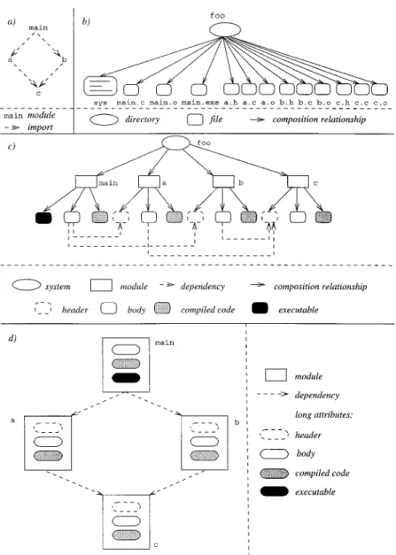
tions to be performed are specified by build rules. The build tool has to ensure that build steps corresponding to these rules are executed in the correct order; that is, build dependencies must be taken into account. In contrast, source dependencies represent relationships between source objects (e.g., lifecycle dependencies as mentioned previously). 2.3 Representations of the Product Space Figure 1 illustrates different represen-tations of a sample software productfoo which is implemented in the program-ming language C. Part (a) shows the modules of foo and their import depen-dencies. The top-level module main im-ports from a and b, which both import fromc. foomay be represented in differ-ent ways. Some examples are given in (b), (c), and (d):
—In (b), foois stored in the file system. Each module is represented by multi-ple files. The suffixes .h, .c, .o, and .exe denote header files, body files, compiled code, and executables, re-spectively. Dependencies and build steps are stored in a text file (the system model sys, e.g., a make file [Feldman 1979]).
—In (c), we assume a data model that supports typed objects and relation-ships (e.g., an EER model as used in PCTE [Oquendo et al. 1989]). As in the file system representation, there is still a composition tree whose leaves correspond to single files. How-ever, dependencies are not repre-sented in a separate text file. Rather, the tree is augmented with
relation-ships reflecting include dependencies. Build dependencies are not given ex-plicitly because they can be computed automatically from source dependen-cies and composition relationships. —In (d), there is no longer a spanning
tree, and all files making up a module are summarized in one object. Fur-thermore, only a single type of rela-tionship is used, which represents source dependencies between
mod-ules.1 This organization, which has been realized, for example, in POEM [Lin and Reiss 1995], corresponds di-rectly to the logical structure dis-played in (a).
1This relationship may be annotated by an at-tribute that distinguishes between include depen-dencies emanating from header and body.
state it represents or in terms of some changes relative to some baseline, it selects a suitable representation for the version set (e.g., version graphs), and it also provides operations for retrieving old versions and constructing new ver-sions.
The characterization of version mod-els given in this section is still incom-plete. Although the previous section
de-scribed the product space without
taking versioning into account, the cur-rent section conversely focuses on the version space, abstracting from the product space. Thus we are not con-cerned with the kinds of items put un-der version control, and we also con-sider versions of a single item only. However, a version model needs to ad-dress the interplay between product space and version space as well (Section 4).
3.1 Versions, Versioned Items, and Deltas A version v represents a state of an evolving item i. v is characterized by a pair v 5 (ps, vs), where ps and vs denote a state in the product space and a point in the version space, respec-tively. The term item covers anything that may be put under version control, including, for example, files and directo-ries in file-based systems, objects stored in object-oriented databases, entities, relationships, and attributes in EER da-tabases, and so on. Versioning can be applied at any level of granularity, ranging from a software product down to text lines.
Aversioned itemis an item that is put
Within a versioned item, each version must be uniquely identifiable through a version identifier (VID). Many SCM sys-tems automatically generate unique version numbers and offer additional symbolic (user-defined) names serving as primary keys. However, a version can also be identified by an expression, which is the identification scheme used by intensional versioning.
All versions of an item share common properties called invariants. These in-variants can be represented, for exam-ple, by unversioned attributes or rela-tionships. Which invariants are shared by versions depends on the specific ver-sion model or the way it is customized to a certain application. At one end of the spectrum, versions virtually share only a common OID. For example, in systems such as SCCS and RCS ver-sions of a text file may differ in arbi-trary ways. At the other end of the spectrum, versions must share semantic properties. For example, version control in algebraic specification [Ehrig et al. 1989] enforces that all versions of a module body realize the shared inter-face.
Versions differ with respect to specific properties (e.g., represented by ver-sioned attributes). The difference be-tween two versions is called a delta. This term suggests that differences should be small compared to invariants. Delta can be defined in two ways (Fig-ure 2):
—a symmetric delta between two ver-sions v1 and v2 consists of properties
v2 \ v1, respectively, where \ denotes
set difference); or
—a directed delta,also called a change, is a sequence of (elementary) change operations op1. . .opm which, when applied to one version v1, yields an-other version v2 (note the
correspon-dence to transaction logs in databases). In practice, deltas are not necessarily small. In the worst case, the common part ofv1andv2 may even be empty. In fact, items may undergo major changes, and the common properties may become smaller and smaller the more versions are created. For example, it is usually unrealistic to assume that all versions of module bodies realize the same inter-face (this assumption is made, e.g., in the algebraic approach already cited [Ehrig et al. 1989] and in the Gandalf system [Kaiser and Habermann 1983]). On the other hand, common properties do have to be asserted because other-wise it does not make sense to group versions at all.
A way out of this dilemma is multi-level versioning; that is, a version may have versions themselves. For example, in Adele [Estublier 1985] a module has multiple versions of interfaces each of which is realized by a set of body ver-sions. DAMOKLES [Dittrich et al. 1986] generalizes this idea and supports re-cursive versioning; that is, any version may be versioned in turn.
3.2 Extensional and Intensional Versioning A versioned item is a container for a set V of versions. The functionality of
ver-sion control is heavily influenced by the wayVis defined.Extensional versioning means thatVis defined by enumerating its members:
V5$v1,. . .,vn%.
Extensional versioning supports re-trieval of previously constructed ver-sions (which is a necessary requirement to any version model). All versions are explicit and have been checked in once before. Each version is typically identi-fied by a unique number. The user in-teracting with the SCM system re-trieves some version vi, performs changes on the retrieved version, and finally submits the changed version as a new version vi11. To ensure safe re-trieval of previously constructed ver-sions, versions can be made immutable. In many systems, all versions are made immutable when they are checked into the object base [Rochkind 1975]; in oth-ers, explicit operations are provided to freeze mutable versions [Westfechtel 1996]. Furthermore, immutability may be enforced selectively (e.g., by distin-guishing between mutable and immuta-ble attributes [Estublier and Casallas 1995]).
Intensional versioning is applied when flexible automatic construction of consistent versions in a large version space needs to be supported. Instead of enumerating its members, the version set is defined by a predicate:
V5$vuc~v!%. Figure 2. Deltas: (a) symmetric; (b) directed.
may be considered the VID of the ver-sion). In this case, a query corresponds to a (partial or total) function q that creates versions in V based on
at-tributes ranging over the domains
A1. . .An:
q: A1 x. . . x An 3 V.
Here the term “attribute” is used in a general way; for example, attributes may identify variants (e.g., an os at-tribute determining the operating sys-tem) or changes (e.g., a Boolean at-tribute Fixto indicate whether a certain bug fix should be included or omitted).
The difference between extensional and intensional versioning may be illus-trated by comparing SCCS [Rochkind 1975] and RCS [Tichy 1985] to condi-tional compilation as, for example, sup-ported with the C programming lan-guage [Kernighan and Ritchie 1978]. SCCS and RCS store and reconstruct versions of text files (extensional ver-sioning). The preprocessor used for con-ditional compilation constructs any source file based on the values of pre-processor variables (intensional version-ing). All fragments of the source file are excluded whose conditions evaluate to false.
From SCCS/RCS and conditional com-pilation, SCM systems have been devel-oped that differ significantly in their versioning capabilities. On the other hand, it must be emphasized that exten-sional and intenexten-sional versioning are by no means mutually exclusive, but can (and should) be combined into a single SCM system.
overwriting, old revisions are preserved to support maintenance of software de-livered to customers, to recover from erroneous updates, and so on.
Versions intended to coexist are called variants. For example, variants of data structures may differ with re-spect to storage consumption, run-time efficiency, and access operations. Fur-thermore, a software product may sup-port multiple operating systems or win-dow systems.
Finally, versions may also be main-tained to support cooperation. In this case, multiple developers work in paral-lel on different versions. Each developer operates in a workspace [Estublier 1996] that contains the versions created and used. Cooperation policies regulate when versions are exported from or im-ported into a workspace. These issues are closely related to software process management and in the following are only discussed in passing (see also Sec-tion 7.2).
3.4 Representations of the Version Space: Version Graphs and Grids
Many SCM systems use version graphs for representing version spaces. A ver-sion graph consists of nodes and edges corresponding to (groups of) versions and their relationships, respectively. Since a version graph assumes an ex-plicitly given set of versions, it is ap-plied in conjunction with extensional versioning. Despite the limitations dis-cussed in the following, they are widely used in practice.
graphs is conceivable, the mainstream of SCM systems is based on a small number of graph types.
In the simplest case (one-level organi-zation), a version graph consists of a set of versions connected by relationships of a single type, called successor relation-ships. A version graph of this type pri-marily represents the evolution history of a versioned item. “v2 is a successor of
v1” means thatv2has been derived from v1, for example, by modifying a copy of
v1.
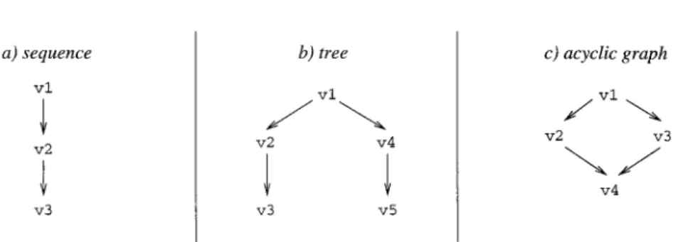
Version graphs may have different shapes (Figure 3). In the most restric-tive case, versions are organized into a sequence of revisions. In a version tree, successors of nonleaf versions may be created, for example, in order to main-tain old versions that have already been delivered to a customer. In an acyclic graph, a version may have multiple pre-decessors, for example, in order to ex-press that a bug fix in an old version is merged with the currently developed version.
Several SCM systems use one of these different kinds of one-level organiza-tion, for example, sequences in NSE [Adams et al. 1989] and acyclic graphs
in PCTE [Oquendo et al. 1989].
DAMOKLES [Dittrich et al. 1986] sup-ports user-defined structural con-straints. The structure of a version graph may be defined in the database schema as a sequence, a tree, or a di-rected acyclic graph.
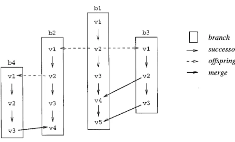
In two-level organization, a version graph is composed of branches, each of which consists of a sequence of
revi-sions. Here at least two relationship types are required, called successor (within a branch) and offspring (be-tween branches) in Figure 4. This orga-nization is applied, for example, in RCS. ClearCase [Leblang 1994] goes beyond
the RCS organization by recording
merges in the version graph. By means of merging, changes performed on one branch can be propagated to another branch. Essentially, this results in a directed acyclic graph. However, the branches are not joined; rather, each of them continues to exist.
Version graphs as presented previ-ously support management of variants only to a limited extent. Variants can be represented by branches as long as their number is small. In the case of multidimensional variation, this ap-proach breaks down because the num-ber of branches explodes combinatori-ally. Let us assume that each dimension is modeled by an attribute with domain Ai. Then the number of branches b is dominated by the product of the domain cardinalities:
b#uA1u. . .uAnu.
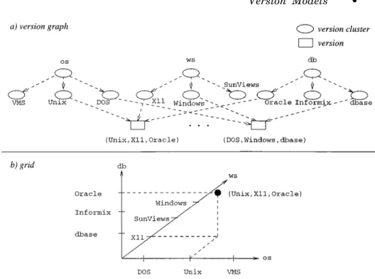
To illustrate this, let us assume that our sample product foo varies with re-spect to the operating system (DOS, Unix, VMS), the database system (Ora-cle, Informix, dbase), and the window system (X11, SunViews, Windows). In this case, up to 27 branches would be required.
This problem can be solved in the following ways.
—Version graphs may be generalized in order to support multidimensional variation. In Figure 5(a), versions are organized into clusters that are used to construct classification hierarchies [Dittrich and Lorie 1988].
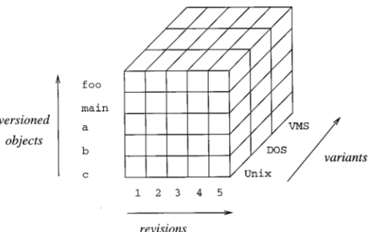
—Alternatively, versions may be ar-ranged in a grid (Figure 5b), that is, ann-dimensional space whose dimen-sions correspond to variant attributes [Sciore 1994].
Figure 5 illustrates only the variant space, assuming that there is no evolu-tion along the time axis. Revisions can be represented in the grid by adding a time dimension (orthogonal version management [Reichenberger 1994]). In the case of the version graph, one level may be added at the bottom and succes-sor relationships may be introduced to represent histories.
3.5 State-Based and Change-Based Versioning
In Section 3.1, a version has been de-fined as a state of an evolving item. Version models that focus on the states of versioned items are called state-based. In state-based versioning, ver-sions are described in terms of reviver-sions and variants.
Changes provide an alternative way of characterizing versions. In
change-based models, a version is described in terms of changes applied to some base-line. To this end, changes are assigned change identifiers (CID) and potentially further attributes to characterize the reasons and the nature of a change. Change-based versioning provides a nice link to change requests: a change request is implemented by a (possibly composite) change. Thus a version may be described in terms of the change requests it implements.
“State- versus change-based” is or-thogonal to “extensional versus inten-sional.” State-based extensional version-ing is provided, for example, by SCCS and RCS and state-based intensional versioning can be realized, for example, by conditional compilation: preprocessor variables can be used to represent vari-ants, and a state may be specified by tuples of values for these variables. However, we emphasize that in general conditional compilation can be used for both state- and change-based versioning (the latter is done, e.g., in the COV system [Gulla et al. 1991]).
Change-based versioning comes in two forms. In the case of change-based extensional versioning,the version set is defined explicitly by enumerating its members and each version is described by the changes relative to some base-line. Thus changes are used only for Figure 4. Version graphs (two-level organization).
documentation. The OVUM report about SCM systems [Rigg et al. 1995] uses the term change packageto denote this form of change-based versioning. Several SCM systems support change packages by annotating versions in ver-sion graphs with change identifiers (e.g., ClearCase and PCMS).
In change-based intensional version-ing,changes are combined freely to con-struct new versions as required. There-fore a change is considered a partial functionc:V3V, whereVdenotes the set of all potential versions of some item. A version v is constructed by ap-plying a sequence of changesc1 . . .cnto a baselineb:
v5c1 o. . . o cn~b!5cn~. . . c1~b!. . .!. The OVUM report (and also the sur-vey by Feiler [1991a]) adopts the termi-nology coined by the Aide-de-Camp
sys-tem [Software Maintenance and
Development Systems 1990] and calls this form of versioning the change set model. Further examples of systems supporting change-based intensional
versioning are the COV system [Gulla et al. 1991], PIE [Goldstein and Bobrow 1980], DaSC [MacKay 1995], and As-gard [Micallef and Clemm 1996].
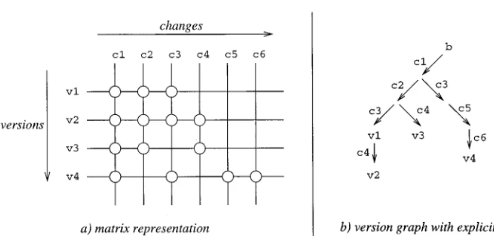
The change space (version space structured in terms of changes) can be represented in different ways. The COV system arranges versions in an n -di-mensional grid called option space. Each change corresponds to a Boolean option that is set to true (false) if the change is applied (omitted). The Aide-de-Camp documentation introduces a matrix representation as shown in Fig-ure 6(a). Lines and columns correspond to versions and changes, respectively. The application of a change is indicated by a circle at an intersection point. For example, v1 is constructed by applying c1, c2, andc3in order.
Figure 6(b) illustrates the relations to the version graphs introduced in Fig-ures 3 and 4, respectively. The versions shown in (a) are arranged in a graph whose nodes and edges correspond to versions and changes, respectively. b denotes the baseline, and intermediate Figure 5. n-dimensional variant space: (a) version graph; (b) grid.
versions are anonymous. For example, the path frombtov1again contains the changes c1, c2, and c3. This version graph explicitly expresses all changes included in a certain version, and there-fore provides more information than the version graphs shown in Figures 3 and 4. In particular, it makes explicit when certain changes were applied to multi-ple versions. For exammulti-ple, c4 was used to construct both v2andv3. In contrast, state-based versioning does not name the changes; that is, the changes are
anonymous. As a consequence, the
changes applied to a version must be deduced from the topology of the version graph. This may become difficult if merging is applied in extensive and complicated ways (or even impossible if merges are not recorded at all).
4. INTERPLAY OF PRODUCT SPACE AND VERSION SPACE
In Section 2, the product space was described under the assumption that only one version of each item is main-tained. In Section 3, basic definitions for versioning were given without con-sidering the product space. The current section combines product space and ver-sion space into aversioned object base.
So far, we have considered versioning of a single item only, and we have made no assumptions concerning the kinds of
items put under version control. As mentioned earlier, a version model needs to address the interplay between product space and version space as well. In the following, we discuss those as-pects of version models that are con-cerned with this interplay. In particu-lar, we investigate which items are put under version control, at what granular-ity versioning is applied both externally and internally, how versions of different items are interrelated, what models are used for representing versioned object bases, and how the version model may be related to the data model.
4.1 AND/OR Graphs
AND/OR graphs [Tichy 1982a] provide a general model for integrating product space and version space. An AND/OR graph contains two types of nodes, namely, AND nodes and OR nodes. Analogously, a distinction is made be-tween AND and OR edges, which ema-nate from AND and OR nodes, respec-tively. An unversioned product graph can be represented by an AND/OR graph consisting exclusively of AND nodes/edges. Versioning of the product graph is modeled by introducing OR nodes. Versioned objects and their ver-sions are represented by OR nodes and AND nodes, respectively.
Note that the version graph illus-Figure 6. Change space: (a) matrix representation; (b) version graph with explicit changes.
trated in Figure 5(a) can be regarded as an AND/OR graph as well: version clus-ters and versions correspond to OR nodes and AND nodes, respectively. However, in the following we are not concerned with the capabilities of AND/OR graphs to model the version space of a single object. Rather, we are interested in the relations between ver-sions of different objects, abstracting for the moment from the ways in which their version spaces are structured. Therefore in the following a versioned object is simply represented by an OR node whose outgoing edges point to its versions.
AND edges are used to represent both composition and dependency relation-ships. A relationship is bound to a spe-cific version if the corresponding AND edge ends at an AND node; otherwise it is called generic.Aconfiguration is rep-resented by a subgraph spanned by all nodes that are transitively reachable from the root node of the configuration. If all AND edges belonging to this sub-graph are bound, the configuration is called bound as well; otherwise it is called generic. Furthermore, we may distinguish between partially and to-tally generic configurations. In the first case, there are both bound and generic AND edges; in the latter case, all AND edges are generic. A bound configura-tion can be constructed from a generic configuration by eliminating the OR nodes, that is, by selecting one succes-sor of each OR node reached during traversal from the root node.
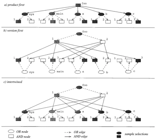
In the following, we return to the examples of product graphs in Figure 1 and compare several approaches to ver-sioning the product graph. Figure 7 shows AND/OR graphs that are all based on Figure 1(b).2 In Figure 7(a) only atomic software objects are ver-sioned.foorepresents a generic configu-ration. In Figure 7(b)foois versioned as
well. Each version of foocorresponds to a bound configuration. In Figure 7(c) references to components are generic, and the versions of foo therefore repre-sent generic configurations.
Using this figure, we may classify ver-sion models according to the selection orderduring the configuration process: —Product first(Figure 7(a)) means that
the product structure is selected first; subsequently, versions of components are selected. This approach is fol-lowed, for example, by SCCS and RCS. It suffers from the restriction that structural versioning cannot be expressed (the product structure is the same for all configurations). —Version first(Figure 7(b)) inverts this
approach: the product version is se-lected first and uniquely determines the component versions. Different product versions may be structured in different ways. For example, a version of component c is contained only in foo.1(version1 of productfoo). PCTE [Oquendo et al. 1989] is an example of an SCM system using this organiza-tion.
—Intertwined (Figure 7(c)) means that AND and OR selections are performed in alternating order. The intertwined organization is used, for example, by ClearCase [Leblang 1994], which ver-sions both files and directories. Again, this selection scheme supports struc-tural versioning.
Thus, “version first” and “inter-twined” both take into account that dif-ferent versions of an object may vary with respect to their relationships to (versions of) other objects. This means that in addition to objects, relationships are versioned as well.
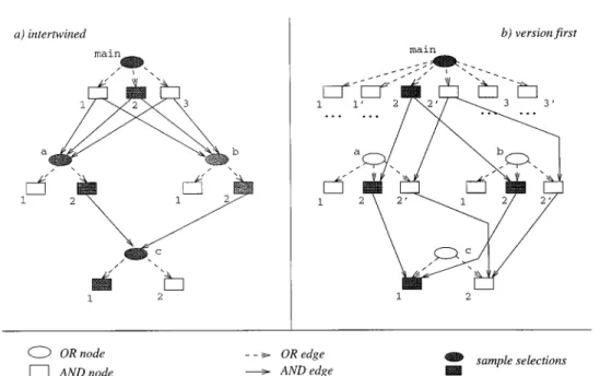
So far, we have applied versioning only to the product graph organization shown in Figure 1(b). In Figure 8, the alternatives “intertwined” and “version first” are illustrated for the product graph of Figure 1(d) (To save space, “product first” has been omitted). In contrast to the previous figure, AND
2Module versions are identified by numbers. For the sake of simplicity, each module version is represented by a single node (e.g., no distinction between header files and bodies).
edges represent dependencies instead of composition relationships. Intertwined selection is performed, for example, in Adele [Estublier 1985], whereas “ver-sion first” is realized, for example, in POEM [Lin and Reiss 1995].
To illustrate the differences between Figures 8(a) and (b), let us assume that a bug is fixed in module cthat does not affect its interface. A new version c.2is created that is to be included in the new release of our sample product foo.3 In (a), a new configuration is constructed in which c.2 is selected instead of c.1. However, in (b) new versions of all mod-ules above c have to be created
(ver-sions 29 ofa, b, andmain, respectively). This effect is called version prolifera-tion. Note that version proliferation need not involve physical copying (e.g., multiple versions may share the same source file through pointers). However, this does not solve the problem at the logical level (the user is confronted with a combinatorially exploding number of versions). To get rid of version prolifer-ation at the logical level, we have to distinguish between versions of modules and versions of configurations (in (b), the versions of main play both roles simultaneously).
4.2 Granularity of Versioning
In the previous examples we considered versioning only at the coarse-grained
3The current release (the starting point for the bug fix) is represented in Figure 8 by filled nodes.
Figure 7. Different kinds of AND/OR graphs and selection orders (I): (a) product first; (b) version first; (c) intertwined.
level. This means that we have applied versioning to product graphs as intro-duced in Section 2. As explained earlier, product graphs detail the product struc-ture only down to the level of software objects such as interfaces and bodies of modules; the fine-grained contents are represented as long attributes.
However, in Section 3 we introduced the term “item” in a more general way to denote anything that can be ver-sioned, including entities, relationships, and attributes. In particular, versioning can be applied at any level of granular-ity.
To clarify this issue, let us further elaborate the notion of granularity. First, version granularity refers to the size of a version and second,delta gran-ularity refers to the size of those units in terms of which deltas are recorded: in RCS version and delta granularity are at the level of text files and text lines, respectively. In this case, the delta granularity is much finer than the ver-sion granularity.
With respect to version granularity, we need to distinguish further between external versioning and internal
ver-sioning. An SCM system provides an external interface to the versioned ob-ject base that offers versioned items as well as identification and selection of versions to its users. At the external interface, software objects are the items subject to version control. The internal granularity may be much smaller (see the following).
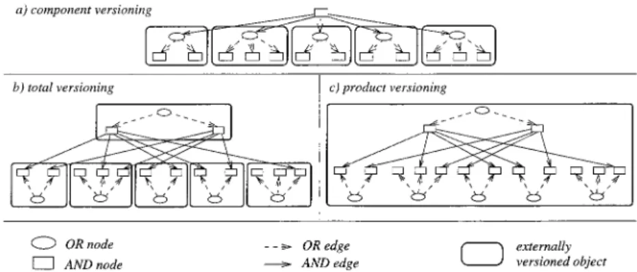
External versioning may be applied in different ways to the composition hier-archy of software objects. Component versioning means that only atomic ob-jects are put under version control. Each object has its own version space, modeled, for example, by a version graph. Total versioning applies to all levels of the composition hierarchy. Product versioning differs from total versioning by arranging versions of all objects in a uniform, global version space.
This classification is illustrated in Figure 9, where externally versioned ob-jects are surrounded by boxes. The AND/OR graph in Figure 9(a) was taken from Figure 7(a), and the graphs shown in (b) and (c) were both copied from Figure 7(b). Note that the topology of an Figure 8. Different kinds of AND/OR graphs and selection orders (II): (a) intertwined; (b) version first.
AND/OR graph shows which objects are versioned, but externally and internally versioned objects are not distinguished. Thus a given AND/OR graph can be accessed in different ways, depending on the version model presented to the user. In particular, in the case of prod-uct versioning the user may select ver-sions of nonroot objects, but this is done in the version space attached to the whole product.
Component Versioning. In compo-nent versioning, the product structure is selected first. Typically, versions of components are organized into version graphs (see, e.g., RCS [Tichy 1985]). A configuration is constructed by assem-bling versions of components; this is called composition model in Feiler [1991a]. Note that the granularity of composition is an “atomic” software ob-ject (rather than fine-grained units such as statements or text lines).
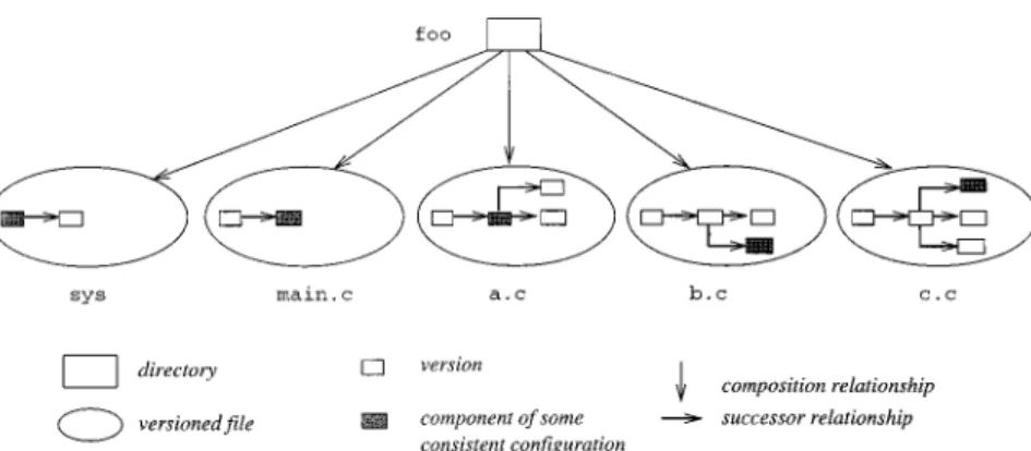
Frequently, the version graphs of dif-ferent components are related only weakly to each other. To illustrate this, Figure 10 shows a sample configuration whose components are located at differ-ent places in the respective version graphs.4 The selection problem can be alleviated by tagging all components of some consistent configuration with the
same symbolic name (or more generally through configuration rules referring to revisions and variants). Thus a configu-ration is represented implicitly through an attribute value rather than as a first-class entity.
Total Versioning. Total versioning generalizes component versioning in that all objects are versioned rather than only the leaves of the composition hierarchy. In contrast to component ver-sioning, versions of composite objects are represented explicitly as entities; atomic and composite objects are ver-sioned uniformly. Whereas component versioning implies that the product structure is selected first, total version-ing may be combined with both the “ver-sion first” and the “intertwined” selec-tion order and can therefore express structural versioning. For example, PCTE [Oquendo et al. 1989] supports extensional versioning of composite ob-jects (“version first”). In contrast, in ClearCase [Leblang 1994] AND/OR se-lections are intertwined: a version of a directory references a set of versioned files (or directories) rather than specific versions of these. A single-version view on the versioned file system is provided through dynamically evaluated configu-ration rules (intensional versioning with dynamic binding).
Product Versioning. Product ver-sioning differs from total verver-sioning by arranging versions of all objects in a
4AND nodes representing versions are placed in-side the OR node representing the versioned com-ponent. Furthermore, the AND/OR graph is aug-mented with successor relationships.
uniform, global version space. It may be regarded as a layer that simplifies se-lection against a versioned object base. Product versioning sets up a transpar-ent single-version view that hides inter-nally maintained versions of objects and relationships from users and tools. Product space and version space are orthogonal to each other: a given model of the product space can be combined with different models of the version space and vice versa. The integration of product space and version space in the
state-based SCM system VOODOO
[Reichenberger 1994] is illustrated in Figure 11, where versioned objects, re-visions, and variants are organized into orthogonal dimensions.
All change-based systems (e.g., the COV system [Gulla et al. 1991], Aide-de-Camp [Software Maintenance and Development Systems 1990], and DaSC [MacKay 1995]) support product ver-sioning to overcome the limitations of component versioning. In general, a change to a software product may affect multiple components. Since the compo-sition model falls short of recording these cross-dependencies, it is difficult to incorporate a change into a product version by selecting the respective com-ponent versions. Therefore in change-based approaches product versions are described in terms of global changes. Note that combination of changes oper-ates at a finer granularity (e.g., text lines) than composition of components.
Product versioning has become more and more popular because of its global view on the software product. A poten-tial problem consists of lacking modu-larity of the version space. All changes, revisions, and variants are global. For example, if there are two implementa-tion variants of a procedure Sort (e.g., QuickSortandHeapSort), we must intro-duce an attribute at the global level in order to enable choices between these variants. An approach to structure the version space (in the COV system) is described in Munch [1996].
4.3 Deltas
To represent versions in the object base, deltas are used both at the coarse-grained and the fine-coarse-grained levels. The selection of an appropriate delta repre-sentation is driven by different require-ments to be considered at the physical and logical level, respectively. Storage and run-time efficiency have to be achieved at the physical level. At the logical level, deltas are used to compare versions in such a way that the user is provided with a high-level description of differences. Furthermore, intensional versioning relies on deltas as well. By processing the deltas, a version is con-structed that must meet the require-ments stated in its intensional descrip-tion. Accordingly, we distinguish between physical and logical deltas. Although many SCM systems use a single delta Figure 10. AND/OR graph augmented with successor relationships.
representation for both purposes [Munch 1993], physical and logical deltas may also be separated (e.g., syntactic merg-ing of program modules stored as text files [Buffenbarger 1995]).
The distinction between directed and symmetric deltas, as illustrated in Fig-ure 2, can be transferred directly to the implementation level. Using directed deltas [Tichy 1982b], a version is con-structed by applying a sequence of changes to some base version. In the case ofembedded deltas,all versions are stored in an overlapping manner so that common fragments are shared. Either each version points to its fragments [Fraser and Myers 1986], or the frag-ments are decorated withcontrol expres-sions for determining the versions in which they are visible (interleaved
del-tas [Rochkind 1975; Leblang and
McLean 1985]).
Please note that the internal delta representation is orthogonal to the ex-ternal version model. For example, in-terleaved deltas may be used to realize both extensional and intensional ver-sioning as well as both state- and change-based versioning. In the follow-ing, the different types of delta repre-sentations are discussed in turn.
RCS [Tichy 1985], which is based on directed deltas, reconstructs versions of text files from the most recent version on the main trunk of the version graph
by applying backward deltas on the main trunk and forward deltas on the branches. RCS deltas are fine-grained, whereas change-based SCM systems such as PIE [Goldstein and Bobrow 1980] and DaSC [MacKay 1995] employ directed deltas at both the coarse-grained and the fine-coarse-grained level. In both systems, the modifications per-formed in a change are stored in a layer. A product version is composed of a se-quence of layers that are stacked on top of each other. (For further details, see the description of PIE in Section 6, in particular, Figure 21.)
Since versions are stored in an over-lapping manner, AND/OR graphs can be classified as embedded deltas. As de-scribed so far, versions can be combined freely to derive bound configurations from some generic configuration. This “combinability” can be constrained by control expressions (configuration rules) stating, for instance, that a certain ver-sion can be selected only when configur-ing a Unixvariant.
Adding control expressions results in an interleaved delta scheme that is real-ized in SCCS [Rochkind 1975] and
DSEE [Leblang and McLean 1985]
among others. Note that both systems implement a version model similar to RCS, which is based on directed deltas. In SCCS and DSEE, fragments of text Figure 11. Product versioning.
lines are tagged with the set of versions in which they are included.
SCCS and DSEE support extensional versioning (of text files) but conditional compilation employs interleaved deltas for intensional versioning. For example, Figure 12(a) illustrates conditional com-pilation in a source file varying with respect to the operating system. Figure 12(b) demonstrates that conditional
compilation can be applied at the
coarse-grained level as well. The figure contains a cutout of a product descrip-tion written in the Proteus Configura-tion Language (PCL [Tryggeseth et al. 1995]). The selected version of the files component depends on the value of the os attribute, which refers to the operat-ing system. In contrast to conditional compilation (single-source versioning), different versions of this component are stored in separate files (version segrega-tion) [Mahler 1994].
Version segregation is vulnerable to
the multiple maintenance problem
[Babich 1986]: a change to a common fragment must be applied to all versions in turn. This is even the case when the fragment is shared at the physical level (e.g., interleaved deltas in SCCS). Merge tools may reduce the multiple maintenance problem by partly auto-mating change propagation. However, single-source versioning is a more ele-gant solution since the change needs to be performed only once for all versions,
although it may still have to be tested in multiple versions.
On the other hand, editing of source files cluttered with control expressions may confuse the user. Multiversion edi-tors overcome this problem by hiding control expressions (see, e.g., P-Edit [Kruskal 1984], MVPE [Sarnak et al. 1988], and COV [Gulla et al. 1991]). A read filter selects a single version, re-moving all control expressions; a write filter constrains the set of versions to which the change is applied. For exam-ple, a general change in common parts of the source file may be performed by setting up a universal write filter and selecting some arbitrary version by the read filter (e.g., the Unix version). If Unix is also selected for writing, the control expressions of all changed parts are set up so that all changes are spe-cific to the Unix version.
4.4 Relations Between Version Model and Data Model
To conclude this section, we discuss the interplay between product space and version space in terms of its implica-tions for database management. When designing a database management sys-tem for software engineering, the de-signer must decide how to support ver-sioning. In particular, there are several alternatives concerning the relations Figure 12. Interleaved deltas: (a) fine-grained level; (b) coarse-grained level.
between the data model and the version model.
Version Model on Top of the Data Model. In this case, version manage-ment is seen as an ordinary database application. Thus the version model is represented by a schema whose under-lying data model is not aware of ver-sioning. This solution has been adopted, for example, by PCTE [Oquendo et al. 1989] and CoMa [Westfechtel 1996], which are based on an EER and a graph data model, respectively. Its main ad-vantage is that the data model is kept simple and potentially application-spe-cific extensions are avoided (a widely accepted uniform version model does not yet exist).
However, implementing version man-agement completely on top of a data-base management system has a number of limitations. For example, there is no support for storing versions efficiently, the transaction manager does not take versioning into account, and so on. Therefore several database manage-ment systems providepredefined classes
for version management (e.g., O2
[GOODSTEP 1995]). In this case, the data model is still not aware of version-ing, but components of the database management system such as storage and transaction manager are modified to support version management effi-ciently.
Version Model Built into the Data Model. If the data model is extended with versioning, applications can be supported through a data-definition
language that provides customized con-structs for defining versioned object types. In addition, the query language is modified so that queries against a versioned database can be written in a convenient and natural way. DAMOKLES [Dittrich et al. 1986], EX-TRA-V [Sciore 1994], and Adele [Estub-lier and Casallas 1994] follow this ap-proach.
If the version model is defined on top of the data model, different types are required for versioned objects and their versions. As argued in Estublier and Casallas [1994] and Sciore [1994], this distinction is awkward and complicates both schemata and queries. Figure 13 illustrates how this problem is solved in Adele. In this example, only one object type is defined for a versioned interface. Adele distinguishes between common attributes shared by all revisions, modi-fiable attributes whose values are revi-sion-specific, and immutable attributes, where each update triggers the creation of a new revision. Furthermore, the at-tribute realization is declared as ver-sioned, meaning that an interface revi-sion may have multiple realization variants.
Data Model on Top of the Version Model. So far, the version model de-pends heavily on the data model, being either defined on top of or built into the data model. In a few SCM systems, such as ICE [Zeller and Snelting 1995] and COV [Munch 1996], the version model is
completely orthogonal to the data
instrumentable version engine that pro-vides a basic delta storage and configu-ration rules by means of which specific version models may be expressed [Con-radi and Westfechtel 1997]. The version engine is not aware of the data model and can thus be combined with any data model (e.g., EER, object-oriented, or simply files).
Both ICE and COV are based on in-terleaved deltas, but use different logics for control expressions. In ICE, version-ing is applied to file-based data. The COV system applies versioning to an EER data model. To this end, a layer that takes care of the consistency con-straints inherent in the data model is placed on top of the version engine (e.g., a relationship is visible only when both ends belong to the currently selected version). Thus this architecture differs considerably from the architecture of conventional database management sys-tems where version model and data model are rather entangled.
5. INTENSIONAL VERSIONING
In Section 3.2 we distinguished between extensional and intensional versioning. Extensional versioning is concerned with the reconstruction of previously created versions and requires version identification, immutability, and effi-cient storage. On the other hand, inten-sional versioning deals with the construc-tion of new versions from property-based descriptions. Intensional versioning is very important for large version spaces, where a software product evolves into many revisions and variants and many changes have to be combined.
In order to support intensional ver-sioning, an SCM system must provide for both combinability—any version has to be constructed on demand—and con-sistency control—a constructed version must meet certain constraints. The con-struction of a version may be viewed as a selection against a versioned object base. The selection is directed by config-uration rules, which constitute an es-sential part of a version model, and is
performed both in the product space and the version space. Having discussed the interplay between product space and version space in Section 4, we are now ready to elaborate on rule-based version construction, a topic that could have been addressed only partially in Section 3.
5.1 Problem: Combinability Versus
Consistency Control and Manageability Configuration rules are used to config-ure consistent versions from a versioned object base. Rules are required to ad-dress the combinability problem. The number of potential versions explodes combinatorially; only a few are actually consistent or relevant. The combinabil-ity problem has to be solved in any version model.
For example, the (state-based) compo-sition model [Feiler 1991a] applies ex-tensional versioning at the component level; that is, previously constructed component versions are reused. Rule-based construction of configurations realizes intensional versioning at the configuration level; that is, new combi-nations of component versions are as-sembled into configurations. Without any constraints, the number of potential configurations is very large. For a prod-uct consisting of m modules existing in v versions, there existvm potential con-figurations (i.e., the number of potential configurations grows polynomially inv). On the one hand, change-based ver-sioning reduces the combinability prob-lem by grouping logically related modi-fications of multiple components. Thus we do not have to worry about which versions of components actually fit to-gether. However, the selection problem has not disappeared. Rather, it has been moved from the product space to the version space [Munch 1996]. In the case of unconstrained combination of changes (each change may either be ap-plied or skipped), there are 2c potential configurations forcchanges; that is, the number of potential configurations grows exponentially in c.
The challenge of intensional version-ing consists of providversion-ing for consistency control while still supporting combin-ability. The space of all potential ver-sions is much larger than the space of consistent ones. The problem of consis-tency control can be addressed both in the version space and in the product space. In the version space, configura-tion rules are used to eliminate incon-sistent combinations; in the product space, the knowledge about software ob-jects, their contents, and their relation-ships is enriched in order to check and ensure product constraints. SCM sys-tems tend to solve the problem in the version space because they frequently only have limited knowledge of the product space (typically, software ob-jects are represented as text files).
Even if a sophisticated tool for con-structing a version is employed, the user must be warned if a new version is created that has never before been con-figured. Although old versions can be assigned levels of “confidentiality” (e.g., tested or released), a new version can-not be trusted blindly. Therefore the configured version is subject to quality assurance (e.g., testing). Potentially, changes to the constructed version need to be performed (correction delta). 5.2 Conceptual Framework for Intensional
Versioning
Figure 14 illustrates our conceptual
framework for intensional versioning. First let us define the central notion of configuration rule: a configuration rule guides or constrains version selection for a certain part of a software product. Thus a configuration rule consists of a product part, which determines its scope in the product space, and a ver-sion part, which performs a selection in the version space (see Section 5.3 for further details).
A versioned object base combines product space and version space and stores all versions of a software product, relying, for example, on interleaved del-tas. The versioned object base is aug-mented with arule baseof stored config-uration rules (e.g., control expressions as shown in Figure 12).
A query consists of a set of submitted configuration rules, each composed of a product part and a version part. A con-figurator is a tool that constructs a ver-sion by evaluating a query against a versioned object base and a rule base. The constructed version has to satisfy bothversion constraints(e.g., consistent selection of the Unix version) and prod-uct constraints(e.g., syntactic or seman-tic consistency). Configurators are dis-cussed further in Sections 5.4 and 5.5.
The configuration process is con-cerned with the binding of generic refer-ences. Often, its result is a bound con-figuration, but it may also deliver a configuration that is partially generic. Figure 14. Intensional versioning.
The latter results in amultistage config-uration process.
Binding can be performed at different points in time. Static binding means that the configurator resolves all un-bound references before any component is accessed. To this end, the configura-tor constructs a table that maps each component name to a specific version. In dynamic binding, each reference is evaluated on demand only (e.g., when a source file is read by a compiler).
Binding may even be deferred until runtime. In this case, a program is con-figured dynamically without stopping its execution. A popular example is Java applets, which are loaded dynamically when they are activated through a Web browser. Dynamic configuration has been studied in the context of distrib-uted systems (see Kramer [1993] for an overview). Up to now, the relations to SCM have not been investigated thor-oughly. Only recently have a few ap-proaches been proposed that apply ver-sion-selection techniques from SCM to
dynamic configuration [Warren and
Sommerville 1995; Schmerl and Marlin 1995]. However, elaborating on this topic goes beyond the scope of this arti-cle.
To sharpen the focus, we also refrain from discussing system building [Bori-son 1989]. Although the conceptual framework illustrated in Figure 14 can be applied to both source and derived objects, the problems to be considered are different in the following respects. —In source version construction, we
have a selection problem in both prod-uct and version space. The selection must be performed so that the out-come of the configuration process obeys all configuration rules and product constraints. Here nondeter-minism may have to be taken into account and the configurator may have to backtrack from wrong selec-tions.
—When constructing derived versions, we primarily have to consider the effi-ciency and accuracy of the build.
Mostly, build rules are deterministic with respect to the result of building. Nondeterminism deals only with the order in which build steps are exe-cuted (the build plan imposes only a partial order on the build steps). Some authors advertise the advan-tages of nondeterministic build rules (e.g., “build some sort program no matter what algorithm and which compiler is used” [Rich and Solomon 1991]). However in many situations it is crucial to control the details of a build without leaving the freedom for nondeterministic choices (e.g., even the functional behavior of a program may depend on whether it is compiled with or without optimization).
Finally, Figure 14 suggests that the rule base is not put under version con-trol. On the other hand, versioning of the rule base is desirable as well
be-cause the configuration rules may
evolve along with the software product. In the case of our sample software prod-uct foo the set of supported operating systems, window systems, and database systems may evolve, as may the con-straints on combining these dimensions of variation. Currently, versioning of the rule base is handled at best in a rudimentary way, such as by storing configuration rules in text files that are subject to version control. As argued in Conradi and Westfechtel [1997], simple time-stamped revisions of the rule base may suffice to reconstruct not only old product versions, but also the configura-tion rules valid at that time. Some fur-ther remarks on this topic follow in Section 7.2.
5.3 Configuration Rules
Intensional versioning is driven by con-figuration rules that are classified in the following. First, built-in rules are hardwired into the respective SCM sys-tem and cannot be changed by the user. For example, a built-in rule may enforce that at most one version of a software object is contained in any constructed
configuration. User-defined rules are supplied by the user (e.g., “select the latest version before May 22nd”).
Version Parts of Configuration Rules. Configuration rules take on different forms depending on how the version space is structured. Figure 15 provides some typical examples that refer to the revision, variant, and change space, re-spectively. Configuration rules are stated as logical formulas, abstracting from the actual syntax as implemented in different SCM systems.
In the revision-space category, config-uration rules refer to the time dimen-sion. Rule (1) selects the latest revision by the maximal time stamp. Rule (2) refers to a revision by its number.
In the variant space, configuration rules refer to values of variant at-tributes. Rule (3) identifies a variant by specifying operating system, window system, and database system. Rule (4) expresses a constraint on the combina-tion of attribute values: the X11 window system is not available under the DOS operating system.
In thechange space,Rule (5) specifies a version in terms of the changes to be applied. Rules (6) and (7) specify further relationships that describe consistent change combinations. Rule (6) states that inclusion of change c2implies that c1 is included as well (c2 is based on c1). Rule (7) states that changes c1,c2, andc3are mutually exclusive (operator
V) (i.e., at most one of these changes may be applied).
space. In Figure 16, a configuration rule is written in the formp:v, wherepand v denote product part and version part, respectively. Rule (1) applies to a single module a (local rule) and selects the version checked out by the current user. The star in Rule (2) indicates global application to all modules so that the same variant is selected throughout the whole product. The product part of Rule (3) denotes all modules reachable from b by a reflective and transitive closure over relationships of type DependsOn; that is, the rule applies to b and to all modules on which b depends transi-tively.
Ordering of Configuration Rules. Configuration rules can be ordered in strictness classes.Aconstraintis a man-datory rule that must be satisfied. Any violation of a constraint indicates an inconsistency. For example, Rule (1) in Figure 17 ensures that all selected ver-sions belong to a given variant. A pref-erenceis an optional rule that is applied only when it can be satisfied. For exam-ple, Rule (2) states that a checked-out version is selected provided it is avail-able. Finally, a default is also an op-tional rule, but is weaker than a prefer-ence: a default rule is applied only when no unique selection could be performed otherwise. For example, Rule (3) selects the most recent version as the default.
Strictness classes determine the order in which configuration rules are evalu-ated (constraints 3 preferences 3 de-faults). In addition, rules may be given priorities. Rules with high priorities are considered before low-priority rules. A priority may be assigned explicitly or Figure 15. Version parts of configuration rules.